Samsung Galaxy Note9 Charging Assembly Replacement Guide
Duration: 45 minutes
Steps: 32 Steps
Hey there, techie! Let’s get that Galaxy Note9 charging assembly swapped out. This guide will walk you through the process, step by step. Feeling nervous? Don’t worry, you got this! And if you need a helping hand, you can always schedule a repair.
Step 1


– Grab your trusty SIM card eject tool and slide it right into the little hole on the SIM card tray.
– Give it a gentle push to pop that SIM card tray out!
Tools Used

Step 2

– Let’s get started by removing the SIM card tray. It’s the first step in getting your device back up and running. If you need help, you can always schedule a repair
Hey there! Don’t sweat it if the SIM card goes on a little adventure and decides to take a dip in the tray. We’ve got your back and know just the peppy dance to make it pop right back into place. So, give it a whirl and say hello to a fully connected device again. If you need help, you can always schedule a repair.
Step 3

– First things first, make sure to power down your phone before we get started on the disassembly adventure!
– Grab a hairdryer, heat gun, or get your hands on an iOpener, and warm up the right edge of your phone’s back for about a minute. This will help loosen up that pesky adhesive lurking underneath!
Tools Used

Step 4


If the adhesive is feeling stubborn, give it a bit more heat and hold off on using brute strength. Too much muscle could shatter that glass.
If your glass is looking like it just survived a rock concert, grab some packing tape and give it a solid wrap. This will create a sturdy surface for your suction cup to stick to, making your repair journey smoother!
– Let’s get that back cover off! First, stick a suction handle to the back cover.
– Now, give that handle a gentle lift to create a little space between the back cover and the phone’s frame. It’s like giving the cover a high five!
– Now, slip an opening pick into that gap – you’re almost there!
Tools Used

Step 5

If the adhesive is being a bit stubborn, just give it some extra heat instead of trying to force it.
– Whoa, look at all that sticky goodness along the top edge and around that camera bezel! Don’t forget, though, there’s less adhesive around the rest of the phone.
– Alrighty, let’s get cutting around the left edge, but be extra careful near that fingerprint sensor, or you might hurt the ribbon cable inside. If you need help, you can always schedule a repair.
Step 6


Keep that pick under control! Don’t poke it in more than halfway when you’re working near the fingerprint sensor or cameras—otherwise, you might just give those internal components a little too much excitement.
– Begin at the center and gracefully glide your opening pick up and down the right side to slice through the adhesive like a pro.
Step 7


Heads up! The corners are a little delicate, so be gentle. Don’t worry, if the adhesive gets stuck, just add a little more heat. You got this!
– Pop an opening pick into the upper-right corner and let it hang out there.
– Grab another opening pick and slide it around to slice through the adhesive at the bottom-right corner.
– Keep that first pick in the phone while you work your magic!
Step 8

– Time to get this repair started. Apply some heat to the left side of the rear panel using a heat gun, hair dryer, or a heated iOpener for about three minutes. This will help loosen the adhesive underneath, making the next steps a breeze. If you need help, you can always schedule a repair
Tools Used
Step 9


Watch out for those corners—it’s where the glass likes to play it weak!
When you’re sliding that opening pick along the left edge near the fingerprint sensor, keep it to halfway or less. You definitely don’t want to snag that delicate ribbon cable hiding inside.
It’s totally okay if those opening picks decide to take a little tumble as the back cover loosens up.
– Hey, let’s get into gear and slide that opening pick into the lower-left corner of the phone’s rear panel. It’s time to make this repair rock! Now, with another pick, let’s follow the left edge, cutting through that adhesive and freeing the rear panel. If you need help, you can always schedule a repair.
Step 10


Feel free to bring out the heavy hitters like an iOpener, a trusty hair dryer, or a heat gun to warm things up while you’re slicing through that adhesive. Let’s keep it cozy as you work your magic!
– Grab your trusty opening pick and gently glide it around the upper-left corner of the rear panel to slice through that adhesive like a pro.
– Now, let’s finish strong! Cut away the last bit of adhesive along the top of the phone. You’re doing great!
Tools Used
Step 11


Hold on tight! Don’t yank that fingerprint sensor ribbon cable out just yet.
The fingerprint sensor cover might just want to hang out with the midframe for a little longer.
– Let’s get this party started! First, we’ll separate the right side of the rear cover.
– Now, tilt the cover up along the left edge. You’ll see the fingerprint sensor ribbon cable. No worries, we’ll get to that next!
Step 12


– Gently slide the spudger’s tip under the fingerprint sensor ribbon cable, and give it a little lift to pop it out of its socket. Easy peasy!
Tools Used

Step 13

– Let’s get started by removing the back cover.
– When you’re ready to put everything back together, follow these steps to re-install the back cover:
– Use tweezers to gently peel away any remaining adhesive from the phone’s chassis. Then, give the adhesion areas a good cleaning with some high-concentration isopropyl alcohol (at least 90%) and a lint-free cloth. This will help prep the surface for the new adhesive. Don’t worry too much about getting every last bit of adhesive off – just focus on removing any larger pieces.
– Before you apply the new adhesive and seal everything up, turn on your phone and test it out to make sure your repair was a success.
– Now it’s time to apply the new adhesive to the back cover. Line up one edge of the glass against the phone chassis and firmly press it into place. If you need help or feel unsure about any part of the process, you can always schedule a repair with Salvation Repair.
Tools Used

Step 14


– Let’s get started by removing the nine 4mm screws that hold the upper midframe in place – grab your trusty Phillips screwdriver and get to work. If you need help, you can always schedule a repair


Step 16


The adhesive might be feeling a bit tired, but no worries! Grab an opening pick and gently slice through it if you need to.
– Let’s peel that wireless charging coil right off the battery, starting from the left side. No worries, it’s like taking off a sticker!
– Now, for reassembly, we’re going to snap the midframe into place first, before sticking that wireless charging coil back on. Piece of cake!
Step 17


– Gently use the tip of a spudger to unplug the cheerful orange ribbon cable that’s connecting the battery to the motherboard. You’ve got this!
Tools Used
Step 18

– Let’s get started! First up, take out those nine 4 mm Phillips screws from the plastic cover sitting next to the battery. You’ve got this!

Step 20


The lower midframe is easy to remove and replace – it simply snaps into and out of place.
– Let’s get that lower midframe out! Stick the tip of your spudger in the top of it.
– Now, gently pry the lower midframe away from the phone. Be careful not to damage anything!
– Success! You’ve removed the lower midframe. Feeling good about this?
Tools Used
Step 21


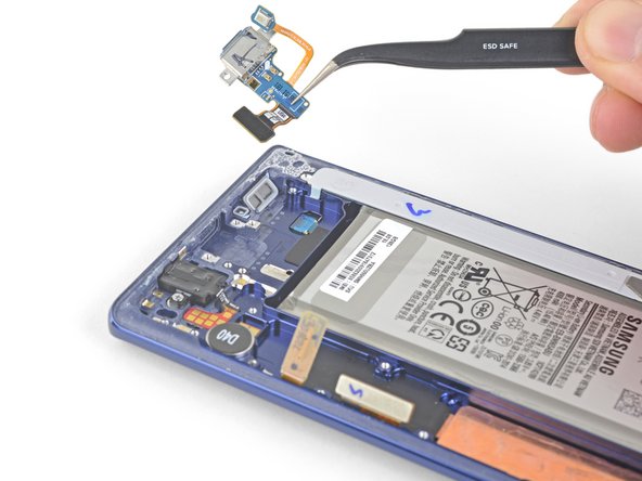
– Time to get that front camera out – use the tip of a spudger to carefully pry the connector straight up and out of its socket. Take your time, it’s easier than you think!
– Now, grab those tweezers and gently remove the front camera. If you need help, you can always schedule a repair
Step 22


– Time to get started – use the tip of a spudger to carefully disconnect the iris scanner from the motherboard. Take your time, it’s easier than you think!
– Next, grab your trusty tweezers and gently remove the iris scanner. If you need help, you can always schedule a repair


Step 24


– Grab your trusty spudger and gently pry away the display cable from the motherboard. It’s a simple move, so you got this!
Tools Used
Step 25


– Now it’s time to disconnect the touchscreen cable from the motherboard. Use the flat end of a spudger to gently pry it loose – you got this! If you need help, you can always schedule a repair
Tools Used
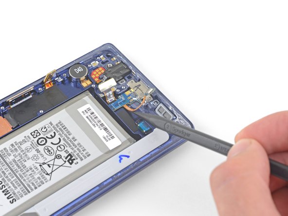
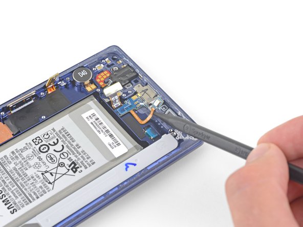
Step 26


– Now it’s time to carefully disconnect the charging assembly from the motherboard – simply use the flat end of a spudger to get the job done. If you need help, you can always schedule a repair
Tools Used
Step 27


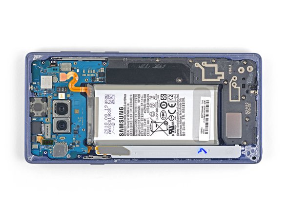
– Let’s get started by removing the three 4mm Phillips screws that hold the motherboard in place.
– Take a look for the triangles next to the holes – they’ll give you a hint about where the screws go. If you need help, you can always schedule a repair
Step 28


Gently move those ribbon cables out of the way as needed. If the motherboard gets caught on any cables, don’t pull it – you might damage something. Take your time and work carefully to avoid any snags. If you need help, you can always schedule a repair
– Time to get this motherboard out – use a spudger to carefully pry it loose from the upper-left corner.
– Now, gently lift the motherboard out. If you need help, you can always schedule a repair
Tools Used
Step 29
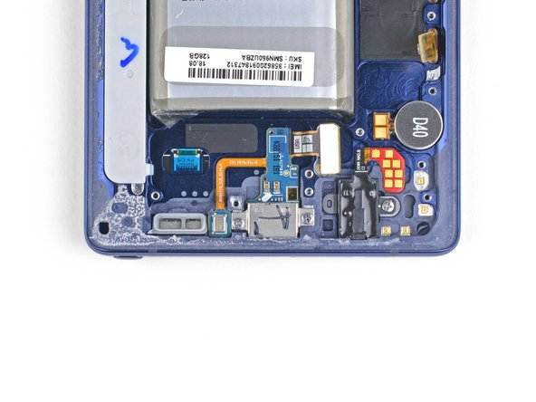

– Go ahead and unscrew those two 3.2 mm Phillips screws from the charging assembly. You’ve got this!

Step 31
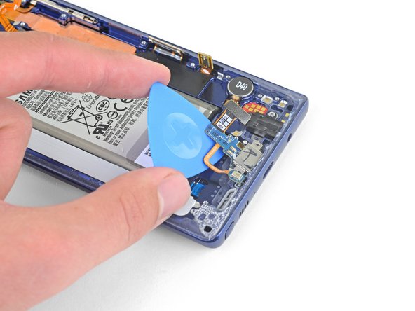

– Now it’s time to get that charging assembly out – use an opening pick to carefully slide underneath and gently pry it away from the phone. If you need help, you can always schedule a repair