How To Replace Samsung Galaxy A15 Rear Cameras Guide
Duration: 45 minutes
Steps: 30 Steps
Ready to give your Samsung Galaxy A15 a little camera makeover? This guide will help you swap out the rear cameras with ease! Whether you’re just changing one or going all out on the primary, ultrawide, and macro modules, you can tackle this project like a pro. Just breeze past the steps for any cameras you’re not updating. And when you’re putting everything back together, don’t forget to snag some replacement adhesive for that back cover. If you need help, you can always schedule a repair.
Step 1


– First things first, unplug all those cables and give your phone a nice little power nap by turning it completely off.
– Now, let’s bring up the shutdown menu! Press and hold the power button and the volume down button together like a pro!
Step 2

A hair dryer can come in handy, but watch out for overheating your phone—the display, internal battery, and plastic back are all a bit sensitive to heat. Aim for a temperature that’s just warm enough to make you think, ‘Hmm, that’s a cozy vibe!’
– Warm up that iOpener and let it chill on the right edge of the back cover for a solid two minutes. You’ve got this!
Tools Used


Step 3

Heads up! There’s an extra layer of adhesive hanging out near the bottom of the phone. Other than that spot, keep your digging no deeper than 4 mm from the edge. Happy repairing!
– While the adhesive takes its sweet time to soften, here’s some handy info for you:
– The back cover is held in place by adhesive along the edge of the frame.
Step 4


If you’re running into a bit of a sticky situation, just crank up the heat a little more to melt that adhesive. You’ve got this!
– Grab a suction handle and stick it on the back cover, aiming for the center of the right edge like a pro.
– Give that suction handle a good pull with some solid, steady strength to open up a little gap between the cover and the frame.
– Slide an opening pick into that gap you just created and get ready to work your magic!
Tools Used

Step 5


– Gently glide your opening pick along the right edge, slipping it between the back cover and the frame to cut through that sticky adhesive.
– Pop your opening pick into the bottom right corner to prevent the adhesive from sealing up again.
Step 6

– Warm up your iOpener and place it on the bottom of the back cover for two minutes. You’ve got this!
Tools Used
Step 7


– Slide another opening pick into the bottom right corner and gently glide it along the bottom edge to cut through that pesky adhesive.
– Keep your opening pick snug in the bottom left edge to stop the adhesive from sealing back up.
Step 8

– Warm up your iOpener and place it on the left side of the back cover for a cozy two minutes.
Tools Used
Step 9


Keep your pick to a maximum of 4 mm deep – we want to keep those rear cameras and flash safe and sound!
– Pop in another opening pick at the bottom left corner and glide it along the left edge to cut through that sticky adhesive like a pro.
– Keep your opening pick snug in the top left corner to stop that adhesive from trying to seal up again.
Step 10

– Give your iOpener a little warm-up and then place it on the top of the back cover for two minutes. You’ve got this!
Tools Used
Step 11


– Pop in another opening pick at the top left corner, keeping it at the same depth, and glide it along the top edge to neatly slice through that pesky adhesive.
– Keep your opening pick snug in the top right corner to stop the adhesive from making a comeback.
Step 12


Be sure to gently insert your pick no more than 4 mm to keep those rear cameras and flash safe and sound!
– Gently slide your opening pick along the top edge of your phone and give it a little twist to pop those camera clips free.
– Now, just glide your pick around the edges of the camera modules to release the rest of those clips. Easy peasy!
Step 13


– Once you feel the adhesive loosening up around the edges, gently slide your opening pick deeper into the bottom edge, starting from the bottom left corner.
– Now, glide your pick along the bottom edge, slicing through the remaining adhesive like a pro!
Step 14


Now’s the perfect moment to power up your phone and give all the functions a quick test before sealing it up tight. Just remember to turn your phone off completely before diving back into the repair work!
– Gently lift off the back cover and set it aside.
– As you put everything back together:
– Use tweezers or your fingers to clear away any stubborn adhesive bits. If it’s being a bit tricky, a little heat and some isopropyl alcohol (90% or higher) can work wonders to loosen it up.
– For those using custom-cut adhesives, be sure to check out this guide.
– If double-sided tape is your go-to, follow this guide for the best results.
Step 15

– Time to get down to business! Carefully take out the fifteen 4 mm-long screws that are holding the frame to the chassis. You’ve got this!
Step 16


– Grab your trusty spudger and gently lift up to disconnect the fingerprint button press connector from the motherboard. You’ve got this!
Tools Used

Step 17


– Gently slide your opening pick right above the SIM card tray cutout to create a little gap between the frame and your phone. You’ve got this!
– Now, glide that pick down the left edge of the device to pop those frame clips loose. Easy peasy!
Step 18


If your opening pick decides to take a little vacation from the phone, just pop it back in at the last corner that was feeling a bit loose.
– Keep gliding your opening pick around the edge of the phone until every last clip pops open. You’ve got this!
Step 19


– Gently lift the frame straight off the phone, like you’re peeling a banana—smooth and steady!
Step 20


– Grab that spudger and use its flat end to gently lift up and disconnect the battery press connector from the motherboard. You’ve got this!
Tools Used
Step 21


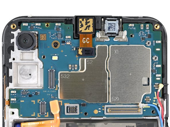
The connector marked ‘OCTA’ isn’t hanging out with the board—it’s actually having a little party with the display cable connector. Be sure to give them a gentle separation and disconnect them from each other.
– Gently slide the flat end of a spudger under the little lip of the top ‘OCTA’ cable connector.
– Carefully lift the top connector away from the bottom one until they part ways.
Tools Used


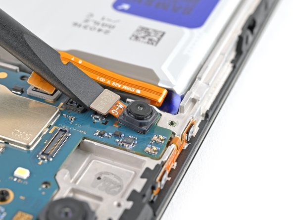
Step 23


– Gently use the flat end of a spudger to lift the ‘MAIN’ connector off the motherboard and disconnect it. You’ve got this!
Tools Used
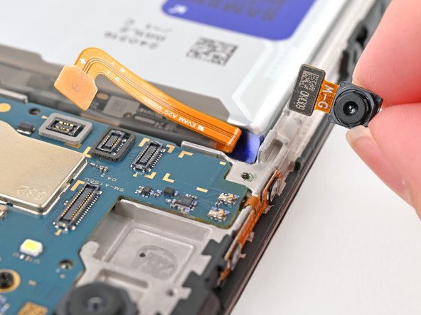
Step 24


– Grab that interconnect cable and gently detach it from the phone. You’re doing great!


Step 27

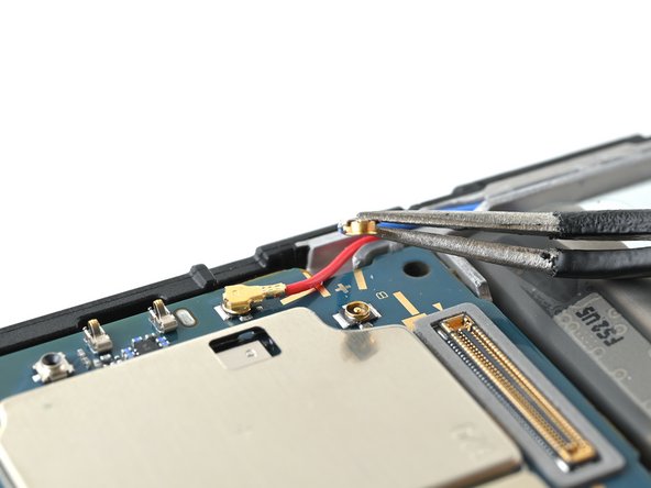
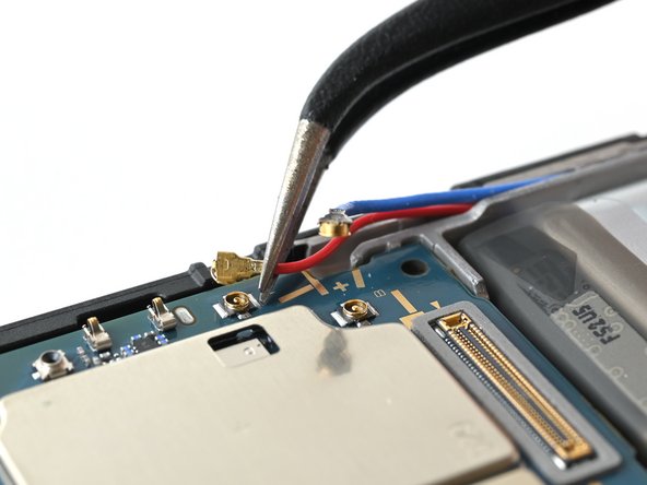
– Gently slide one arm of those nifty angled tweezers under the metal neck of each antenna coaxial connector on the motherboard and lift it straight up to disconnect—easy peasy!
– When it’s time to put everything back together, grab those tweezers again to keep the connector steady over its socket. Then, with a little help from your finger or a spudger, press down gently—the connector should click right into place. If it’s being a bit stubborn, just adjust the head and give it another go!
Tools Used

Step 28

– Grab your trusty Philips screwdriver and unscrew that 3 mm-long screw holding the motherboard snugly in place. You’ve got this!
Step 29


– Gently take hold of the motherboard by its corners and lift it up and out of the phone with care.


