How to Replace Nintendo Switch Family Bluetooth Antenna Guide
Duration: 45 minutes
Steps: 74 Steps
Hey there! Ready to become a repair hero? Time to dive in and save the day with your trusty tools. Let’s bring that device back to life together. Remember, if you need assistance, you can always schedule a repair with our expert team. Let’s do this!
Step 1


Hey there! Before diving into this repair adventure, make sure your device is fully shut down. If you need help, you can always schedule a repair.
– Give that little round button on the back of your Joy Con a good press and hold, like you’re starting a secret mission.
– While you’re holding it down, give the controller a gentle upward slide to release it. Easy peasy!
Step 2


Don’t forget to repeat the same breezy process for the other Joy Con!
– Slide that Joy Con all the way up until it pops off the console. You’re doing great! If you need help, you can always schedule a repair.
Step 3

As you embark on this repair journey, remember to keep track of each screw and make sure it finds its way back to its original home. If you need help, you can always schedule a repair.
– Grab a Y00 screwdriver and take out those four 6.3 mm-long screws holding the rear panel in place. Screwdriver in hand, you’re one step closer to success!
Step 4


To avoid those pesky screws giving you a hard time, gently apply downward pressure, take it easy, and consider switching to a different JIS 000 or PH 000 driver if the screws are being stubborn.
– Get ready to dazzle by using a JIS 000 driver or an official iFixit PH 000 driver to bid adieu to the screws holding tight the rear panel:
– Say cheerio to a single 2.5 mm-long screw residing at the top border of your device
– Wave goodbye to two 2.5 mm-long screws chilling at the base of your device
Step 5


– Grab your trusty JIS 000 screwdriver or the official iFixit PH 000 driver and let’s get tinkering! We’ve got two 3.8 mm screws standing guard on each side of your device. Let’s show them who’s boss. If any part of this feels like a puzzle, no worries—just schedule a repair, and we’ve got your back!
Step 6


Before we rock on to the next step, let’s pop that microSD card out of its cozy little slot.
– Give a little friendly tap to the kickstand on the back of the device to make it flip up, just like saying hello to an old friend.
Step 7

– Grab your trusty JIS 000 screwdriver or the official iFixit PH 000 driver and pop out that 1.6 mm screw hiding in the kickstand zone. You’ve got this!
– Now, just close up that kickstand. Nice and easy!
Step 8


The game card cartridge flap is like a little gatekeeper that connects to the other half of the plastic shell. If it’s closed, it makes it tricky to fully lift up the rear panel. Just a friendly heads-up while you navigate through the repair process!
– Pop open the game card cartridge flap like it’s a surprise party waiting to happen!
– Gently lift the rear panel from the bottom of the device and give it a little wiggle to remove it. You’re doing great!
Step 9

– Grab your trusty JIS 000 screwdriver or the sleek iFixit PH 000 driver and twist out the 3.1 mm screw holding down the microSD card reader. Easy peasy! If you need help, you can always schedule a repair.
Step 10


– Grab your fingers or a trusty set of tweezers, and carefully lift the microSD card reader straight up from the device to disconnect and remove it. Easy does it!
– When you’re putting everything back together, make sure the press connector beneath the foam pad is snugly attached to the motherboard. You might find it easier to remove the foam pad before popping the card reader back in. And remember, if you need help, you can always schedule a repair.
Tools Used

Step 11

– Grab your trusty JIS 000 screwdriver or the nifty iFixit PH 000 driver and get to work on those six 3 mm screws holding the shield plate in place. It’s like a mini workout for your fingers! If those screws give you any trouble, remember, you can always schedule a repair.
Step 12


Hey, if the foam is being a bit stubborn and not peeling off smoothly, don’t sweat it! Avoid forcing it as it might rip. Try gently peeling from different angles to ease it off. If you need help, you can always schedule a repair.
– Gently lift the foam strip at the top edge of your device, right by the fan exhaust port, using your fingers or some tweezers. You’ve got this!
Tools Used
Step 13


To keep things cool and running smoothly, there’s a fun pink thermal compound connecting the shield plate to the copper heat sink. This nifty setup helps the Switch stay chill, avoiding any overheating meltdowns.
Don’t be surprised if you encounter a little resistance – it’s totally normal. The shield plate and heat sink have a cute bond with some thermal paste, like best pals sticking together.
– Gently slide a spudger under the shield plate along the edge of your device.
– Carefully pry it upwards to lift off the shield plate and set it aside.
– You can totally reuse that pink thermal compound—just handle it with care! Keep it clean and ensure it snugly connects the heat sink to the shield when you put everything back together.
– If a new compound is needed, check out our thermal paste guide to safely swap out the old stuff for a fresh one like K5 Pro when reassembling.
Tools Used


Step 14


– Grab your trusty spudger and gently lift that battery connector straight up and out from its cozy little socket on the motherboard. Easy does it! Need some backup? Feel free to schedule a repair.
Tools Used
Step 15

– Grab your trusty JIS 000 screwdriver or the slick iFixit PH 000 driver, and let’s get to it. Remove those three 3 mm screws holding the heat sink to the motherboard. If you need help, you can always schedule a repair.
Step 16
The foam is super fragile and can rip easily. Here’s a slick technique to help you peel it off like a pro:
Just peel back the foam enough to give the fan some breathing room.
– Gently lift off those two foam pieces that are cozied up to the heatsink and fan. They just need a little encouragement!
– Slide the tip of your trusty spudger under the part of the foam that’s playing hard to get.
– Use your finger to give the top of the foam a little press, keeping it steady while you work your magic.
– Now, roll that spudger tip all the way to the other end of the foam to set it free. You’re doing great!
Tools Used
Step 17


A little bit of resistance is totally normal here! That’s just the heat sink giving a friendly hug to the CPU thanks to some thermal paste. No worries, you got this!
– Grab your trusty spudger or just your fingers and gently lift that heatsink off the motherboard. It’s time for a little separation!
– Say goodbye to the old thermal paste! Use some high-concentration (90% or higher) isopropyl alcohol and a microfiber cloth to give the heat sink and CPU a good clean. Don’t forget to apply some fresh thermal paste to the CPU before putting everything back together.
– Make sure to coat all the surfaces that previously had thermal paste. This includes the spot between the heatpipe and aluminum shield, the Switch’s secret weapon for extra cooling.
Tools Used

Step 18


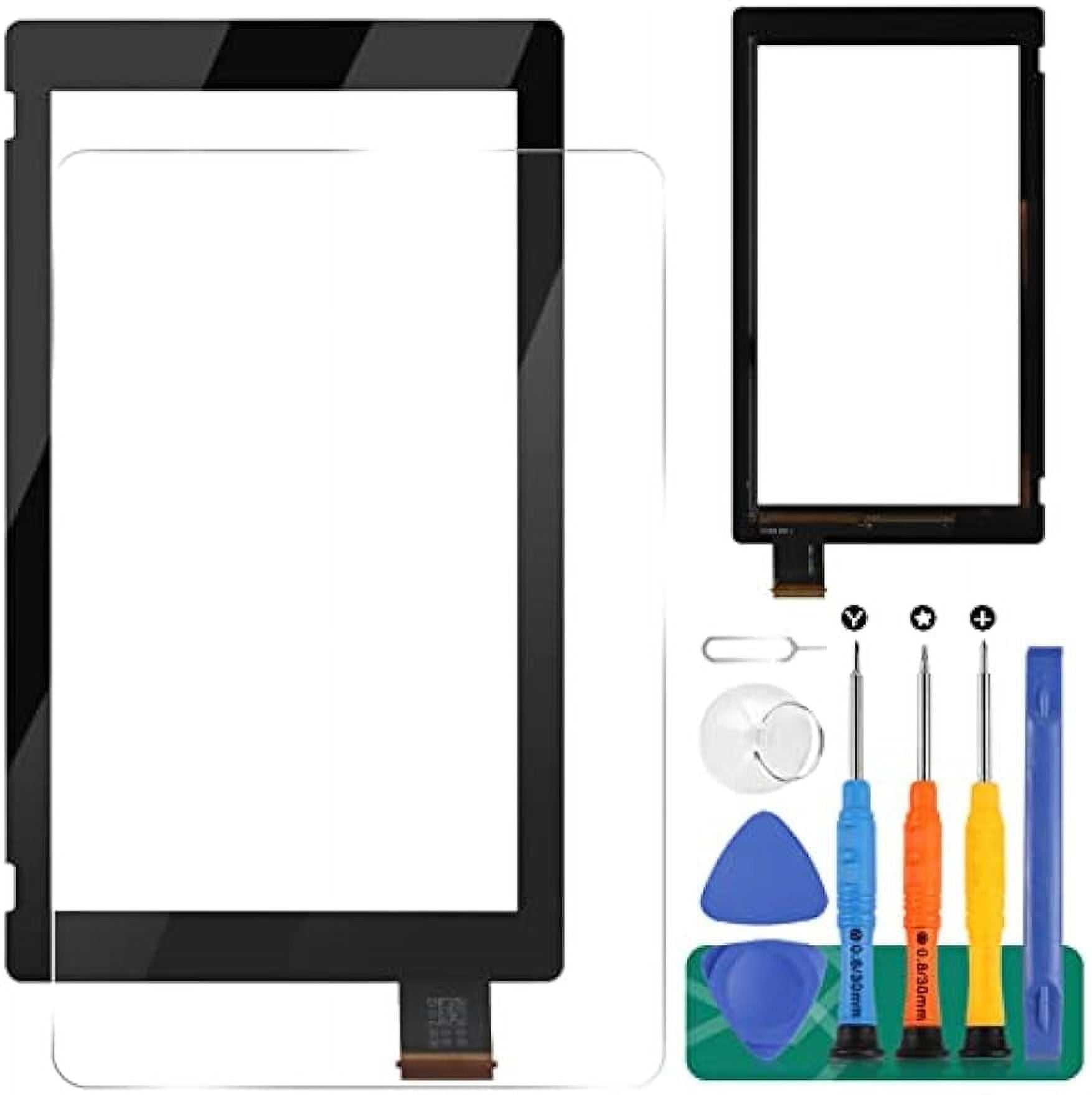
– Grab an opening tool or your fingernail and gently pop up the tiny, hinged flap on the ZIF connector for the digitizer cable. If you need help, you can always schedule a repair.
Step 19


Gently coax the cable into the connector. If it’s being stubborn, make sure the little flap is lifted, adjust the cable, and give it another go.
If your touchscreen is playing hard to get after the repair but your Game Card reader is still in the game, double-check that the cable is snugly in place. And if your Game Card reader is also on strike, take a peek at the Game Card connector in the next step instead.
– Grab those trusty tweezers and smoothly slide the digitizer cable out of its connector on the game card reader board. It’s a horizontal move, folks!
– When you’re putting it all back together, remember to have that ZIF connector’s locking flap in the upright position.
– With the cable running parallel to the board, gently guide it into its connector. If you hit a snag, don’t sweat it—just schedule a repair.
Tools Used
Step 20


If your touch screen is playing hard to get or those game cards are being shy after putting everything back together, it’s possible that this pesky press connector isn’t fully snug. Go ahead and give it a gentle disconnect, then reconnect it and see if that does the trick!
– Grab your trusty spudger and pop the headphone jack and game card reader connector straight up to detach it from the motherboard. Easy does it!
– When you’re ready to reconnect those little guys, just line them up nice and even, and press down on one side till you hear that satisfying click. Then do the same on the other side. Avoid pressing the middle; you don’t want any bent pins ruining your day. If things go awry, schedule a repair for backup!
Tools Used
Step 21

– Grab your trusty JIS 000 screwdriver or the official iFixit PH 000 driver and let’s get to work! Carefully unscrew the three 3.1 mm screws that are holding the headphone jack and game card reader board snugly in place. You’ve got this!
Step 22


– Gently wiggle out the headphone jack bracket using a pair of tweezers or your fingers.
Tools Used
Step 23


– Grab a pair of tweezers or use your fingers to gently remove the headphone jack and game card reader board.
Tools Used
Step 24


– Grab your trusty opening tool, spudger, or even your fingernail and gently lift the small, hinged locking flap on the LCD ribbon cable ZIF connector. You’ve got this!
Tools Used
Step 25


– Grab a trusty pair of tweezers and gently pull that ribbon cable straight out of its cozy connector on the motherboard. You’ve got this!
Tools Used
Step 26


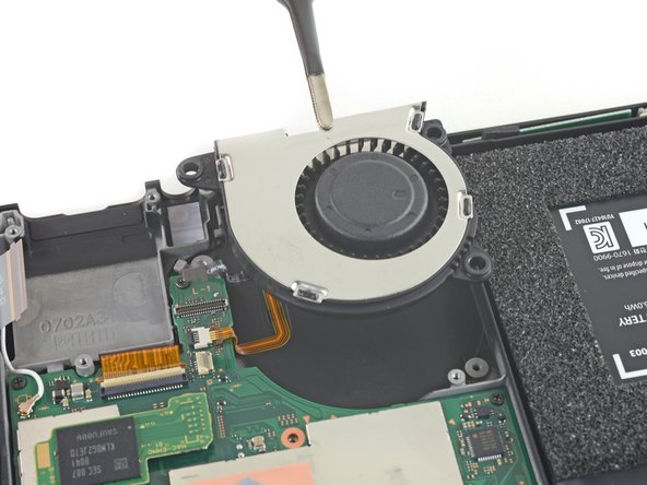
– To make things easier, gently lift the little, swingy locking flap on the ZIF connector of the fan cable using an opening tool, spudger, or even your trusty fingernail.
Tools Used
Step 27


– Gently grab your trusty tweezers and carefully unplug the fan cable from its motherboard connector. If you need help, you can always schedule a repair.
Tools Used
Step 28


– Grab a trusty opening tool—be it a spudger or just your capable fingernail—and gently pop up that tiny, hinged flap on the ZIF connector for the power and volume button ribbon cable. If things get tricky, you can always schedule a repair.
Tools Used
Step 29


– Grab a trusty pair of tweezers and gently tug that ribbon cable straight out of its cozy connector on the motherboard. You’ve got this!
Tools Used
Step 30


– Grab your favorite opening tool or even your trusty fingernail, and gently pop up that little, hinged locking flap on the smaller LCD ribbon cable ZIF connector. It’s easy-peasy! And hey, if you find yourself in a pickle, remember you can always schedule a repair.
Tools Used
Step 31


– Grab a trusty pair of tweezers and gently wiggle that ribbon cable free from its snug home on the motherboard. You’ve got this!
Tools Used
Step 32


– Grab your trusty spudger, your fingernail, or an opening tool and gently pop up that tiny, hinged lock on the Joy Con sensor rail’s data cable ZIF connector. Remember, if you need help, you can always schedule a repair.
Tools Used
Step 33


– Grab a trusty pair of tweezers and gently pull that ribbon cable straight out of its cozy connector on the motherboard. You’ve got this!
Tools Used
Step 34


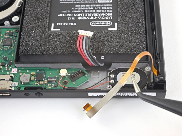
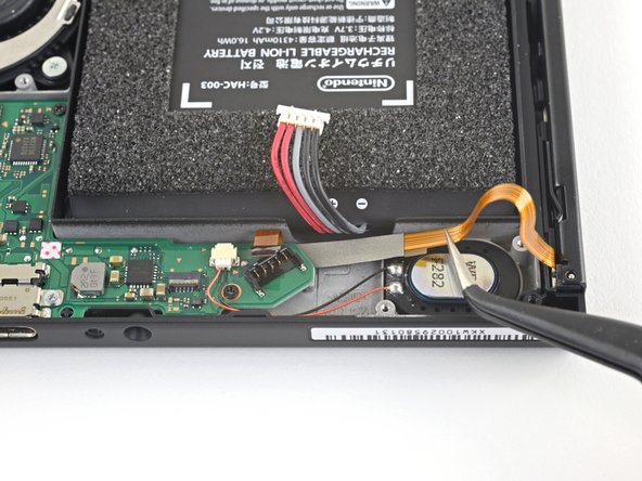
– Get ready to rock and roll by using the point of a spudger to lift the black antenna cable straight up and out of its socket on the motherboard.
Tools Used
Step 35


– Gently lift the white antenna cable straight up out of its socket on the motherboard using the tip of a spudger. You’re doing great!
Tools Used
Step 36


Avoid tugging on the connector using the speaker wires. They’re paper-thin and can break off in no time!
– Gently grab the right speaker connector with your fingers or a trusty pair of tweezers and pull it straight out from its cozy spot on the motherboard. You’ve got this!
Tools Used
Step 37


Hey there! Be super gentle when handling the connector—give those speaker wires a break! They’re delicate little things and can snap off the connector if you tug too hard.
– With the grace of a ninja, use your fingers or a trusty pair of tweezers to gently slide the left speaker connector straight out from its socket on the motherboard. If you need help, you can always schedule a repair.
Tools Used
Step 38


– Grab your trusty spudger, an opening tool, or even just your fingernail to gently lift the tiny flip-flap on the Joy Con sensor rail’s data cable ZIF connector. If you need help, you can always schedule a repair.
Tools Used
Step 39


– Grab those trusty tweezers and gently slide the Joy Con rail data cable straight out of its connector on the motherboard. If you need help, you can always schedule a repair.
Tools Used
Step 40

– Grab your JIS 000 screwdriver or the trusty iFixit PH 000 driver, and let’s get down to business with these screws:
– Four screws, each 2.5 mm long
– Two screws, each 3.1 mm long
Step 41


– Slide a spudger into the space between the motherboard and the frame like a pro.
– Gently lift the motherboard up and out from the frame, as if you’re giving it a little hug goodbye.
Tools Used
Step 42

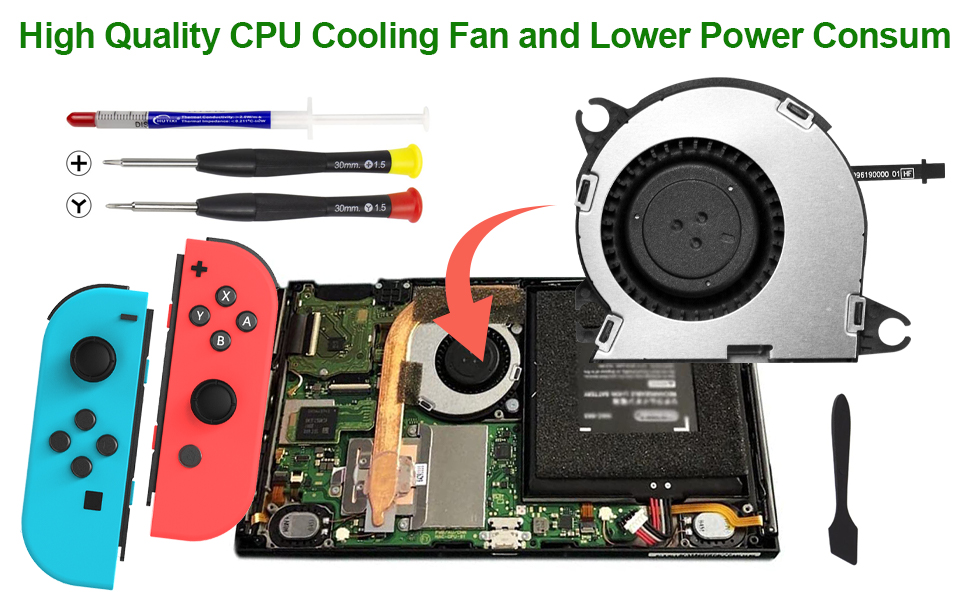
– Grab a hold of your JIS 000 screwdriver or official iFixit PH 000 driver, and let’s tackle those three 4.8 mm screws standing between us and the fan!
Step 43

Check out the new replacement part and compare it to the original. You might have to move some extra bits and bobs like rubber thingamajigs over to the new part before popping it in.
– Grab a trusty pair of tweezers or just use your fingers to gently lift the fan straight up and out of the device. You’ve got this!
Tools Used
Step 44

These screws are really cranked down tight, making them a bit of a challenge to remove. To avoid stripping them, give a solid push downwards, take your time, and if they’re stubborn, try switching to a different screwdriver. You’ve got this!
– Grab your trusty JIS 000 screwdriver or the official iFixit PH 000 driver and let’s get to work! Carefully unscrew those four 3.7 mm screws that are keeping the right Joy Con rail snug against the device’s frame. You’ve got this!
Step 45


Be careful not to catch the rail’s data cable on the device frame while you’re taking it off. We want smooth sailing here!
– Time to give that right Joy Con sensor rail the boot!


Step 48

These screws can be pretty stubborn, so don’t get discouraged! Give them a solid push down while working slowly, and if they’re being particularly tricky, try switching up your screwdriver. You’ve got this! And remember, if you need help, you can always schedule a repair.
– Grab a JIS 000 screwdriver or a trusty iFixit PH 000 driver, and let’s make some magic happen! Carefully remove the four 3.7 mm screws that are holding the left Joy Con rail snug against the device’s frame. You’re doing great!
Step 49


– Gently detach the left Joy Con sensor rail from the device. You’ve got this!
Step 50

– Get ready to rock and roll by using the flat end of a spudger to gently lift up the taped down power/volume ribbon cable.
Tools Used


Step 53

– Gently coax the power and volume buttons out using a pair of blunt nose tweezers. You’ve got this!
Tools Used


Step 55


– Keep tracing that wire and gently guide it along the way!


Step 58

If you’re feeling crafty, a hair dryer, heat gun, or hot plate can do the trick, just remember not to get things too toasty. We don’t want a crispy display or a hot mess with the battery. Stay cool while heating up!
– Warm up your iOpener and gently place it on the bottom edge of the screen for about two minutes to loosen up that sticky adhesive.
Tools Used

Step 59


If things are getting tricky, don’t sweat it! Just give it another go with a little extra heat if needed.
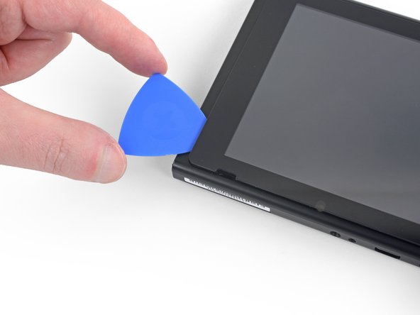
– Stick a suction cup on the bottom-left of the screen, like it’s about to become best buddies.
– Give that suction cup a good, solid pull—put some muscle into it—to form a nifty gap.
– Slide the pointy end of an opening pick into the gap, but don’t go overboard—just about 5 mm is perfect.
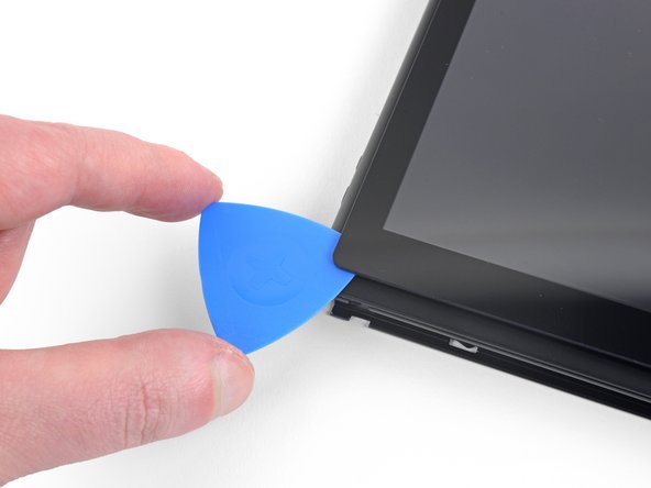
Step 60


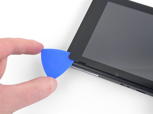
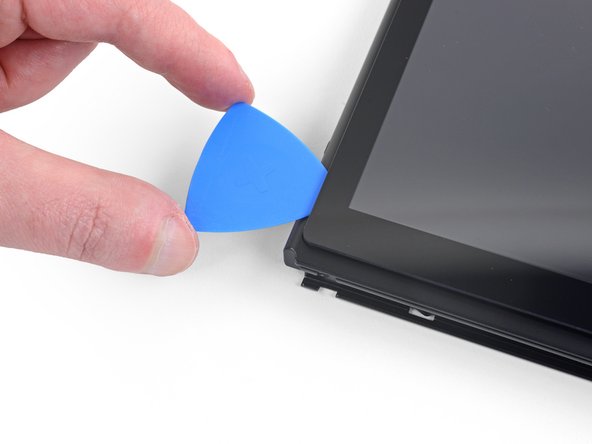
– Gently slide the opening pick along the bottom edge of the screen to smoothly slice through the adhesive.
– Keep the pick inserted in place to make sure the adhesive doesn’t stick back to the frame.
Step 61


– Time to get your groove on, insert another opening pick to party to the left of the first pick.
– Slide that opening pick back to the cool left side of the device.
– Let that opening pick hang out in there, it’s all good.
Step 62

– Warm up the left side of the screen for about two minutes to help ease the sticky stuff holding it down. If you need help, you can always schedule a repair
Step 63

– Keep on sliding that opening pick around the bottom-left corner to cut through the adhesive like a pro!
Step 64


– Keep on smoothly gliding the opening pick down the left side of the screen to effortlessly cut through the adhesive.
Step 65

– Warm up the top edge of the screen for about two minutes to give the adhesive a little nudge.
Step 66

– Keep gliding that opening pick around the top-left corner of the screen to cut through the adhesive like a pro!
Step 67


– Keep sliding that trusty opening pick along the top edge of the screen to gently cut through the adhesive. You’ve got this!
Step 68

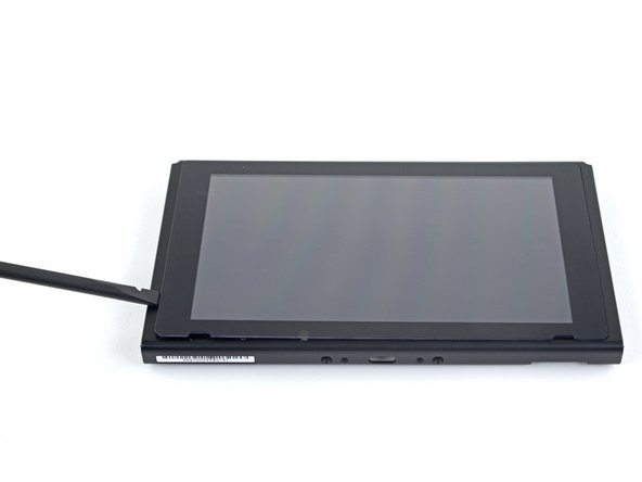
– Warm up the right edge of your screen for about two minutes to loosen that sticky adhesive grip.
– Gently slide the flat end of a spudger into the little gap along the left edge of the screen.
– With care and a steady hand, lift the left edge of the screen, opening it up like a charming book.
Tools Used
Step 69


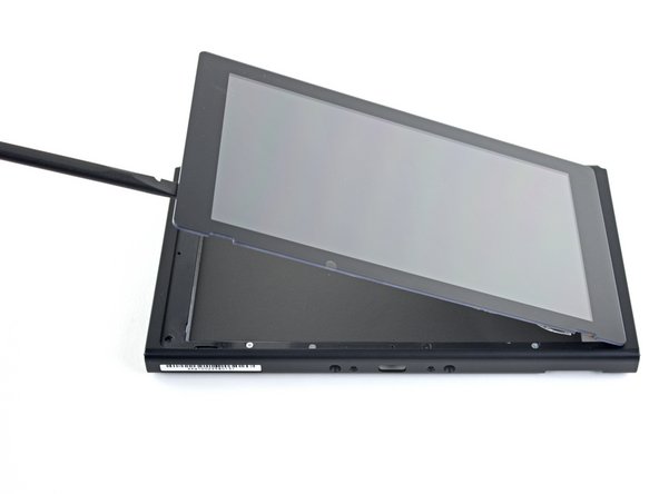
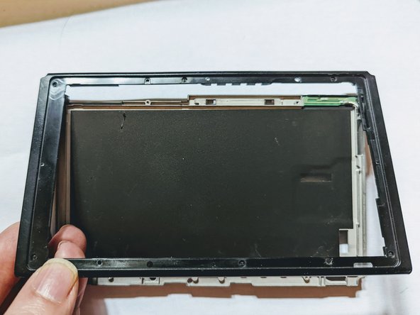
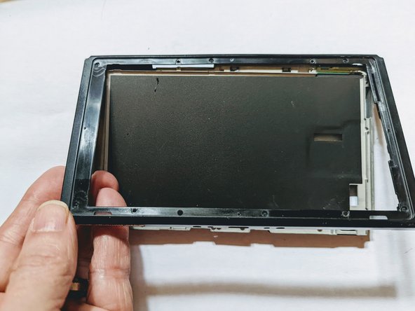
Be careful not to catch any of those ribbon cables on the frame while you’re taking off the screen. They can be a bit tricky, but you’ve got this!
– Gently lift up the right side of the screen, making sure to guide the ribbon cables out smoothly. Don’t worry, it’s like the screen is doing a little dance! If the adhesive on the screen is still sticky, you’re in luck – use it again. If not, no need to fret! Just grab some Tesa tape or any double-sided tape and give the screen a new sticky hug.


Step 72

– Make sure the coax wire is clear of any pesky obstructions and isn’t tangled up inside the device. Keep it breezy!
Step 73


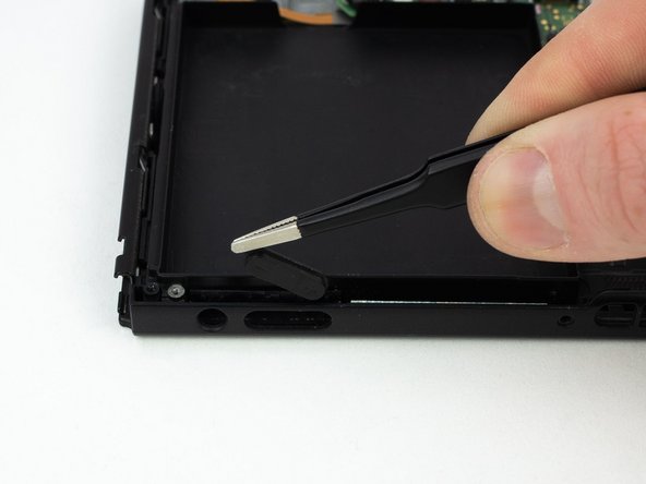
– To free the antenna, gently grasp it and pull upwards to release it from its light adhesive seal.
Step 74

Hey there! Just a heads up – when you get a new antenna, it might not include the black plastic support piece. No worries, though! You can simply transfer it from the old one to the new antenna. If you need any assistance, feel free to schedule a repair with us for help!
– Gently guide the coax cable through the opening in the frame. Keep it smooth and steady, and you’ll be all set!