How to Replace Samsung Galaxy S21 Ultra Screen: Step-by-Step Tutorial
Duration: 45 minutes
Steps: 38 Steps
Galaxy S21 Ultra (SM-G998B/DS)
Keep that battery under 25% before diving in!
Friendly Reminder:
Ready to tackle that cracked screen on your Samsung Galaxy S21 Ultra? You’ve come to the right place! This guide is tailored for the SM-G998B/DS (international) model, but keep in mind that other models might have an extra antenna cable hanging out in the midframe. If your frame is looking a bit bent out of shape, it’s a good idea to swap it out to ensure your new screen fits snugly and avoids any pesky pressure damage. And hey, if your battery is puffing up like a balloon, make sure to handle it with care! Before diving in, let’s get that battery below 25% to minimize the risk of any thermal surprises during the repair. Just a heads up: this guide focuses on swapping out the screen while keeping the original frame and motherboard intact. However, if you’ve got a replacement screen that comes with a new frame (or chassis), you’ll be in for a different adventure. Double-check you have the right part before you start! While it’s not a must to remove the interconnect cables for the screen replacement, we recommend doing it. It’ll make getting to the motherboard and putting everything back together a breeze. Just a little note: if you skip replacing the adhesive seals during reassembly, your device will still work, but it might lose some of that water resistance magic. So, before you kick off this project, make sure you’ve got some replacement adhesives for both the rear glass and the screen. If you need help, you can always schedule a repair.
Step 1

– Grab your trusty iOpener and give it a warm hug against the back cover for at least three minutes. This will help loosen up that stubborn adhesive hiding underneath, making your repair journey a breeze!
Before you start, make sure you’ve turned off your device and unplugged it. Just to let you know, you might want to be a bit careful with heat. Using the wrong tools can cause some damage, like to your display or battery. But hey, if you get stuck, don’t sweat it! You can always reach out to our insanely helpful team schedule a repair.


Step 2


This repair guide is all about keeping it cool, calm, and collected while fixing your device. Remember, if you could use a hand, you’re always welcome to schedule a repair.
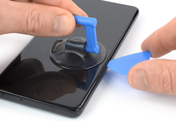
– Get yourself a suction handle and secure it to the bottom edge of the back cover, as close to the edge as possible.
– Use that handy suction handle to lift the back cover gently, creating a small gap between the back cover and the frame.
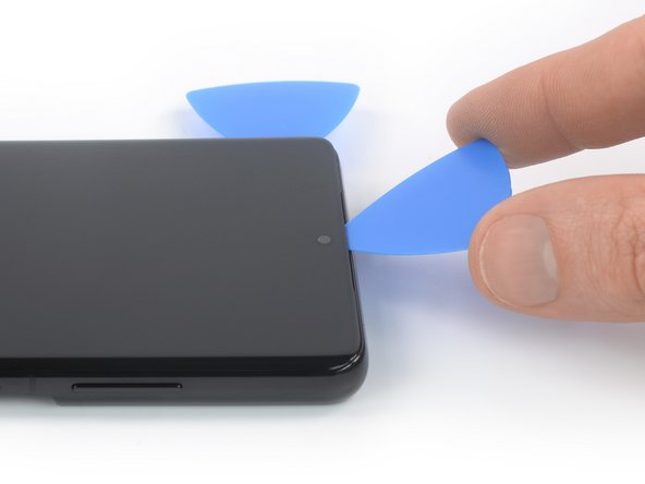
– Take an opening pick and insert it into the gap you made, like a pro.
– Glide that opening pick to the bottom left corner to slice through the adhesive with ease.
– Let the opening pick chill there to make sure the adhesive doesn’t try to reseal itself. Groovy, right?
Tools Used

Step 3


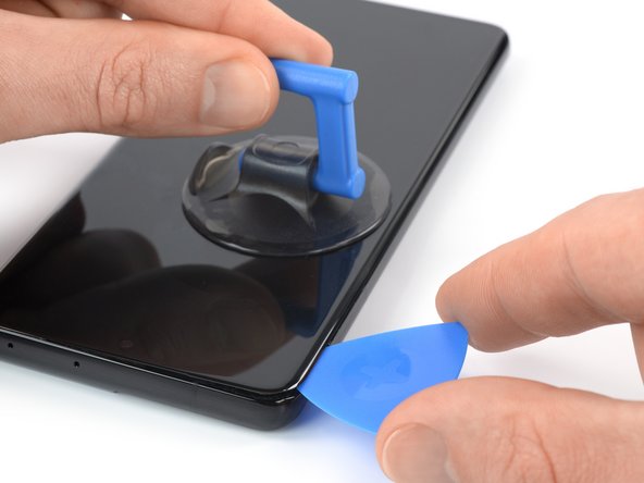
– Pop in a second opening pick at the bottom edge of your phone.
– Gently slide that opening pick over to the bottom right corner to cut through the adhesive like a pro.
– Keep those opening picks in place to ensure that adhesive doesn’t try to sneak back in and seal things up again.
Step 4


If the adhesive is giving you a hard time and feels tough to slice through, it’s probably cooled off a bit. Give your iOpener a quick two to three-minute warm-up to get things back on track!
– Pop in a third opening pick down at the bottom right corner of your device.
– Gently slide the opening pick along the right edge of your device to smoothly slice through the adhesive.
– Hang on to the opening pick in the top right corner to make sure the adhesive doesn’t stick back together.
Tools Used
Step 5


Careful now! When working around the camera assembly, just slide the tip of the opening pick (about 4-5mm) to avoid any camera mishaps. If you need help, you can always schedule a repair.
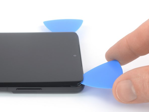
– Slip a fourth opening pick under the top right corner of your phone.
– Glide the pick along the top edge to cut through the adhesive.
– Keep the pick in the top left corner to stop the adhesive from sticking back.
Step 6


When you’re working near the power button, use just the tip of the opening pick (around 3-4mm) to steer clear of the power and volume button flex cable. If you need help, you can always schedule a repair.
– Slide in a fifth opening pick right under the top left corner. It’s like giving your device a little nudge!
– Now, gently glide the pick along the left edge of the back cover to cut through that stubborn adhesive. You’ve got this!
Step 7


– First things first, let’s get that back cover off!
– Now, while you’re putting everything back together:
– Here’s a handy tip: it’s a great idea to power on your phone and check that everything’s working like a charm before you seal it up. Just remember to turn it off completely before diving back in.
– Got some adhesive bits hanging around? Grab a pair of tweezers or just use your fingers to gently remove them.
– Next up, take some high concentration (over 90%) isopropyl alcohol and give any sticky residue a good wipe.
– If you’re using custom-cut adhesives, make sure to follow the guide provided.
– And if you’re rolling with double-sided tape, just check out the corresponding guide.
Step 8


– Wedge an opening pick just under the left bottom end of the NFC antenna and charging coil assembly.
– Gently glide the opening pick along the bottom left edge of the assembly to detach it from the battery.
Step 9


– Slide an opening pick under the bottom edge of the NFC antenna and charging coil assembly. You’re doing great!
– Gently glide the opening pick along the bottom of the assembly to detach it from the loudspeaker. Keep it up!
Step 10


– Grab a spudger and gently disconnect the charging coil by lifting the connector straight up from its socket.
Tools Used

Step 11


– Gently pop off the NFC antenna connector with a spudger. Easy peasy! If you need help, you can always schedule a repair.
Tools Used
Step 12

– Grab your trusty Phillips screwdriver and carefully unscrew those five 3.9 mm-long screws that are holding down the NFC antenna and charging coil assembly. You’ve got this!
Step 13


– Grab a trusty pair of tweezers or just your fingers, and gently lift out the NFC antenna and charging coil assembly. You’ve got this!


Step 15

– Grab your trusty Phillips screwdriver and tackle those four 3.9 mm-long screws holding the loudspeaker assembly in place. You’ve got this!


Step 17


– First up, let’s get that loudspeaker assembly out of the way. It’s time for a little makeover!
– When you’re putting everything back together, don’t forget to add fresh adhesive where needed after giving those areas a good clean with some isopropyl alcohol (>90%). You’re doing great!
Step 18


If you’re not looking to take out the motherboard or swap the battery, feel free to breeze past this step and jump right into the next one!
– Grab your trusty spudger and gently lift the display flex cable connector straight up from its socket. You’ve got this!
Tools Used
Step 19


– Grab your trusty spudger and carefully unhook the main and interconnect flex cables from the motherboard. Just gently pry their upper connectors straight up from their sockets and let the magic happen!
Tools Used
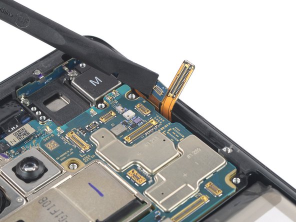
Step 20


– Grab a spudger and pop the interconnect flex cable off the daughterboard by gently prying up the bottom connector.
– Use your fingers or a pair of tweezers to carefully detach the interconnect flex cable. If you need help, you can always schedule a repair
Tools Used
Step 21


– Grab your trusty spudger and gently nudge that main flex cable right off the daughterboard by lifting its bottom connector straight up from the socket. You’ve got this!
– Now, with a little finesse, use your fingers or some tweezers to delicately pull away the main flex cable. Easy peasy!
Tools Used
Step 22

– Grab your trusty Phillips screwdriver and take out the four 3.9 mm screws that are holding the earpiece speaker and laser AF module assembly in place. If you need help, you can always schedule a repair
Step 23


– Grab your trusty spudger and gently lift the laser AF module and earpiece speaker flex cables by prying the connectors straight up from their cozy little sockets. You’ve got this!
Tools Used
Step 24


– Using a pair of blunt nose tweezers, gently grasp the bottom right corner of the earpiece speaker and laser AF module assembly and lift it upwards with care.
– Once you’ve got a good grip, remove the earpiece speaker and laser AF module assembly.
Step 25


Handle those cables with care! Give them a gentle bend, but no sharp folds, to keep them in tip-top shape.
– Time to get those in-display fingerprint and antenna flex cables to loosen up a bit! Use a spudger and gently pry those connectors straight up from their socket.
– Give those connectors a little friendly nudge to the side to liberate the motherboard.
Tools Used


Step 27


– Grab your trusty spudger and gently lift the power button flex cable by prying the connector straight up from its cozy socket.
– Now, with a gentle touch, bend the connector to the side to liberate the motherboard. You’re doing great!
Tools Used
Step 28

– Grab your trusty Phillips screwdriver and get ready to tackle that 3.9 mm-long screw holding the camera module in place. Let’s get it done!
Step 29


Be careful not to mess up those flex cables hanging around the motherboard while you tackle this part of the process!
– Slide a spudger under the top edge of the motherboard, right next to the vibration motor. You’ve got this!
– Gently use your spudger to lift the motherboard by angling it downwards and giving it a little twist to the side. Keep it smooth and steady!
Tools Used
Step 30


Be gentle when removing parts and watch out for any twisted flex cables to avoid snags!
– Gently lift out the motherboard with care.
Step 31

The adhesive on the Galaxy S21 Ultra display is super strong, so get ready to heat up that iOpener multiple times to tackle the display removal process like a boss! Don’t sweat it if you don’t have an iOpener – a hair dryer, heat gun, or hot plate can also do the trick, just remember not to go overboard with the heat. You’ve got this!
– Get cozy with your device and gently warm it up using an iOpener. Give it a nice 5-minute spa treatment.
Step 32

Make sure to use just the tip of the opening pick (around 4-5 mm) during this process. We want to avoid getting tangled up with that sneaky in-display fingerprint cable or risking any accidental tears. You’ve got this!
If your screen is looking like it just survived a rock concert, slapping on a layer of clear packing tape might just do the trick for the suction cup to stick. Got some super strong tape? That could work even better than the suction handle! And if you’re really in a bind, a little superglue on that suction cup can help it cling on for dear life. Remember, if you need help, you can always schedule a repair.
– When you feel the screen getting toasty, pull out your nifty suction handle and place it right on the left edge, near the bezel!
– Now gently lift that screen with your suction sidekick, making some room between the glass and the metal frame for our next move.
– Time for the opening pick to join the party! Slide it into that gap between the midframe and the screen.
– Drag that pick all the way up to the top left corner to cut through the adhesive.
– Don’t forget, leave your opening pick in the game to keep that adhesive from rushing back together!
Tools Used
Step 33


– Pop in a second opening pick at the top left corner and glide it down to the bottom left corner of the screen to cut through the adhesive.
– Keep the opening pick in place to stop the adhesive from sticking back together.
Step 34

When you’re slicing near the front-facing camera, just sneak in the tip of your opening pick (about 2-3 mm) to keep that camera safe and sound – we don’t want any smudges or scratches on that little beauty!
– Pop a third opening pick into the top left corner of your screen like a pro!
– Gently glide that pick along the top edge of your phone to cut through the adhesive like butter.
– Keep the opening pick in place—it’s your adhesive blocker, preventing any sneaky resealing!
Step 35


– Hey there, let’s spice things up a bit!
– Gently slip in your trusty opening pick right under the screen’s top right corner.
– Carefully move the pick down the right edge to effortlessly cut through the adhesive.
– Keep that pick snug in its spot to make sure the adhesive doesn’t decide to reseal itself.
Step 36


– Pop in a fifth opening pick at the bottom right corner of the screen. You’ve got this!
– Gently glide that opening pick along the bottom edge to slice through the last bits of adhesive like a pro!
Step 37


– Gently guide the fingerprint flex cable through the little opening in the midframe. You’ve got this!
Step 38

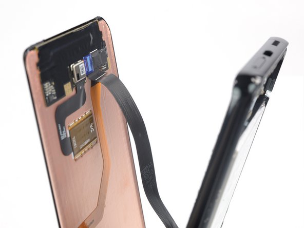
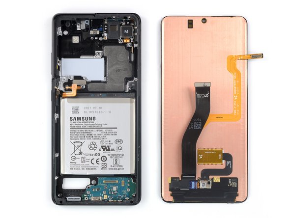
– Gently guide that display flex cable through the midframe gap and say goodbye to your old screen!
– Take a moment to compare your shiny new replacement part with the original—don’t forget to move over any leftover bits from your old screen if needed.
– After giving everything a good clean with some isopropyl alcohol (90% or higher, please!), add fresh adhesive where it counts!
– As you piece everything back together, keep this guide nearby, especially if you’re using a pre-cut adhesive card. You’ve got this!


