Samsung Galaxy S21+ Vibration Motor Replacement Guide – DIY Tutorial
Duration: 45 minutes
Steps: 28 Steps
Hey there, it looks like we’re working on the incredible SM-G996B/DS model. Time to bring out your repair skills and get this device back in top shape! If you need a hand, feel free to schedule a repair with us.
Ready to give your Samsung Galaxy S21 Plus a little love? This guide will help you swap out the vibration motor like a pro! We’re working with the SM-G996B/DS (international) model here, but if you’ve got a different version, just keep an eye out for an extra antenna cable tucked away in the midframe. Remember, if you skip replacing those adhesive seals during reassembly, your device will still work fine, but it might lose some of that sweet water protection. So, make sure to grab some replacement adhesive to keep everything snug and secure when you’re putting it all back together. And if you need help, you can always schedule a repair!
Step 1

– Get your trusty iOpener ready and place it on the back cover for a solid three minutes. This will help loosen the adhesive beneath, making your repair journey smoother and easier!
Tools Used

Step 2


– Grab a hold of a trusty suction handle and attach it snugly to the lower edge of the back cover.
– Elevate the back cover using the suction handle to create a teeny gap between it and the frame.
– Carefully slip an opening pick into the gap that you’ve just crafted.
– Gently guide the opening pick to the lower left corner to smoothly cut through the adhesive.
– Let the opening pick stay put to keep the adhesive from sneaky resealing maneuvers.
Tools Used

Step 3


– Time to bust a move! Insert that second opening pick at the bottom edge of your phone.
– Slide the opening pick to the bottom right corner like a boss to slice through that pesky adhesive.
– Keep those opening picks in place, they’re the real MVPs and will make sure that adhesive stays put.
Step 4


If the adhesive is putting up a bit of a fight and seems tough to slice, it probably just got a bit too cool. Give your iOpener a go for two to three minutes to warm things back up.
– Pop in a spunky third opening pick down at the bottom right corner of your phone.
– Gently slide the opening pick along the right edge of your device to cut through that sticky adhesive.
– Let that opening pick chillax in the top right corner to keep the adhesive from sticking back together.
Tools Used
Step 5


When you’re getting close to the camera assembly, just use the tip of the opening pick (about 4-5 mm) to keep everything safe and sound—no smudges or damage allowed!
– Pop a fourth opening pick right under the top right corner of your phone.
– Gently glide that opening pick along the top edge to cut through the adhesive like a pro.
– Keep the opening pick in the top left corner to stop the adhesive from sealing back up.
Step 6


– Slide a fifth opening pick under the bottom left corner, like you’re tucking in a cozy blanket.
– Now, glide that opening pick along the left edge of the back cover to cut through the last bits of adhesive. You’re almost there!
Step 7


– Time to pop off that back cover! Get it off so we can get to the good stuff.
– As you put things back together, keep it cool and collected!
Step 8


Handle that battery with care—no poking or prodding! A battery that gets punctured or bent could spring a leak of some nasty stuff or even cause a little heat drama.
Watch out for the cable sneaking under the charging coil. Take your time and ease off the pick if it gets snagged on the cable—slow and steady wins the race!
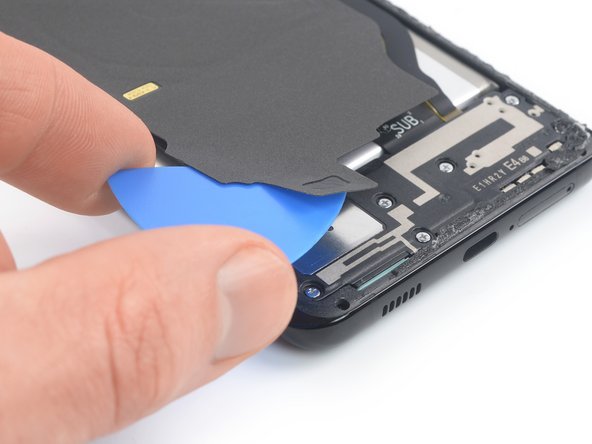
– Slip an opening pick under the lower left corner of the NFC antenna and charging coil setup.
– Gently glide the pick along the left base to detach it from the battery.
Step 9

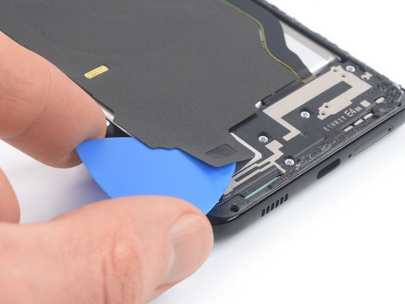
– Slide an opening pick gently under the bottom edge of the NFC antenna and charging coil assembly. It’s like giving it a little lift!
– Now, carefully glide that pick along the bottom of the assembly to help it break free from the loudspeaker. You’re doing great!
Step 10


– Grab your trusty spudger and gently lift the charging coil connector straight up from its socket. You’ve got this!
Tools Used


Step 12

– Grab your trusty Phillips screwdriver and tackle those five 3.9 mm-long screws holding down the NFC antenna and charging coil assembly. You’ve got this!
Step 13


– Grab a trusty pair of tweezers or just your fingers, and with a gentle touch, pop out the NFC antenna and charging coil assembly. You’ve got this!
Tools Used


Step 15


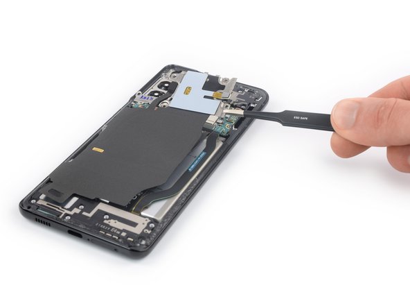
– Alrighty, folks! Let’s get this display flex cable disconnected. Use your spudger to gently pry that upper connector straight up from its little socket. Easy-peasy, lemon-squeezy! And if you get stuck, remember: you can always schedule a repair!
Tools Used
Step 16

– Grab your trusty spudger and gently lift the main and interconnect flex cables off the motherboard. Just pry those upper connectors right up from their sockets—easy peasy!
Tools Used
Step 17

– Grab your trusty Phillips screwdriver and get ready to tackle those seven 3.9 mm-long screws holding the earpiece speaker assembly in place. You’ve got this!
Step 18

– Grab your trusty spudger and gently nudge that earpiece speaker cable loose by lifting the connector straight up from its cozy socket. You’ve got this!
Tools Used
Step 19


– Slide your trusty spudger under the lower left corner of the earpiece speaker assembly. You’ve got this!
– Gently use your spudger to lift the earpiece speaker assembly up and away. Take it nice and easy!
Tools Used
Step 20


– Gather your courage, buddy, and carefully remove that pesky earpiece speaker assembly with some tweezers or your trusty fingers. Once you’ve finished the tear down, make sure to clean up any old adhesive and get ready to put your new assembly together with some fresh adhesive. Just don’t forget to blow off any dust and apply that glue in all the right spots! If you need some help along the way, you can always schedule a repair.
Tools Used

Step 22


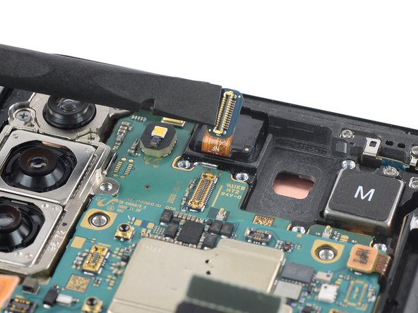
Just a friendly reminder: When navigating this step, please be gentle with the cable – no sharp folds, just smooth bends to keep your connection in tip-top shape! Need some extra help? No worries, you can always schedule a repair.
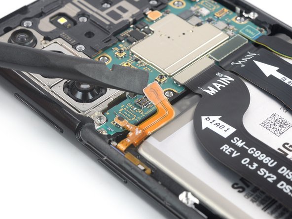
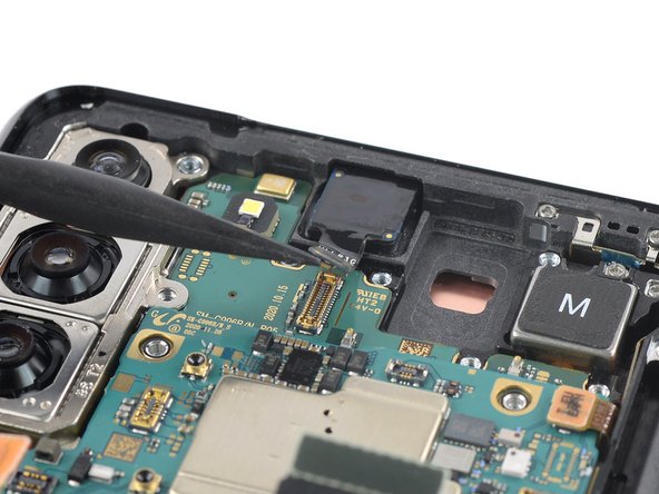
– Grab a spudger and gently disconnect the power button flex cable by lifting the connector straight up from its socket.
– Take your trusty spudger and delicately bend the flex cable to the side to ensure it stays safe and sound during the motherboard removal.
Tools Used
Step 23

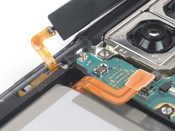
Be gentle with those cables, folks! Smooth bends only, no sharp folds – we want to keep ’em in tip-top shape. If you need a little extra guidance, just check out our in-house repair skills via schedule a repair!
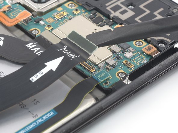
– Go ahead and rock that spudger to gracefully disconnect the power antenna flex cable by gently prying the connector straight up from its socket.
– Take your spudger and with a touch of finesse, bend the flex cable to the side to ensure its safety during the motherboard removal.
Tools Used
Step 24

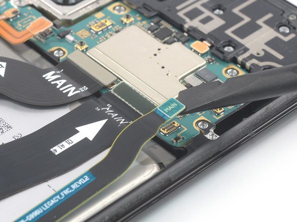
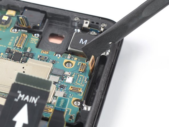
Be extra careful not to let those pesky cables get tangled with the motherboard assembly while you’re working your magic. We wouldn’t want any cable mishaps to cramp your style!
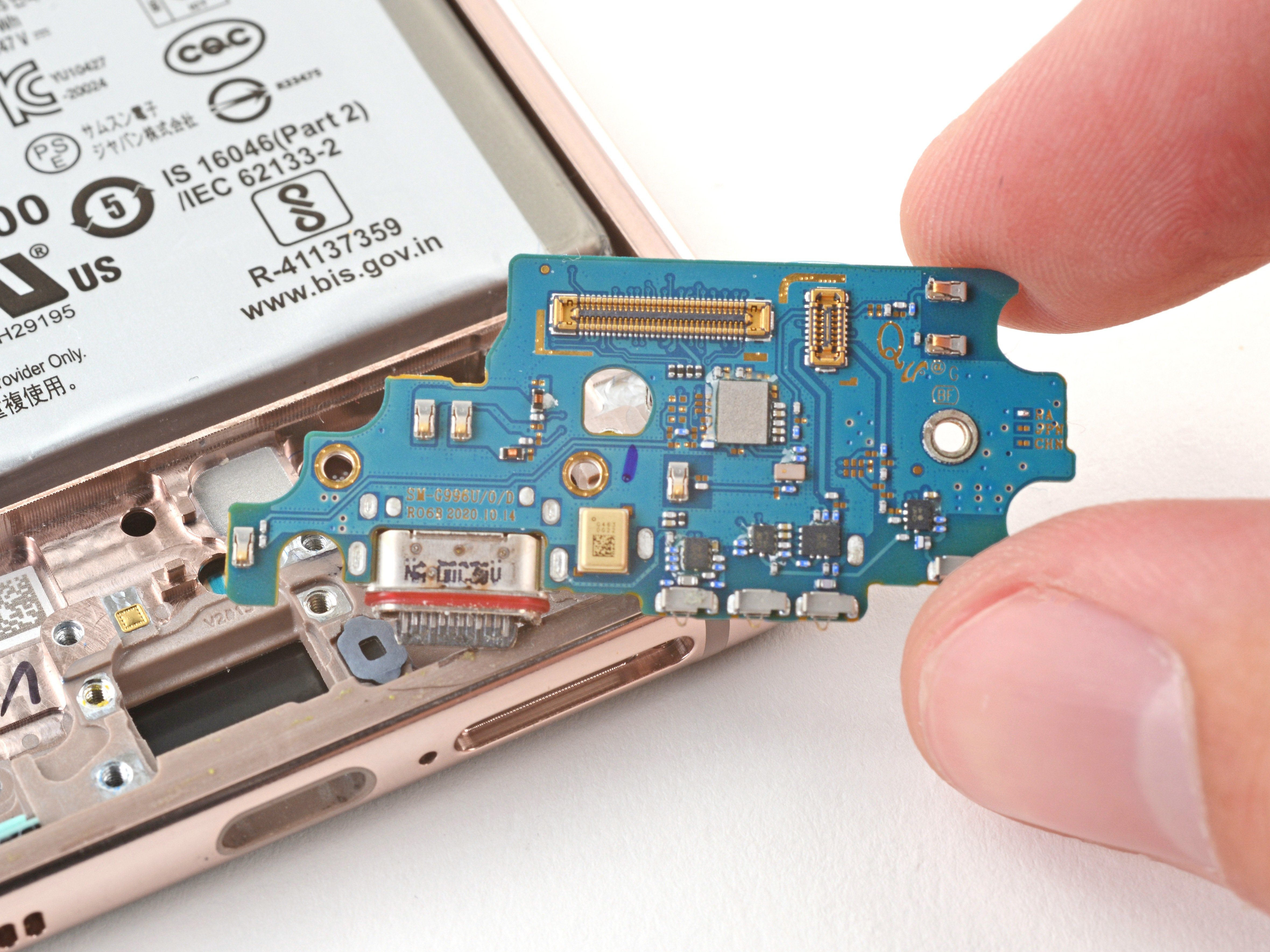
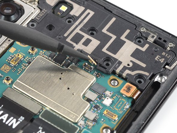
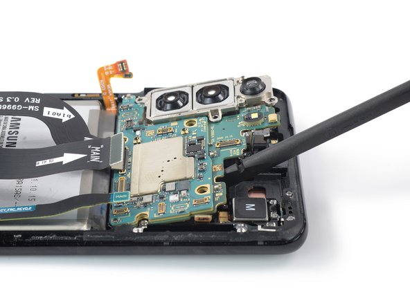
– Slide a spudger gently under the top edge of the motherboard assembly, right next to the vibration motor.
– Lift the motherboard assembly using the spudger.
Tools Used
Step 25
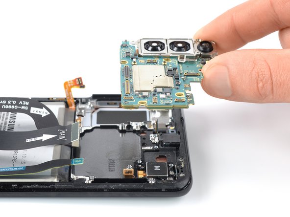

– Gently detach the motherboard assembly along with the rear cameras, taking care to keep everything safe and sound.


Step 28


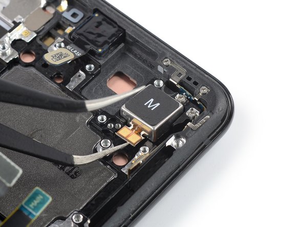
– Get your pair of trusty tweezers ready and gently lift the vibration motor out of its cozy spot, giving it a nice little vacation.
– When putting everything back together, show some love by adding fresh adhesive in the right places, like giving your device a refreshing makeover with isopropyl alcohol (>90%).
Tools Used