How to Replace Samsung Galaxy S21+ Motherboard Step-by-Step Guide
Duration: 45 minutes
Steps: 27 Steps
SM-G996B/DS
Get ready to level up your repair game with this rad guide on how to replace the motherboard on your Samsung Galaxy S21 Plus! Don’t worry, even if you’re a beginner, you’ve got this. Just follow our step-by-step tutorial and you’ll be a pro in no time. If you need any help along the way, you can always schedule a repair with our awesome team at Salvation Repair.
Step 1

– Get your iOpener ready and give the back cover a nice little warm hug for about three minutes. This will help loosen up the adhesive underneath.
Tools Used

Step 2


– Grab your handy dandy suction handle and stick it to the back cover, right on the edge. Now, pull that back cover up just a smidge, and let’s get our opening pick in there! Slide that pick down to the bottom left corner, and let it do its magic. And hey, if you need a hand, schedule a repair!
Tools Used

Step 3


– Pop in another opening pick down below on your phone.
– Gently glide it to the bottom right edge to cut through the sticky stuff.
– Keep those opening picks in place to make sure the sticky situation doesn’t come back.
Step 4


If the adhesive is giving you a hard time and feels tough to cut, it’s probably cooled off a bit. Grab your iOpener and give it a warm-up for two to three minutes to get things back on track.
– Alrighty then, pal up that bottom right corner with a new fella opening pick and slide him along the right edge for a smooth slice, only this time let him chill in the top right corner lest that adhesive should snap back in place!
Tools Used
Step 5


When you’re getting up close and personal with the camera assembly, just slide in the tip of your opening pick (about 4-5 mm) to keep that camera safe and sound—no smudges or damage allowed!
– Get that fourth opening pick under the top right corner of your phone.
– Gently slide the opening pick along the top edge to slice through the adhesive.
– Keep that opening pick in the top left corner to make sure no resealing happens.
Step 6


– Slide a fifth opening pick under the bottom left corner like you’re slipping a note to a friend.
– Gently glide the pick along the left edge of the back cover to cut through the last bits of adhesive. You’re almost there!


Step 8


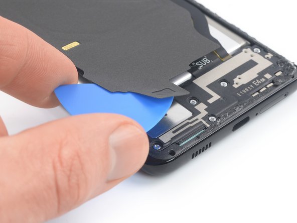
– Slide an opening pick gently under the left bottom corner of the NFC antenna and charging coil assembly. You’re on your way!
– Carefully glide that opening pick along the bottom left edge of the assembly to detach it from the battery. Keep it smooth and steady!
Step 9

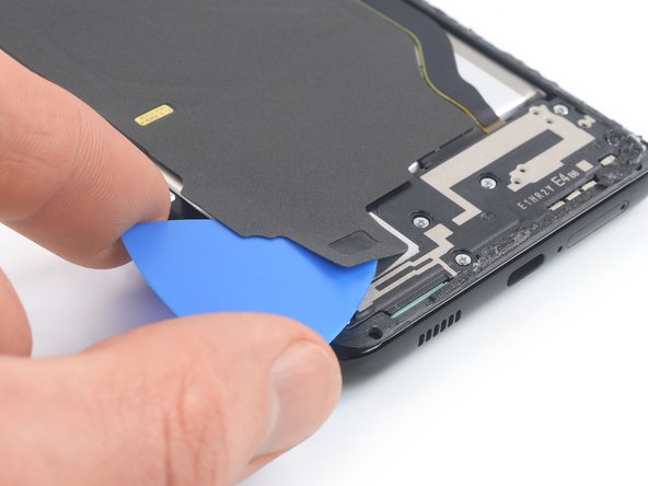
– Sneak an opening pick right beneath the bottom edge of the NFC antenna and charging coil squad.
– Gently glide the opening pick along the base of the squad to detach it from the chatty speaker.
Step 10


– Get ready to rock ‘n’ roll by using a spudger to disco the charging coil. Just gently pry the connector straight up from its cozy socket.
Tools Used


Step 12

– Grab your trusty Phillips screwdriver and go ahead and unscrew those five 3.9 mm-long screws that are holding the NFC antenna and charging coil assembly in place. You’ve got this!
Step 13


– Gently use tweezers or your fingers to lift out the NFC antenna and charging coil assembly with care. You’ve got this!

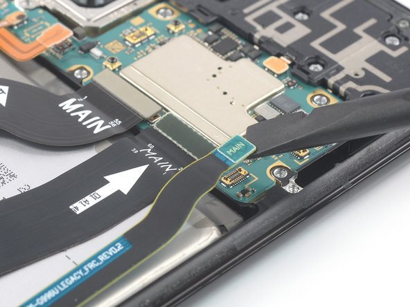
Step 15


– Alrighty, let’s disconnect that display flex cable – just use a spudger and give its upper connector a gentle nudge straight up from its home. If you need help, you can always schedule a repair!
Tools Used
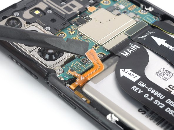
Step 16

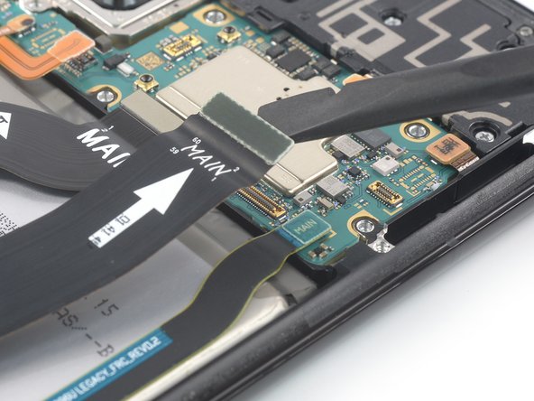
– Get ready to channel your inner gadget guru! Unleash your tool-taming talents and have fun as you gently pry up the upper connectors of the main and interconnect flex cables using your trusty spudger. This will disconnect them from the motherboard’s sockets. If you need help, you can always schedule a repair.
Tools Used
Step 17

– Grab your trusty Phillips screwdriver and get ready to tackle those seven 3.9 mm-long screws holding the earpiece speaker assembly in place. You’ve got this!
Step 18

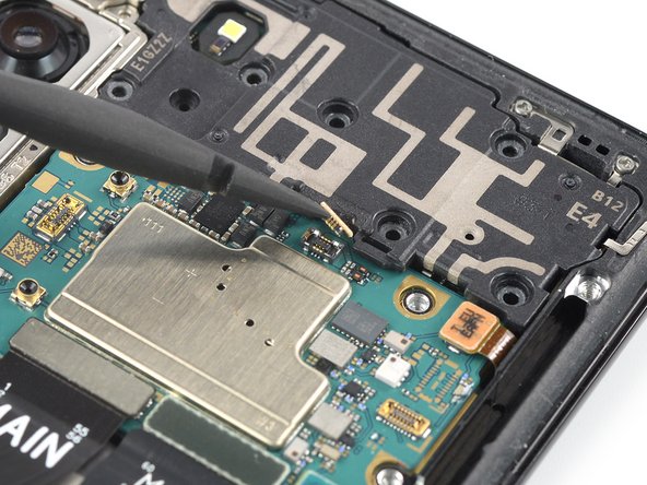
– To effortlessly free the earpiece speaker cable, delicately use a spudger to lift the connector straight up out of its socket.
Tools Used
Step 19


– Slip a spudger beneath the cool bottom left edge of the awesome earpiece speaker assembly.
– Gently leverage the earpiece speaker assembly like a champ with your spudger.
Tools Used
Step 20


– Get ready to rock and roll with your repair skills! Gently remove the earpiece speaker assembly using either a pair of tweezers or your trusty fingers.
– Time to put your adhesive skills to the test – add some fresh adhesive where needed after giving the areas a good scrub with isopropyl alcohol (>90%)!
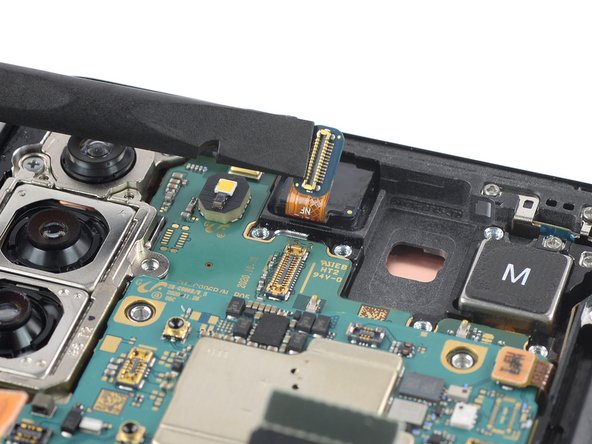

Step 22


Hey there! Remember to keep it chill with that cable, no sharp folds, just a friendly bend to keep it in tip-top shape! If you need help, you can always schedule a repair.
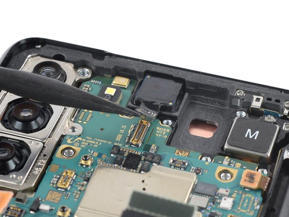
– Time to work some magic! Gently use a spudger to give the power button flex cable a little breather. Pry the connector straight up from its socket like a champ!
– Let’s show that flex cable some love! With your trusty spudger, carefully bend the flex cable to the side, making sure to give it some space during the motherboard removal dance.
Tools Used
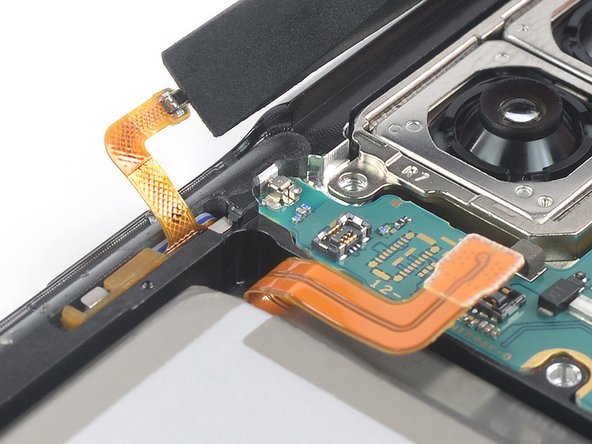
Step 23

As you tackle this step, remember to keep the cable bending gentle and easy—no sharp folds, please! We want to keep that cable happy and healthy.
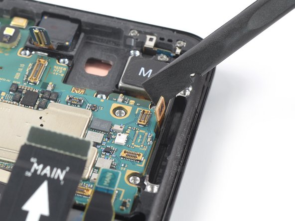
– Grab your trusty spudger and gently lift the power antenna flex cable by prying the connector straight up from its cozy little socket. Easy peasy!
– Now, with your spudger in hand, carefully wiggle the flex cable to the side. This will help avoid any mishaps while you work on removing the motherboard. You’ve got this!
Tools Used
Step 24
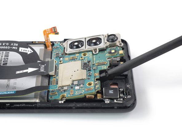

Keep those cables cozy and untangled from the motherboard assembly while you work your magic! We want to avoid any cable mishaps during the removal process.
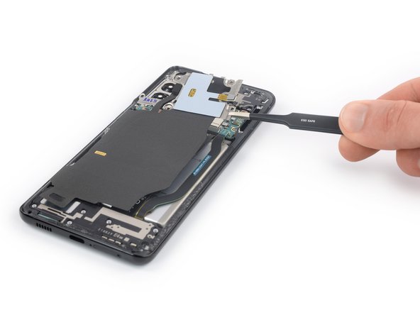
– Alrighty, tech fixers! Let’s get glamoring! 🌟 Slide that super spudger under the top edge of your motherboard assembly while it’s chillin’ next to the vibration motor. Then, with a fun pop, pry up that motherboard assembly! 💥✨ If you need help, you can always schedule a repair.
Tools Used
Step 25
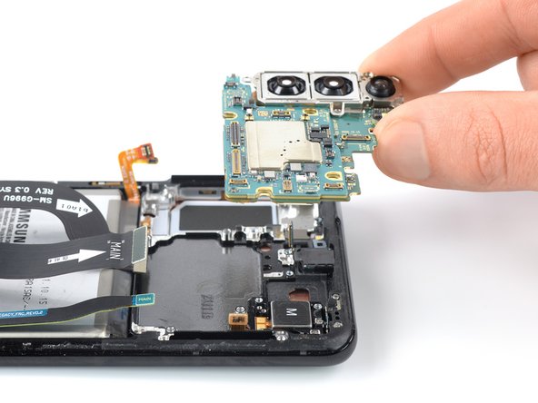

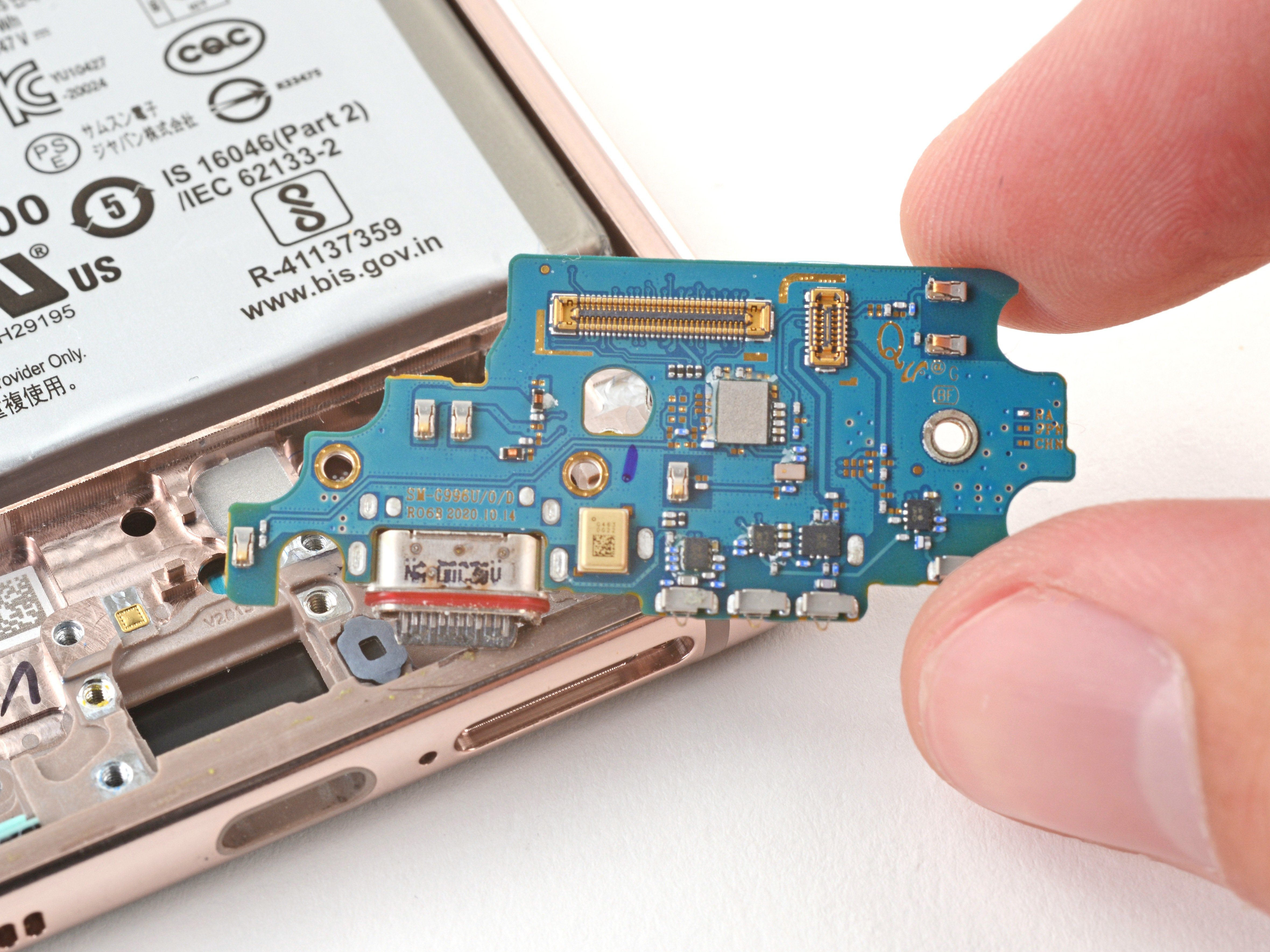
– Gently take out the motherboard assembly along with the rear cameras, and you’re one step closer to wizardry!
Step 26
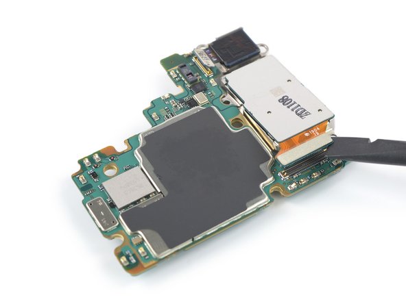

– Get your spudger ready to disco! Disconnect the ultra wide camera flex cable by rocking its connector up straight from its socket.
– Get groovy with that spudger and disconnect the wide and tele camera assembly by rocking its connector straight up from its socket.
Tools Used
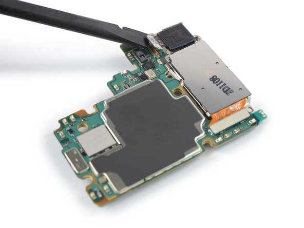
Step 27


– Easily separate the camera assembly from the motherboard using a pair of tweezers or simply your finger.
– When putting things back together, make sure to add some fresh adhesive in the right spots after cleaning those areas with isopropyl alcohol (>90%).