Samsung Galaxy S21 5G Daughterboard Replacement Tutorial
Duration: 45 minutes
Steps: 34 Steps
Hey there, make sure to have some fun with it and drain that battery down below 25% before you start getting into the guts of your phone. Stay safe and let’s get this show on the road!
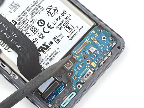
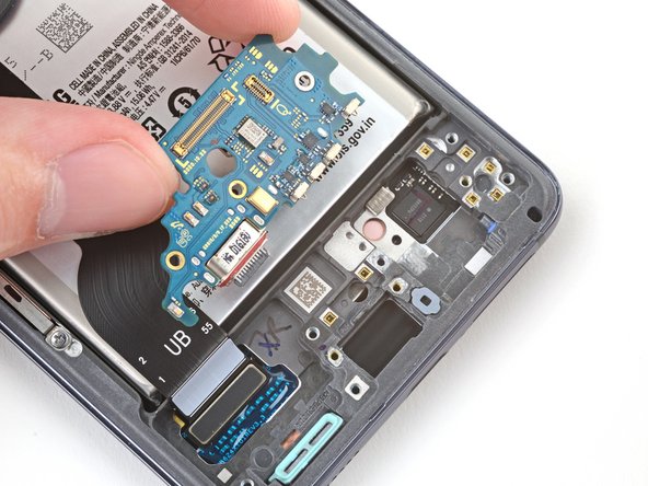
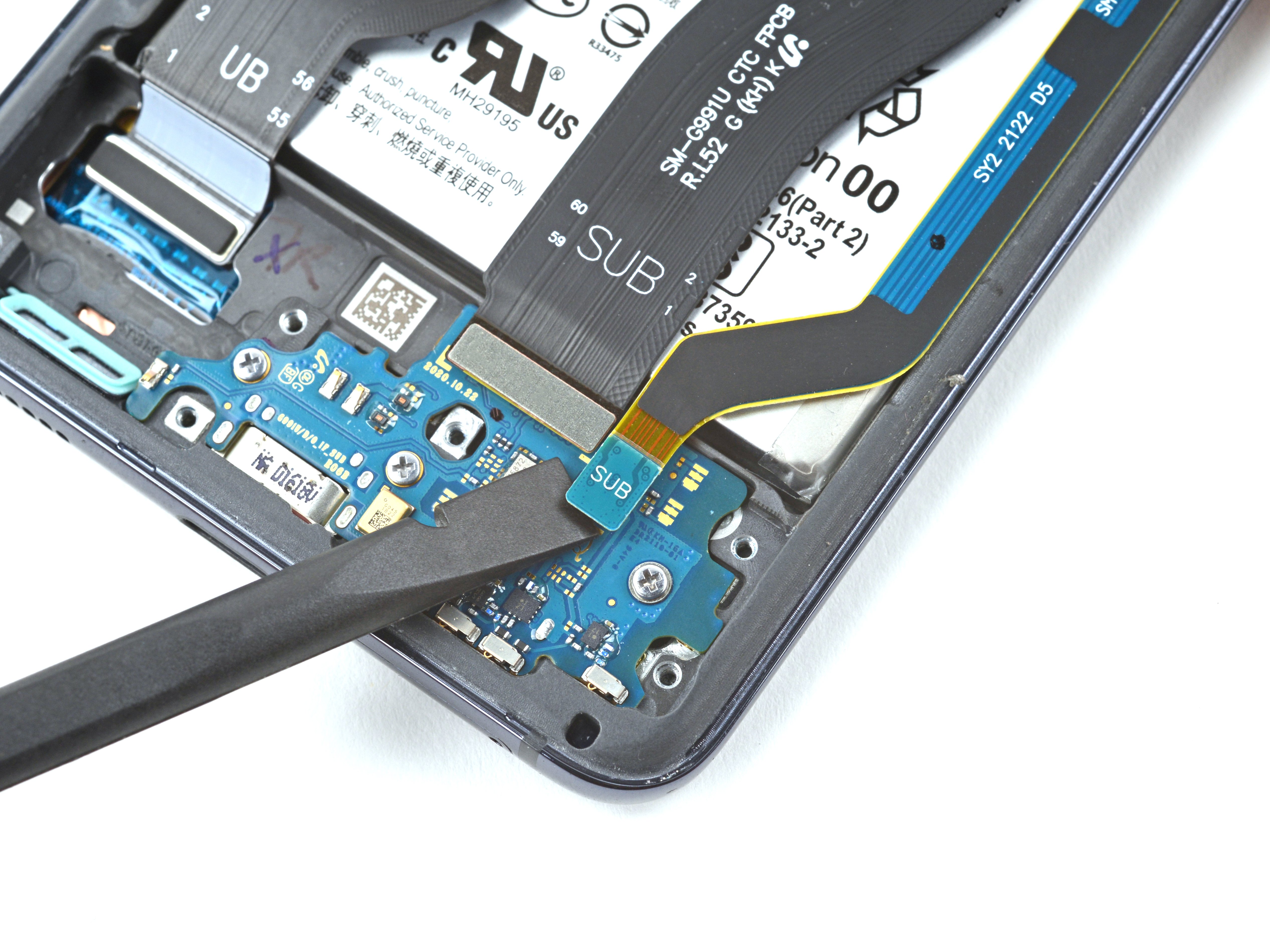
Get ready to dive into some fun phone repair! This guide will help you tackle the daughterboard removal or replacement on your Samsung Galaxy S21. Remember, safety first! Make sure your battery is below 25% before you start disassembling your device. This little step helps prevent any unexpected thermal surprises if the battery gets a bit too adventurous during the repair. If you see any swelling, take extra precautions. Now, a heads-up: the daughterboard and USB-C charging port are joined at the hip, so replacing one means you’ll be swapping out both. You don’t have to remove both interconnect cables before tackling the daughterboard, but doing so might just make your life a bit easier. Some images show those cables being replaced one at a time, but if you follow our steps in order, you’ll be removing them like a pro. And if you’re ever feeling stuck, remember, you can always schedule a repair for some extra help!
Step 1
If you accidentally poked the SIM eject tool into a microphone hole, no worries! Chances are, the microphone is safe and sound.
– Got a SIM eject tool, a bit, or a paper clip? Time to work some magic!
– Put that tool in the SIM card tray hole along the bottom edge of your phone.
– Give it a gentle push to say ‘hello’ to the SIM card tray.
– Gently take out the SIM card tray and voilà!
Step 2
Make sure to give your device a good night’s rest by turning it off completely before getting started.
– Get cozy with an iOpener and gently place it on the lower edge of the back cover for a quick two-minute chill session.
Tools Used
Step 3
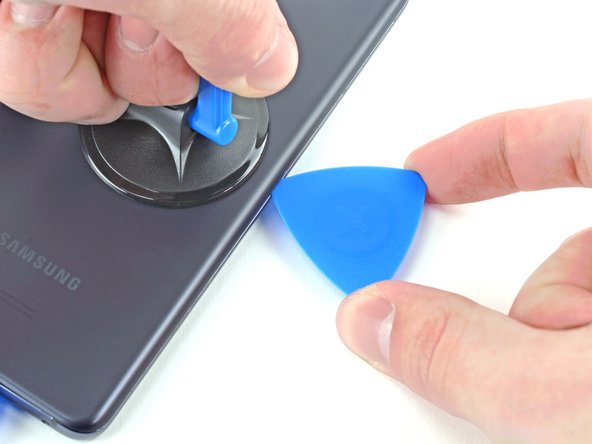
– Hey, you’re on a roll! It’s time to take that suction cup action, right about the center of the bottom part. Press on as if it’s your personal quest! Then, oh so gently, slip in your trusty opening pick — you got this!
Step 5
– Warm up the left edge of the back cover with a heated iOpener for a cozy two minutes.
Tools Used
Step 6
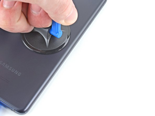
– First things first, place a suction cup on the back of your phone, aiming for the center of the left edge like a pro!
– Now, give that suction cup a good, steady pull – enough to create a little gap between the back cover and the frame. You’ve got this!
– Next up, slide an opening pick into that gap and let’s keep moving forward!
Step 7
– Gently glide an opening pick along the left edge towards the bottom left corner to trim away the adhesive.
– Keep the pick inserted to prevent the adhesive from sticking back together.
Step 8
– Warm up the iOpener and gently apply it to the right edge of the back cover for two minutes. You’ve got this!
Tools Used
Step 9
– Time to show that phone who’s boss! Place a suction cup right in the middle of its right edge.
– Give that suction cup a good workout! Pull it up with a firm, steady hand to create some space between the back cover and the frame.
– Here comes the opening pick to the rescue! Slide it into the gap you’ve made. You’re a pro at this!
Step 10
– Gently glide an opening pick back and forth along the right edge of the back cover to break that adhesive seal.
– Keep the pick in place to stop the adhesive from sticking back together.
Step 11
Get groovin’ at the corners, but save that top-left spot for the camera, ya dig? If you need help, you can always schedule a repair
– Get ready to rock and roll,Top right corner time! Spin that opening pick around and make that phone’s day!
Step 12
– Gently glide the top opening pick as close to the camera shell as a penguin slides on ice!
– Give that left-edge pick a repeat performance like a pro!
Step 13
– Warm up an iOpener and gently place it on the camera shell for a couple of minutes.
Tools Used
Step 14
If this method doesn’t do the trick, just pop to the next step for a different approach; if all else fails, feel free to skip the following step.
– Give that back cover a spin to the left like you’re dancing your way to success! This creates a sneaky little gap between the camera shell and the frame.
– Slide in an opening pick like a pro, showing that gap who’s boss.
Step 15
Handle this method with care, as there’s a chance you might crack the plastic back cover. Stay cautious and keep that phone intact!
– Carefully slide those two picks towards the camera shell, tucking them under the corners of the back cover next to the camera shell.
– Now, give those picks a little dance back and forth along the bridge between the back cover and the camera shell until you’ve opened up a nice gap between the camera shell and the frame.
Step 16
– Gently slide an opening pick in between the camera shell and the frame to break that stubborn adhesive seal.
Step 17
Watch out for that sneaky plate on the back cover around the phone’s flash! It’s known to make picks play hard to get.
– Take a moment to slice through the extra adhesive hanging out to the right of the camera. You’ve got this!
Step 18
– Align the tip of your opening pick with the flash of your phone.
– Gently slide the pick in, being careful to steer clear of the flash’s plate.
– Slice through the adhesive just to the right of the camera.
Step 19
– Get ready to rock and roll by removing the back cover.
– Time to put things back together:
Step 20
While you’re diving into this repair adventure, be sure to keep tabs on each screw, and remember to return each one to its original cozy home.
– Grab your trusty Phillips screwdriver and work some magic by taking out those five screws that are holding the motherboard bracket snug to the frame. They are 4 mm long and playing hard to get, but you’ve got this!
Step 21
Hold your horses, don’t remove that bracket just yet! It’s still hugging the wireless charging coil.
– Grab a trusty pair of tweezers and gently lift up to unclip the motherboard bracket from the frame. You’ve got this!
Tools Used
Step 22
– As you delicately maneuver the motherboard bracket with tweezers or your nimble fingers, employ a spudger to gently lift the battery press connector. Remember, it’s all about finesse and precision!
– When it comes to reattaching press connectors like the one before you, ensure a perfect alignment as you firmly press one side down until it audibly snaps into place. Repeat this dance on the remaining side, avoiding any pressure on the center. A misaligned connector risks bending the pins, leading to irreversible damage. So, let’s keep it aligned and locked in place for a seamless repair.
Step 23
– While keeping the motherboard bracket out of your way, grab your trusty spudger and gently pry up to disconnect the wireless charging coil’s press connector. You’ve got this!
Tools Used
Step 24
The wireless charging coil is held in place with a bit of light adhesive magic.
– Gently coax the wireless charging coil away from the phone using your fingers—think of it as giving it a little hug goodbye!
– When putting everything back together, start by securing the motherboard bracket screws. This will help you neatly position the charging coil. Once that’s done, give the coil a firm press down to make sure it sticks like a champ!
Step 25
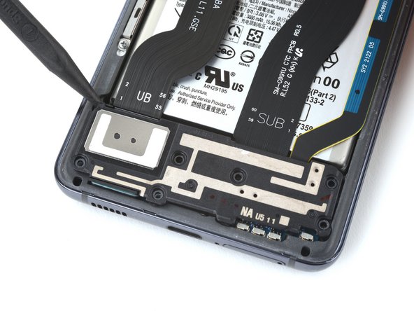
– Grab your trusty Phillips screwdriver and get ready to tackle this task! Unscrew those six 4 mm screws that are holding the loudspeaker snugly to the frame. You’ve got this!
Step 29
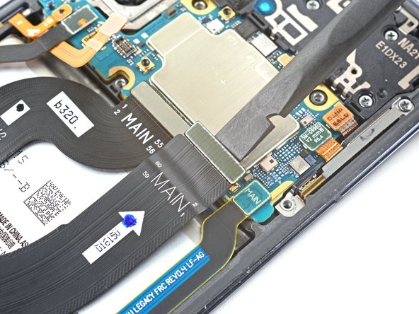
– Alrighty then! Time to be a mini MacGyver and remove that primary interconnect cable. Grab your trusty tweezers or maybe just your lucky fingers, and let’s get that cable outta there. If you’re feeling a bit nervous, just remember you’ve got the best team at Salvation Repair for backup schedule a repair!
Tools Used
Step 33
– Grab your trusty Phillips screwdriver and get ready to tackle those pesky screws! Carefully unscrew the three 3.5 mm screws holding that daughterboard snugly to the frame. You’ve got this!


