Samsung Galaxy S20 Ultra Rear Facing Camera Module Replacement Guide
Duration: 45 minutes
Steps: 43 Steps
Hey there! Just a quick heads-up: be careful while you’re diving into this repair. Follow the steps closely and take your time. If you need a hand, you can always schedule a repair.
Get ready to dive into the world of DIY repair! This guide will walk you through the steps to take out and swap the rear-facing camera module for your Galaxy S20 Ultra. Inside this module, you’ll find all four rear-facing cameras snugly fit along with the frame that keeps them safe. If you’re just looking to replace a specific camera, this guide’s got your back too! Just a heads up, this process involves removing the motherboard, so make sure you’re prepared. And don’t forget, you’ll need some replacement adhesive to wrap things up nicely. If you need help, you can always schedule a repair.
Step 1


– Grab a SIM card eject tool, a bit, or even a straightened paperclip and gently slide it into the tiny hole on the SIM tray, which you’ll find at the top edge of your phone, right next to the plastic antenna band.
– Give it a firm push to pop that tray out!
Tools Used

Step 2


– Hey there! Let’s tackle this SIM card situation together, and you’ll be on your way to full connectivity in no time. First things first, let’s safely remove the SIM card tray, yeah? And when you’re ready to plug it back in, make sure it’s facing the right direction, gotta keep it oriented properly, you know what I mean? Oh, and don’t forget the little rubber gasket! That bad boy keeps your device safe and sound from water and dust. If it’s not there or looks a bit iffy, just replace it or the whole tray to keep everything in tip-top shape. If you need a hand, you can always schedule a repair!
Step 3

First things first, give your phone a little break—unplug it and power it down before diving in.
– Warm up your iOpener and press it against the bottom edge of the back cover for a solid two minutes.
Tools Used

Step 4


– Get ready to give your phone a little lift on the back side. Place a suction cup towards the center at the bottom and pull with some muscle. Let’s create a tiny space between the back and the frame.
– It’s pick time! Slide in an opening pick right into that space you just made. We’re one step closer to unveiling the magic inside.
Step 5


– Gently glide the pick along the bottom edge, back and forth, to cut through that sticky adhesive like a pro.
– Keep your trusty opening pick in the seam to stop the adhesive from sealing up again.
Step 6

– Warm up that iOpener and give the left edge of the back cover a cozy two-minute hug!
Tools Used
Step 7


Since we’re working with some snug fits here, don’t be surprised if it takes a few tries to get it just right!
– Place a suction cup on the back of your phone, aiming for the sweet spot near the center of the left edge.
– Give that suction cup a good, steady tug to create a cozy little gap between the back cover and the frame.
– Slide the point of an opening pick into that gap and get ready to work your magic!
Step 8


– When the pick successfully sneaks under the glass’s edge, give it a little tilt downwards and gently slide it in further to completely free the back cover’s adhesive.
Step 9


– Gently slide the pick down towards the bottom edge of your phone to break free the back cover’s sticky grip.
– Keep your pick tucked under the left edge of the glass near the bottom of the device to stop that adhesive from making a comeback.
Step 10


– Slide another pick under the center of the left edge of the back cover. We’re just getting started!
– Carefully glide that pick towards the top of the device to break free the back cover’s adhesive. Go slow and steady!
– Once you’ve made some progress, leave your pick tucked under the left edge of the glass near the top. This will keep the adhesive from making any sneaky attempts to reseal.
Step 11

– Warm up your iOpener and give the right edge of the back cover a cozy hug for two minutes.
Tools Used
Step 12


– Grab a suction cup and stick it to the back of your phone, aiming to get it as close to the center of the right edge as you can.
– With a nice, firm grip, pull on that suction cup! You’re looking to create a little gap between the back cover and the frame.
– Now, take an opening pick and gently slide it into that gap you just made.
Step 13


– Gently slide the pick down towards the bottom edge of your phone to break free the back cover’s sticky grip.
– Keep your pick tucked under the right edge of the glass near the bottom of the device to stop that adhesive from making a comeback.
Step 14


– Slide another pick right under the center of the back cover’s right edge. You’re doing great!
– Gently glide that pick towards the top of the device to break free the back cover’s sticky bond. Keep it steady!
Step 15

– Warm up the top edge of the back cover with a heated iOpener for a cozy two minutes.
Tools Used
Step 16


The glass at the corners of the back cover has a bit of a curve and can be a little fragile. Take your time during this step to keep your back cover safe and sound!
– Gently ease the pick into the right edge of your device and glide it around the top right corner like a pro.
– Keep slicing along the top edge until you’ve completely freed the back cover from the adhesive’s grip.
Step 17


– Lift that back cover up slowly, like a magician’s reveal! Use those opening picks to slice any remaining adhesive – it’s like cutting the cutsest of cute bread! And don’t worry about the reassembly, just follow the steps and you’ll have it done in a snap. If you need help, you can always schedule a repair.
Step 18


– Grab your trusty spudger and gently pry up to disconnect that wireless charging coil connector. You’ve got this!
Tools Used

Step 19


– Grab a trusty pair of tweezers and carefully lift the wireless charging coil away from the device. Easy does it!
– Now, go ahead and remove that wireless charging coil. You’re doing great!
– When it’s time to put everything back together, start by reconnecting the wireless charging coil connector first. This will help you get it just right. Then, give the rest of the coil a firm press to make sure it sticks. You’ve got this!
Tools Used

Step 20

– Get out your handy Phillips #00 screwdriver and let’s tackle those five 3.9 mm-long screws holding the motherboard bracket in place. Time to show those screws who’s boss!
Tools Used

Step 21

– Grab a trusty pair of tweezers and gently unclip that motherboard bracket. Time to set it free!
Tools Used


Step 23

– Grab your trusty Phillips #00 screwdriver and get ready to tackle those five 3.9 mm-long screws holding the loudspeaker and lower midframe in place. You’ve got this!
Tools Used


Step 25
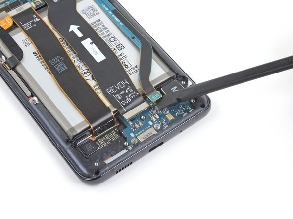

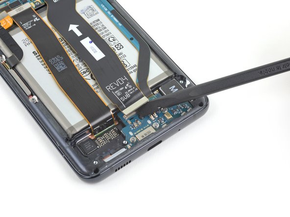
– Get ready to channel your inner repair superhero and use a spudger to elegantly pry up and disconnect the main and auxiliary flex cables from the daughterboard located near the lower part of the device.
– When it’s time to re-attach these press connectors, approach it like a thoughtful artist – align them carefully and apply gentle pressure on one edge until you hear that satisfying click, then do the same on the opposite end. Avoid pressing down on the center, as we don’t want any pin bending mishaps. Stay sharp and keep it steady!
Tools Used
Step 26


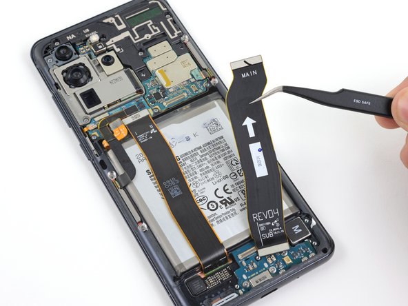
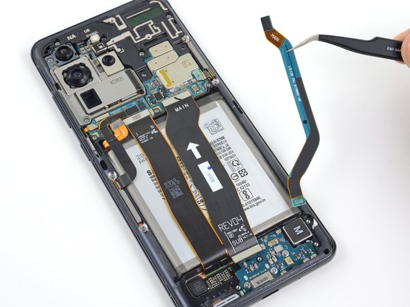
– Get your spudger ready to gracefully lift and disconnect the main and auxiliary flex cables from the motherboard.
Tools Used


Step 29


– Gently pry up and disconnect the main display flex cable from the motherboard. You’ve got this!
Step 30


– Carefully lift and bend the display and the left 5G antenna flex cables out of the way, making some room for the motherboard and battery to breathe.
Step 31

– Grab your trusty Phillips #00 screwdriver and get ready to tackle those four 3.9 mm-long screws holding down the upper midframe. You’ve got this!
Tools Used

Step 33

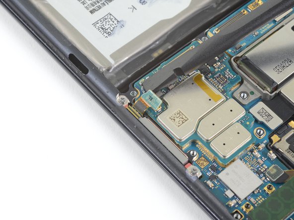
– Gently lift and disconnect the right 5G antenna flex cable from the motherboard. It’s a simple move, just like peeling a banana!
– Grab a pair of tweezers and give that cable a little nudge to move it out of the way of the motherboard. You’re doing great!
Tools Used
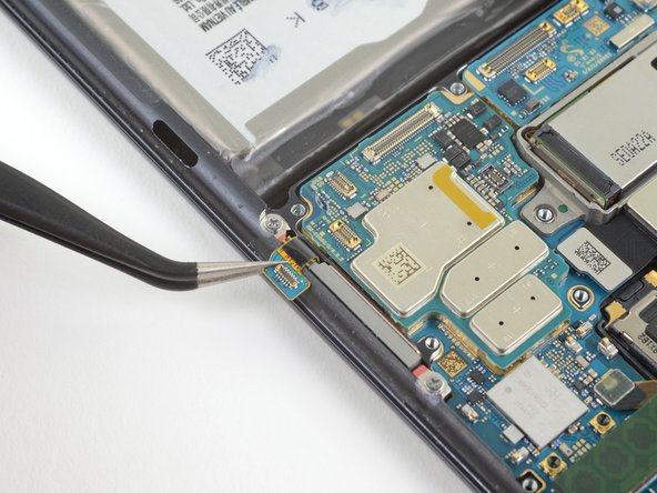
Step 34

– Gently lift and detach the side button flex cable from the motherboard. You’ve got this!
– Carefully bend the cable to keep it clear of the motherboard. Easy peasy!
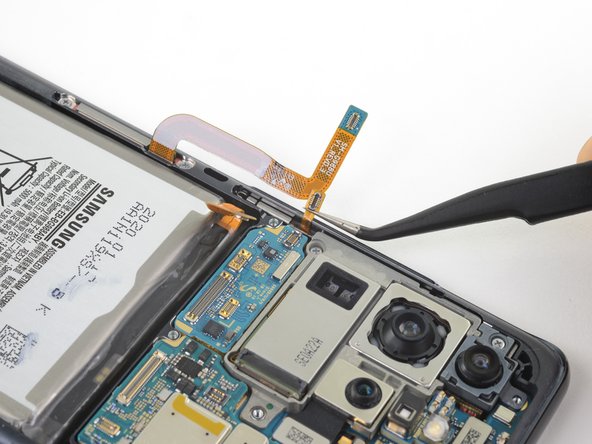
Step 35

– Gently lift and unplug the front-facing camera flex cable from the motherboard. You’ve got this!
– Carefully bend the cable to keep it out of the motherboard’s way. Easy peasy!
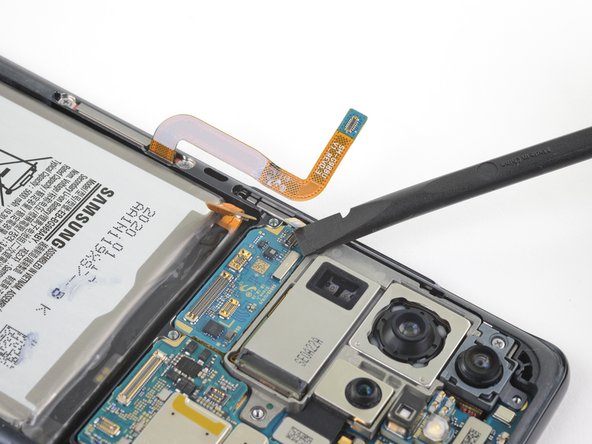
Step 36

– Get ready to dance as you gently lift and detach the high-flying 5G antenna cable from its motherboard stage.
Step 37

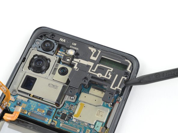
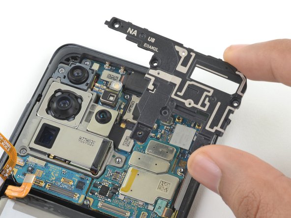
– Grab your trusty spudger and gently pry up the corner of that 5G millimeter wave antenna module. You’ve got this!
– Now, it’s time to carefully remove the 5G antenna module. Easy peasy!
– When you put it all back together, remember to reconnect the 5G antenna connector first. This way, it’ll fit perfectly into place. Then, give the rest of the antenna module a good press down to make sure it’s securely attached.
Tools Used
Step 38

– Grab your trusty Phillips #00 screwdriver and let’s get to work! Remove those two 3.9 mm-long screws that are holding the motherboard and camera assembly in place. You’re doing great!
Tools Used
Step 39


– Gently slide the tip of your spudger into the bottom left corner of the motherboard assembly and give it a little nudge to pop it free from the phone’s body.
– Carefully lift out the motherboard assembly.
Tools Used

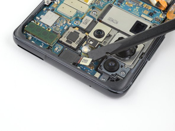
Step 41

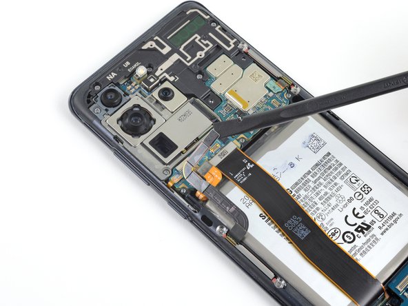
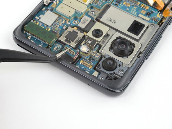
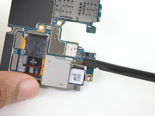
– Gently lift and unplug the telephoto and wide-angle camera connectors from the motherboard. If you need help, you can always schedule a repair.
Step 42

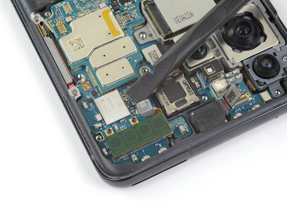
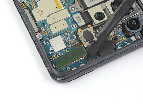
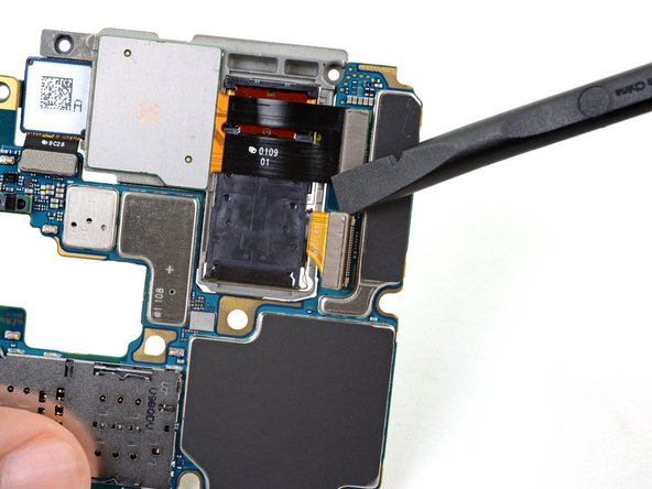
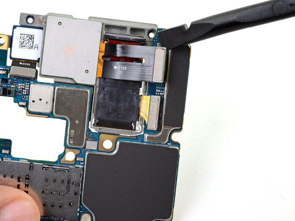
– Time to flip that motherboard assembly over! Now, gently pry up and disconnect the depth sensor connector from the motherboard. You’ve got this!
Step 43

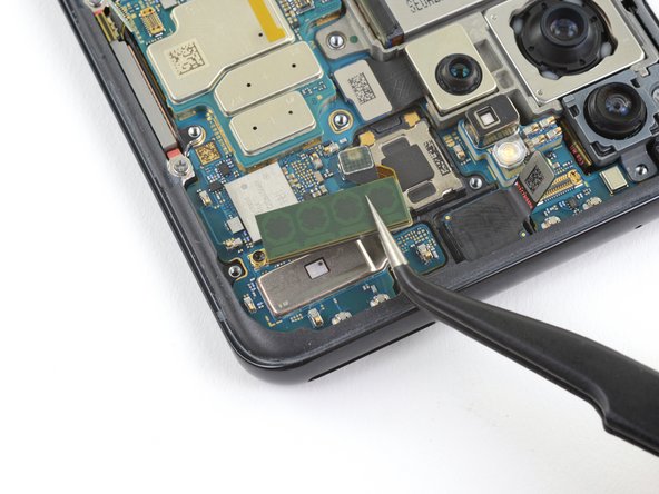
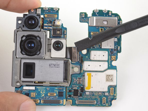
When swapping out individual cameras, you might have to gently detach and shift over some of the current cameras to your spiffy new setup.
– Grab a cup of coffee and cheerfully bid farewell to the rear facing camera module by removing it gently from its place.


