Samsung Galaxy S20 FE 5G Motherboard Replacement Guide DIY Tutorial
Duration: 45 minutes
Steps: 28 Steps
Hey there! Just to make sure you’re ready to take on this repair challenge, why not grab a buddy or two to help with the fun? If you need help, you can always check out our repair services to get the job done together!
Ready to dive into some phone magic? Follow this guide to swap out the motherboard in your Samsung Galaxy S20 FE 5G. Just remember, you’ll want some replacement back cover adhesive to get everything snug and secure when you’re done. If you need help, you can always schedule a repair.

Step 2

No worries, mates! You might’ve poked the mic hole by mistake, but fret not. Your mic’s probably hunky-dory and still ready to rock those impromptu karaoke nights.
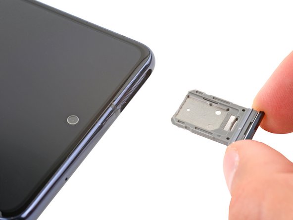
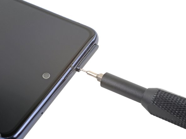
– Grab your trusty SIM eject tool, a bit, or even a straightened paper clip, and give that SIM card tray hole on the top edge of your phone a solid press until the tray pops out like a surprise party!
– Now, gently lift out the SIM card tray and give yourself a high five—you’ve got this!
Step 3

– Warm up your trusty iOpener and gently press it against the bottom edge of the back cover for a cozy two minutes.
Tools Used

Step 4
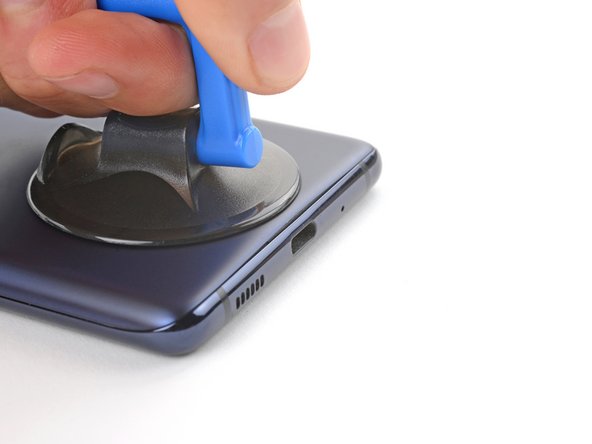

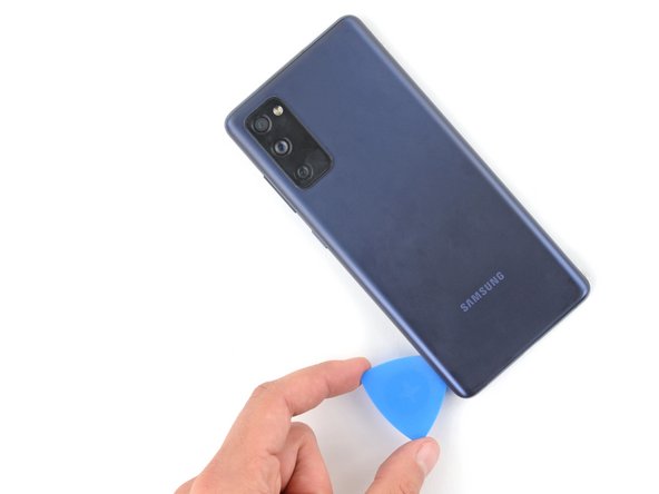
– Stick a suction cup right in the middle of the bottom edge of the back cover, almost at the very edge.
– Give that suction handle a good, firm tug to make some breathing room between the cover and frame.
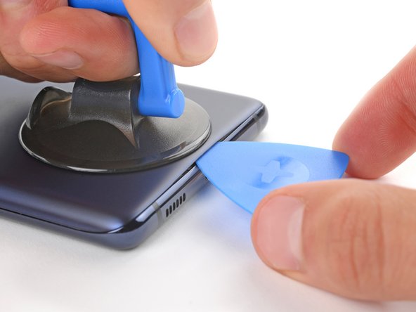
– Slide an opening pick into the space you’ve created.
Tools Used

Step 5

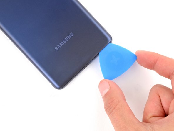
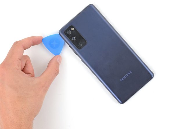
– Gently glide the opening pick along the bottom edge to slice through the sticky stuff holding the back cover in place.
– Keep that opening pick snugly in the bottom right corner to keep the adhesive from playing tricks and resealing itself.
Step 6

– Gently warm up a trusty iOpener on the right side of the back cover for about two minutes.
Tools Used
Step 7

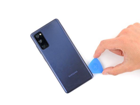
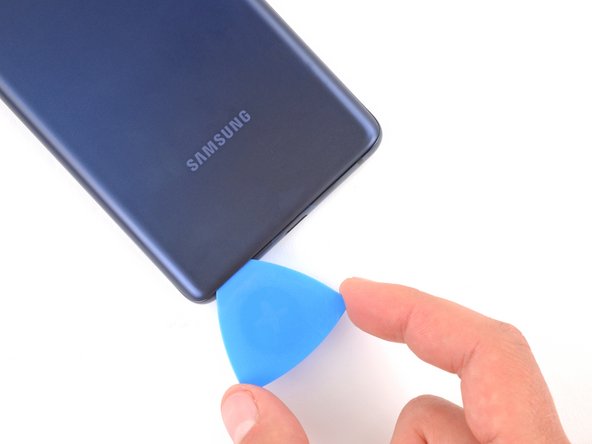
– Gently glide the opening pick around the bottom right corner and continue along the right edge to carefully cut through the adhesive.
– Keep that opening pick snugly in place in the top right corner for the next steps.
Step 8

– Warm up a heated iOpener and give it a cozy spot on the top edge of the back cover for a solid two minutes.
Tools Used
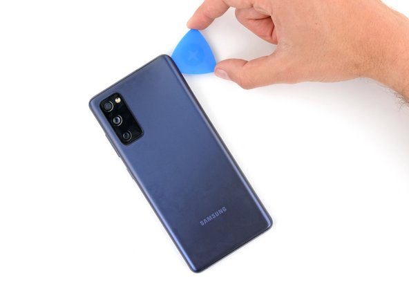
Step 9

– Gently wiggle the opening pick around the top right corner and glide it along the top edge to break that adhesive seal. You’re doing great!
– Keep that pick snug in the top left corner to keep things open and ready for action.
Step 10

– Warm up that iOpener and give it a cozy hug against the left edge of the back cover for two whole minutes. That’s like a mini spa day for your device!
Tools Used
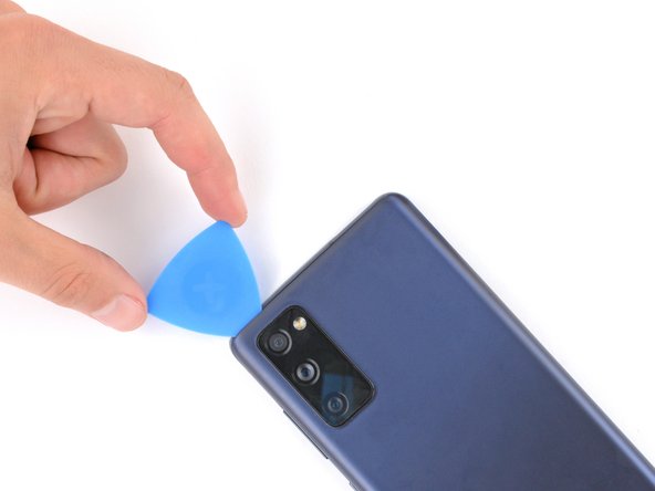
Step 11

– Gently glide the opening pick around the top left corner and continue along the left edge to smoothly cut through the last bits of adhesive.
Step 12


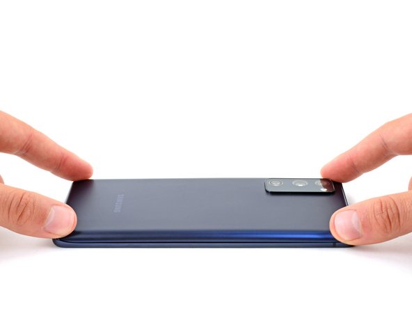
– Let’s pop off that back cover!
Step 13

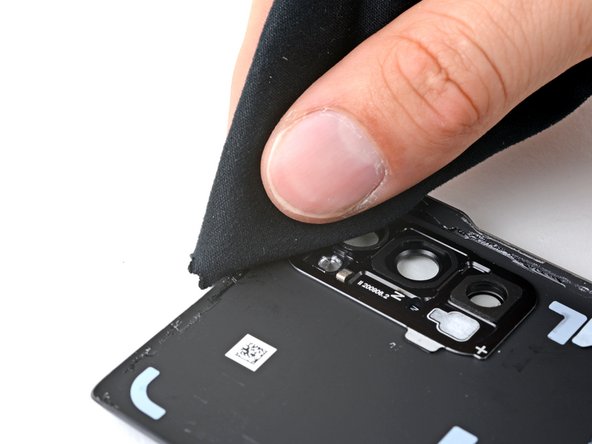
– Now’s a great time to give your device a little pep talk! Power it on and check if everything’s working like a charm before you seal it up. Just remember to power it down completely when you’re ready to dive back into the repair.
– If you’re putting your old back cover back on, you’re almost there!
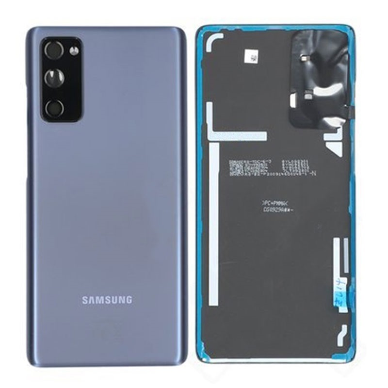
– For those rocking a brand new back cover, just peel off those liners and give it a firm press around the edges to snug it up to the frame.
Step 14

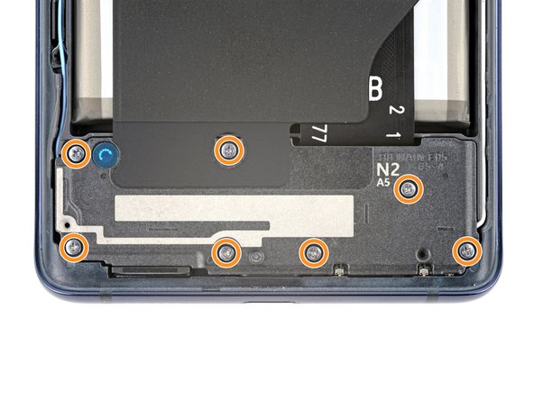
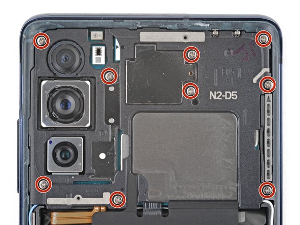
The wireless charging setup consists of the motherboard cover, the wireless charging coil, and the loudspeaker, all snugly held together with some handy graphite tape. Just remember to take them out as a single unit for a smoother experience!
– Grab your trusty Phillips screwdriver and get ready to unscrew those 16 little screws holding the wireless charging assembly in place! You’ve got this!
Step 15

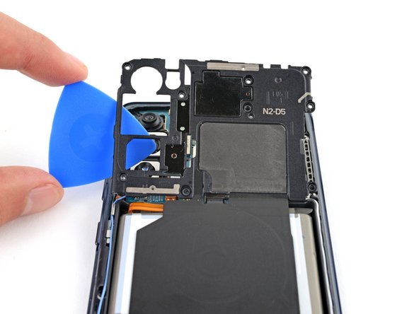
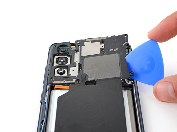
– Slide a pick under the bottom right corner of the motherboard cover. Give it a little twist to set it free.
– Take the pick and work your magic on the clips holding the cover in place. Twist away!
– Now, head to the bottom left side with your trusty opening pick. Twist and shout as you unclip those final bits.
– When it’s time to put things back together, show that cover who’s boss! Press firmly all around to lock in those clips.
Step 16

– Slip the motherboard cover back into place for easy access to the battery and wireless charging press connectors located along the bottom edge of the motherboard.
Step 17

To securely reattach press connectors, gently align them and press down on one side until you hear a satisfying click. Repeat the same on the opposite side. Avoid pressing the center to prevent any mishaps. Remember, little adjustments can save you from big hiccups later on.
– Now, let’s gently use the flat end of a spudger to carefully lift and detach both the battery and wireless charging press connectors from the motherboard. If you need assistance, you can always schedule a repair.
Tools Used

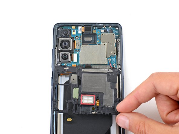
Step 18

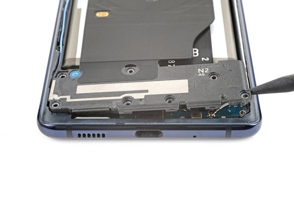
– Gently wedge the point of a spudger between the bottom left corner of the loudspeaker and the frame, like you’re giving it a little tickle.
– Now, give a light pry to pop up those clips holding the left edge of the loudspeaker in place. It’s like letting your friend out of a hug – nice and easy!
– Next up, give the bottom right corner of the loudspeaker a little nudge to free up the last of those pesky clips.
– When you’re putting everything back together, don’t forget to press down firmly around the edges of the loudspeaker. Let’s make sure those clips know they’re securely home!
Tools Used
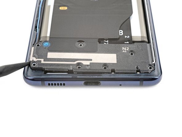
Step 19
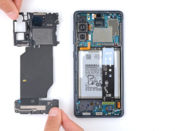
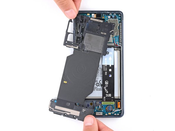

– Let’s get that wireless charging assembly out of there!
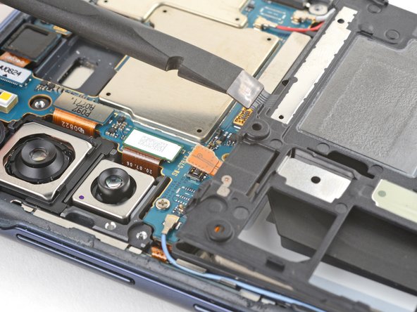
Step 20

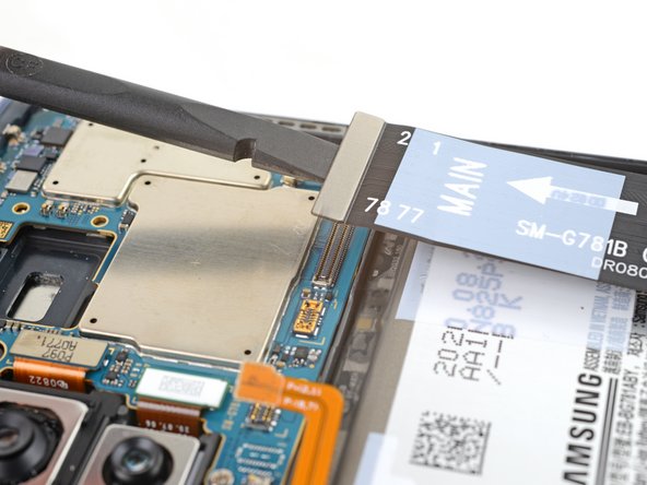
– To easily disconnect the interconnect cable press connector from the motherboard, gently lift using the flat end of a spudger. Stay cool and steady with this step!
Tools Used
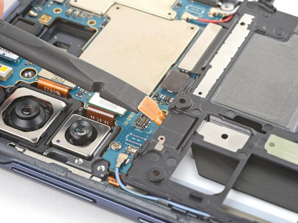
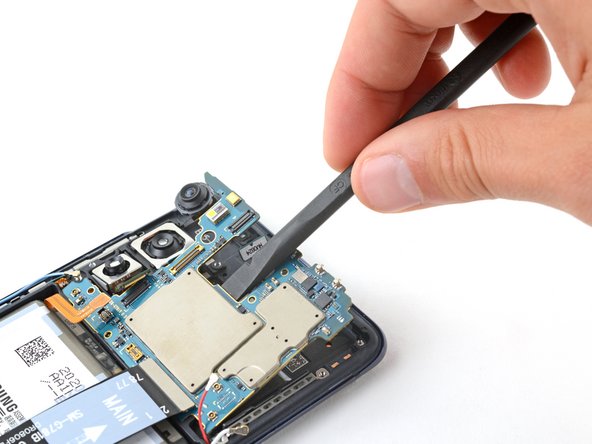
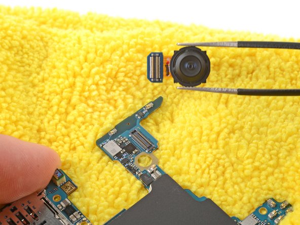
Step 21
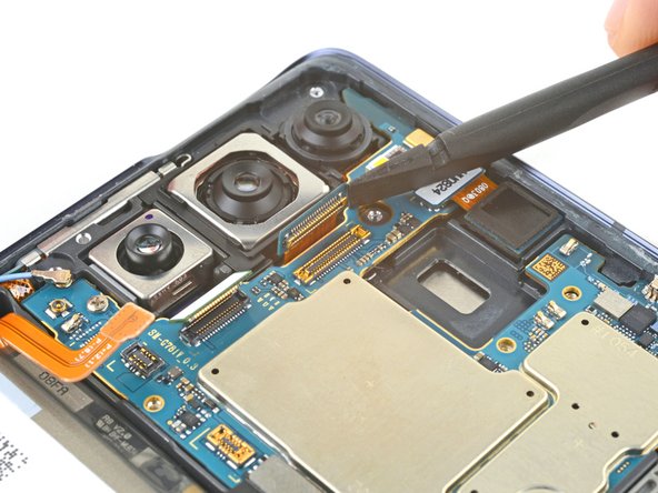

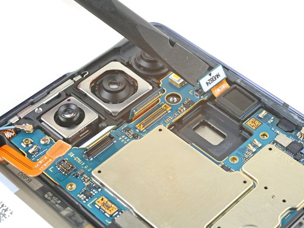
– Grab your trusty spudger and gently use the flat end to disconnect those three camera press connectors. You’ve got this!
Tools Used
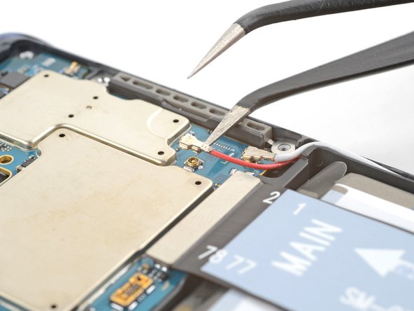

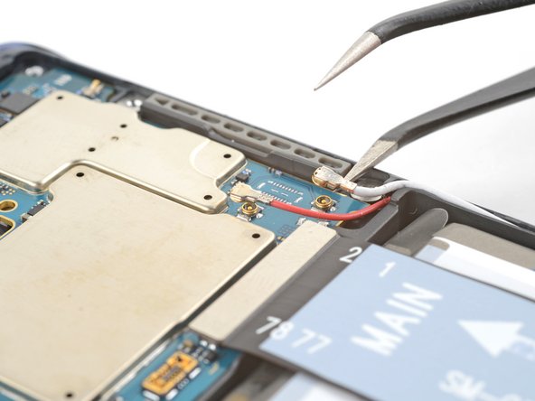

Step 23

– Let’s shake it up a bit, buddy! Wiggle the blue antenna cable loose from its cozy corner at the bottom left of the motherboard, then hand in the HDMI. Keep up the great work!
Step 24
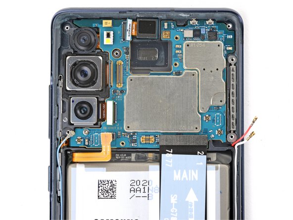

– Grab your trusty Phillips screwdriver and say goodbye to that 4 mm-long screw keeping the motherboard in place.
Step 25

Be sure to check that the SIM tray is out before you pull the motherboard out. It’s a little step that makes a big difference!
– Alrighty, so, let’s get that motherboard lifted up with the spudger’s flat end! Once you can get a grip on it with your fingers, amazing job! Next, carefully remove that bad boy. When you’re all set to put it back together, here’s a pro tip: schedule a repair!
Tools Used
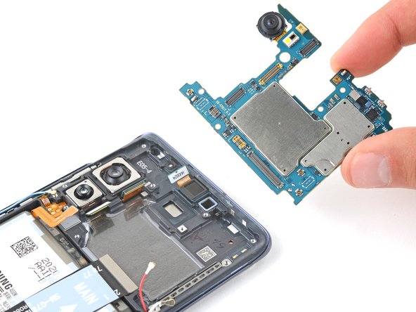
Step 26

– Gently flip the motherboard over and place it on a clean, soft cloth to keep it safe and sound from any damage.

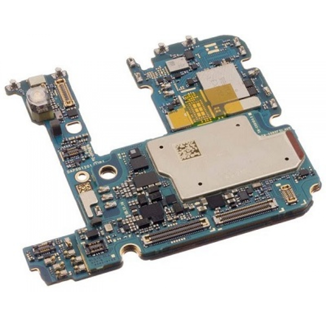
Step 28

– Congratulations, you’ve made it to the motherboard!