Samsung Galaxy S10e Motherboard Replacement Tutorial: Step-by-Step Guide
Duration: 45 minutes
Steps: 36 Steps
Heads up! Make sure you’re working in a cozy, well-lit space. A little organization goes a long way in keeping your repair journey smooth sailing. And remember, if you hit a snag, you can always schedule a repair for extra support!
Ready to tackle the adventure of replacing your Samsung Galaxy S10e’s motherboard? This guide will walk you through the steps to get that pesky motherboard out and a shiny new one in. Let’s dive in and get your phone back in action! If you need help, you can always schedule a repair.
Step 1


– Grab your trusty SIM card eject tool, a bit, or even a straightened paperclip and slide it into that tiny hole in the SIM card tray.
– Give it a firm little push to pop that tray out!
Tools Used

Step 2


– Gently pull the tray straight out to release it. You’re almost there!
Step 3

– First things first, let’s power down your phone completely before diving into this repair adventure. Safety first!
– Now, grab your trusty iOpener and warm up the back of the phone along the right edge for about two minutes. This little trick will help soften the adhesive that’s holding the back cover in place. You’re doing great!
Tools Used

Step 4


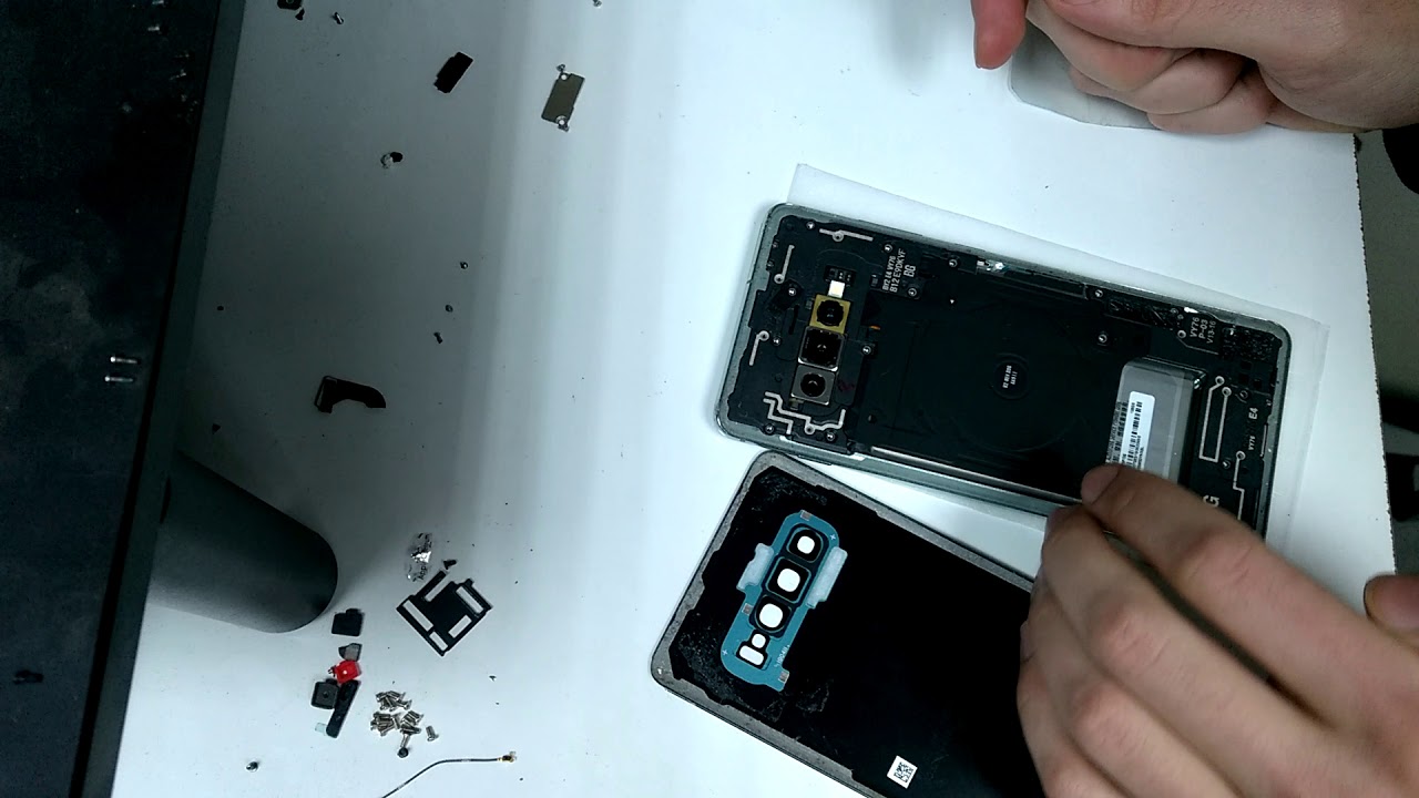
– In the next steps, we’ll be peeling back the adhesive that’s holding the back cover in place. Let’s get that cover off with style!
Let’s take a peek at this image – bam! Right there on the inside after you’ve detached that cover, and voilà, you’ll see heaps of adhesive laid out for your viewing pleasure. If you’re feeling a bit lost, no worries, this is a totally chill process. Just follow along and keep that positive vibe going. If you need some backup, schedule a repair – we’re here to help!
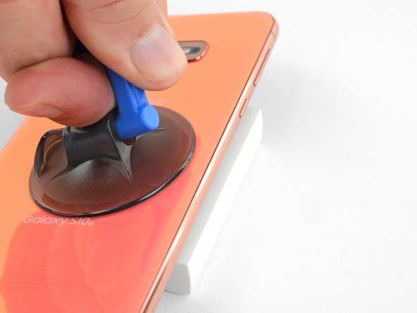
Step 5


– Attach a suction cup to the back cover, aiming for the heated edge right beneath the Bixby button, where the adhesive is at its weakest. You’re doing great, keep it up!
Step 6

Handle that rear glass with care! Too much muscle or using metal tools can lead to a shatter party you definitely don’t want to host.
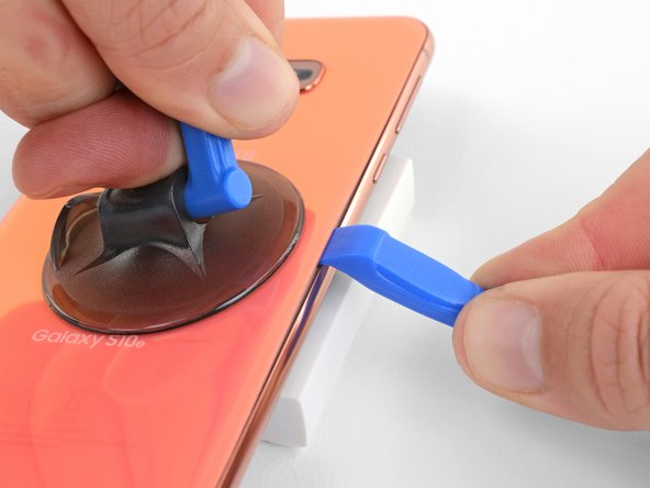
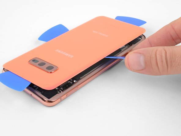
– Kick things off by propping up the heated edge of your phone on something about 0.5 inches (13 mm) thick. This nifty angle will make it a breeze to slip in that opening tool.
– Grab your suction cup and gently lift the right edge of the back cover, creating a tiny gap between the cover and the frame. Easy peasy!
– Now, slide the edge of your opening tool into that gap. You’re doing great!
Step 7


– Gently glide the opening tool down the right side of the phone to break through the adhesive holding the back cover in place.
Step 8


– Woo-hoo! Time to channel your inner superhero and start peeling away that adhesive with a strut that makes us all proud. Don’t forget, it’s a dance and we’ve got your back schedule a repair if you sweat it!

Step 10


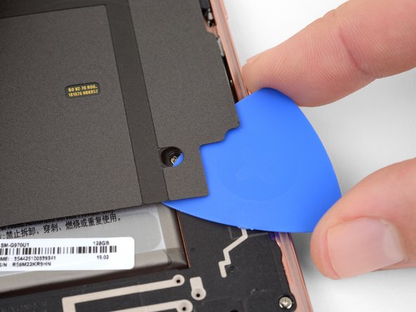
– Grab an opening pick and gently place it near the top right corner of the device. Slowly glide it around the corner and along the top edge.
– Keep the opening pick in position to make sure the sticky stuff doesn’t stick again.
Step 11

– Warm up the left edge of your phone by applying a heated iOpener for two minutes. You’ve got this!
Tools Used
Step 12


– Grab a new opening pick and gently slide it into the top left corner, making your way down the left edge of the phone like a pro.
– Keep that opening pick right where it is along the left edge to stop the adhesive from deciding to play hide and seek again.
Step 13

– Warm up your iOpener and place it on the bottom edge of the phone for a cozy two minutes.
Tools Used
Step 14


– Gently slide an opening pick into one of the bottom corners of your phone, then glide it along the bottom edge to break that pesky adhesive seal. You’ve got this!
Step 15


– Whoa, let’s get this party started! Gently slide a credit card or something similar between the back cover and the phone body. Peeling away the sticker will make our job t-e-a-s-y peasy! Now remove that back cover, and let’s show off our handy work.
– Remember, we’re on a mission. If you get stuck, you can always schedule a repair.
Step 16

Feeling crafty? You can totally pop the back cover back on without needing to swap out the adhesive! Just make sure to clear away any pesky chunks of adhesive that might keep the cover from sitting pretty. Once you’ve got it all set, give it a little heat and press down firm to help it stick! While it might not be 100% waterproof, that leftover adhesive is usually more than capable of keeping things together.
– Get ready to put that back cover on and swap out the adhesive like a pro! You’ve got this!
Step 17

– Get ready to rock by removing the eight 3.9 mm Phillips screws that are holding the upper midframe in place on your phone.
Step 18

– Gently slip an opening pick under the lower right corner of the upper midframe. Ease it in to loosen the sticky bond with the lower midframe.
Step 19


– Gently slide the tip of a spudger into the tiny notch on the right side of the plastic section of the upper midframe, right by the Bixby button. You’ve got this!
– Now, use that spudger to carefully lift the midframe away from the phone’s chassis. Just a little wiggle and it should pop right up!
Tools Used


Step 22

– Grab your trusty Phillips driver and unscrew the seven 3.9 mm screws that are keeping the loudspeaker in place. You’ve got this!


Step 24


– Gently lift the loudspeaker out and set it aside for a moment.
– When it’s time to put things back together, just press on the edges of the loudspeaker until you hear that satisfying snap. You’re almost there!
Step 25

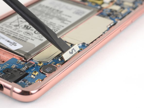
To properly reattach the press connectors, align them carefully by gently pressing down on one side until you hear a satisfying click. Repeat this process on the opposite side. Remember, avoid pressing on the center to prevent any mishaps. If the connectors seem out of place, adjusting them is crucial to avoid any potential damage to the device.
– Gently slide the flat end of a spudger in there and give it a little wiggle to pop that screen connector free from its cozy home on the motherboard. You’ve got this!
Tools Used
Step 26

Hey there, tech-savvy friend! Keep those tiny parts in place while disconnecting those connectors – they’ve got a big job ahead of them in holding everything together!
– Get your spudger ready to gently pry up and disconnect the front facing camera connector from its motherboard socket.
Tools Used
Step 27

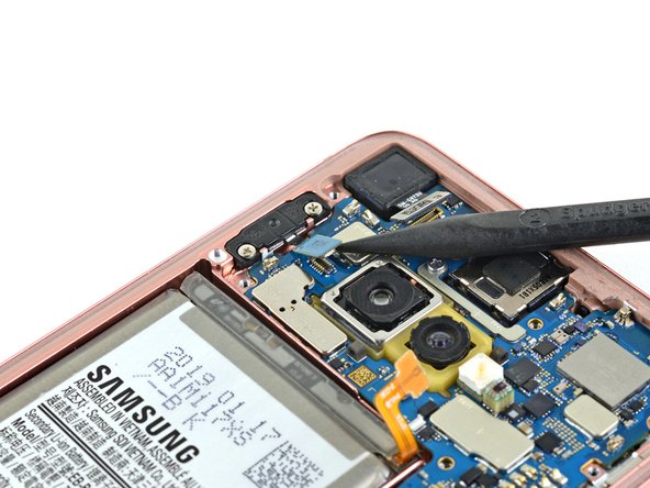
– Gently use the tip of your trusty spudger to lift and disconnect the fingerprint sensor connector from its cozy spot on the motherboard. You’ve got this!
Tools Used
Step 28

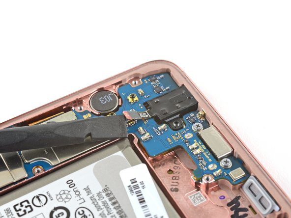
– Grab your trusty spudger and gently pry up to disconnect the headphone jack connector from its cozy spot on the motherboard. You got this!
Tools Used
Step 29

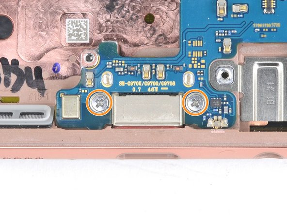
– Grab your trusty Phillips driver and let’s unscrew those three little screws holding the motherboard in place!
Step 30


Before you get too carried away, if the motherboard isn’t moving, take a moment to double-check that the SIM/Micro SD tray has been ejected. Let’s keep things smooth and steady!
– Alrighty, tech buddies! Time to break out the spudger and gently nudge open the top portion of the motherboard. Let’s make this happen and bring that tech back to life! If you need help, you can always check out our repair services.schedule a repair
Tools Used
Step 31

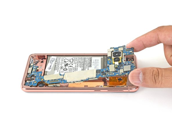

– Time to get your fingers in on the action! Gently lift the top edge of the motherboard out of its cozy frame.
– Now, with a gentle touch, pull the motherboard towards the top of the frame to free the USB-C port that’s just hanging on lightly.
– Go ahead and remove the motherboard like a pro.
– Ready for the grand return? To reinstall the motherboard:
Step 32

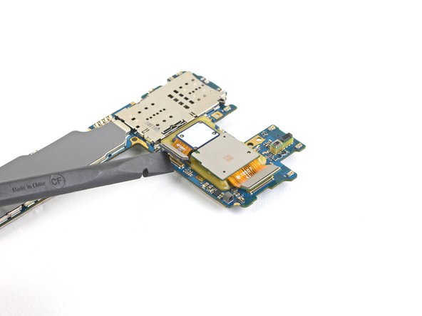
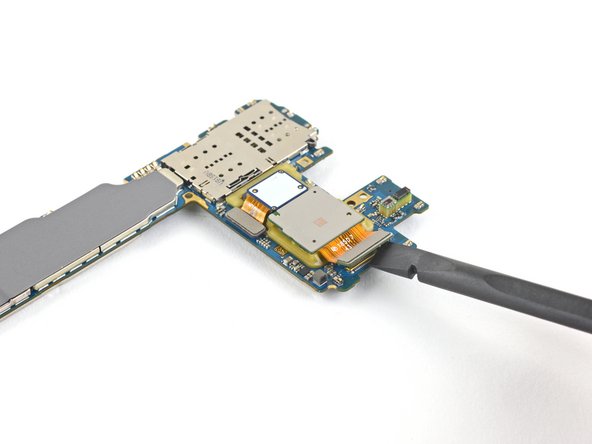
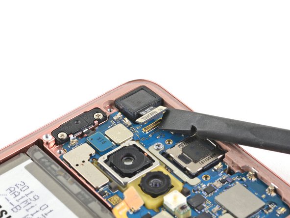
– Now let’s flip the motherboard over with a little flair!
– Time to bust out your trusty spudger and delicately but firmly free the two camera connectors from their snug motherboard sockets.
Tools Used

Step 34

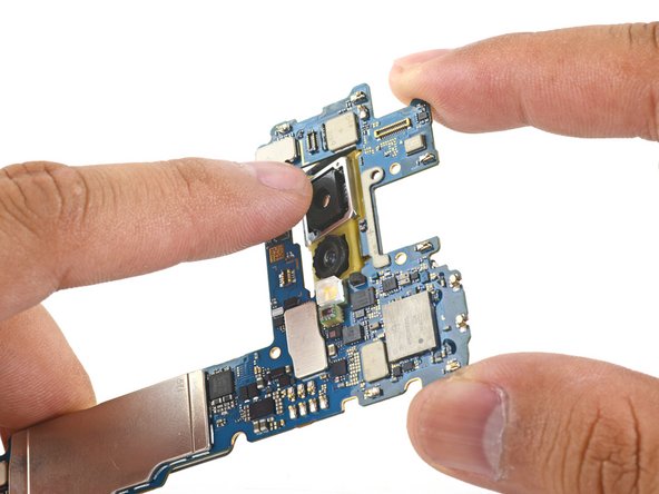
– Give that camera module a little love tap! Use your finger to apply some steady, firm pressure to help it break free from the motherboard. You’ve got this!
Step 35

– Say goodbye to the dual rear camera module. It’s time to gently remove it and make way for the magic to happen!
Step 36

– You’ve made it this far, and now only the motherboard is left in the mix! Take a moment to compare your shiny new replacement part with the original. If you spot any components that need to be moved over, or if there’s any sticky adhesive holding things back on the new part, don’t hesitate to tackle that before diving into the installation!