Samsung Galaxy S10 Display Assembly Replacement Tutorial
Duration: 45 minutes
Steps: 11 Steps
Welcome to our Samsung Galaxy S10 display assembly replacement guide! Ready to dive into some tech magic? Let’s get that device back in action! Follow these steps, and you’ll be on your way to a smooth repair journey. Remember, if you hit a snag, don’t hesitate to schedule a repair for some expert help!
Step 1

– Power down your device and slide out that SIM tray before you get started. If you need help, you can always schedule a repair.
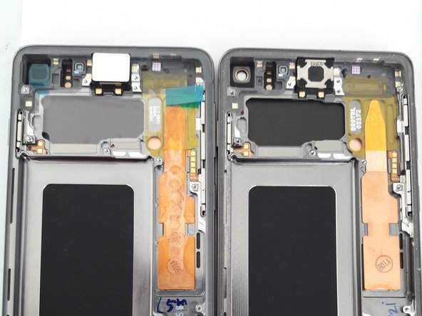
Step 2


– Use a heat gun to warm up the battery cover.
– Grab a suction cup and a pick to gently pry between the back cover and frame. Be careful—the back cover is glass and can shatter easily.
– As you loosen the back cover, leave picks at different points to keep it from re-adhering to the frame.
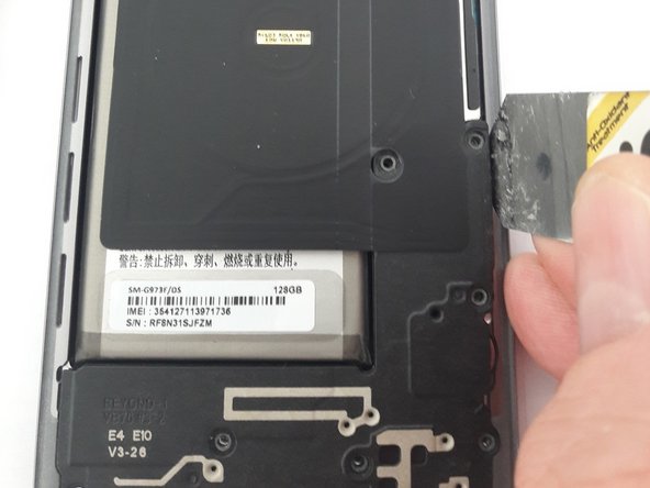
Step 3

– First up, let’s tackle those screws holding down the Antenne Panel cover and the NFC Wireless Charging on the top half of your phone. Unscrew them with care!
– Now, shift your focus to the bottom half of the phone and remove the screws from the loudspeaker cover. You’ve got this!
Step 4

– Gently work a thin metal spudger between the cover and frame to pop off the upper part of the plastic cover.
– Be cautious while inserting the tool between the frame and back cover, as the mainboard is just beneath. If you need help, you can always schedule a repair
Step 5

– With a gentle touch, take a thin metal spudger and pry lightly around the bottom half of the cover. No need to rush; it’s all about finesse!
– Once you’ve got it loosened up, it should come off in one smooth piece. Easy peasy!
Step 6

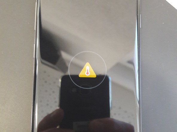
– Hey there! Just a quick heads-up: once you’ve swapped out that screen, it’s a smart move to give the display a test run before putting everything back together. Trust us, it’s worth it!
– And remember, if you skip reattaching the antenna and loudspeaker cover for the test, you might see an error pop up when you plug in the charging cable. So, let’s keep things smooth and avoid any surprises!
Step 7
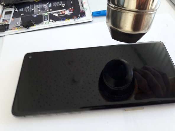

– First things first, let’s disconnect that battery from the mainboard using a trusty plastic tool. Safety first, right?
– Next up, grab your heat gun and warm up the front of the display where the battery is hanging out. A little heat goes a long way!
– Once the glue is feeling nice and toasty, take a thin plastic spudger and gently pry the battery loose. It’s best to start from the frame side for a smoother lift.
– Just a friendly reminder: be gentle! Avoid prying too hard or using anything sharp to remove the battery. We want to keep everything in one piece!
Step 8

– Let’s rock and roll with our trusty plastic spudger and gently release the display cable from the mainboard
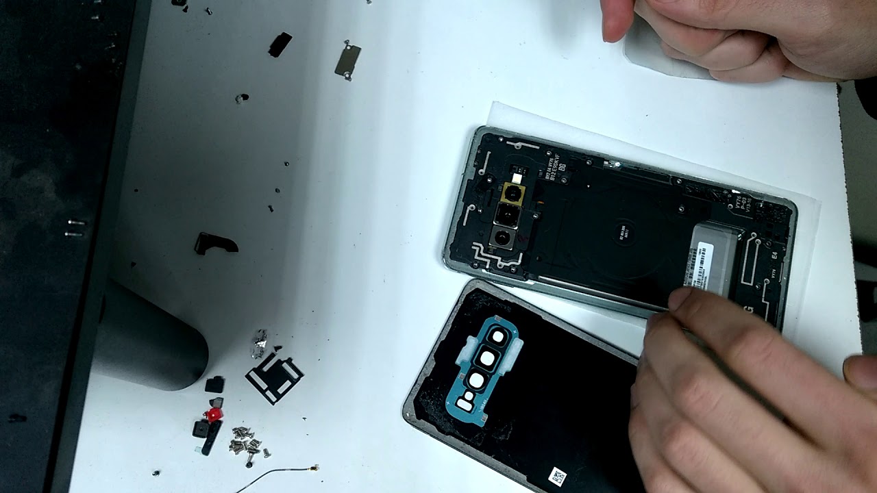
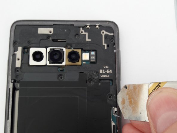
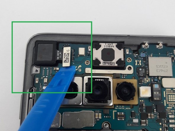
– Time to work some magic with that plastic spudger again and release the camera from the mainboard
– Say cheese to the camera as we remove it and lay it gently to the side
Step 9

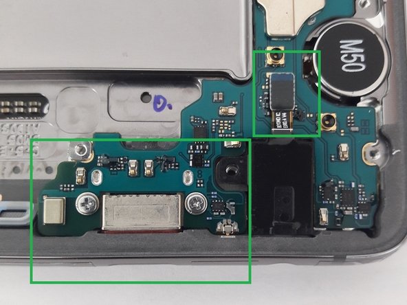
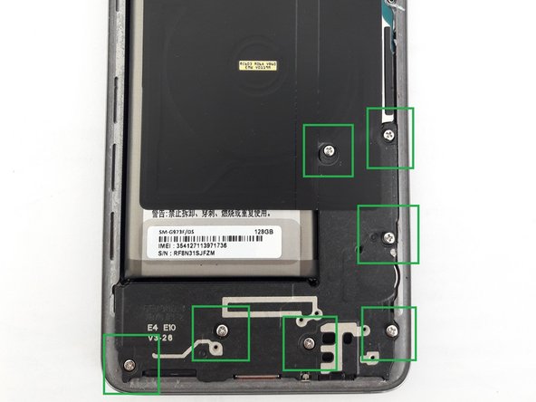
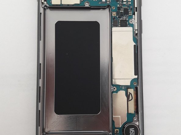
– Let’s kick things off by unscrewing the retaining screw located on the upper half of the mainboard. Easy peasy!
– Next up, grab your trusty screwdriver and remove those two screws on the lower half of the mainboard, right on either side of the charger port. You’re doing great!
– Now it’s time to disconnect the headphone jack connector from the mainboard. Feel free to pull the headphone jack out now or wait until you’ve tackled the mainboard. You’ve got this!
Step 10

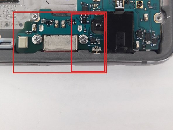
– Grab a pick or a sleek plastic spudger and gently wiggle your way to releasing the mainboard from the top of the frame. Just a friendly reminder: there are two metal connectors hanging out that are a bit delicate, so let’s keep them safe and sound.
– Now, use that trusty spudger to nudge the right side of the mainboard up a bit. It’s like giving it a little lift!
– Heads up! There’s a tiny metal connector on the bottom that needs some extra love—it’s a bit fragile and could bend easily (check out the smaller red box for a visual). So, be super careful when you’re putting the mainboard back in place.
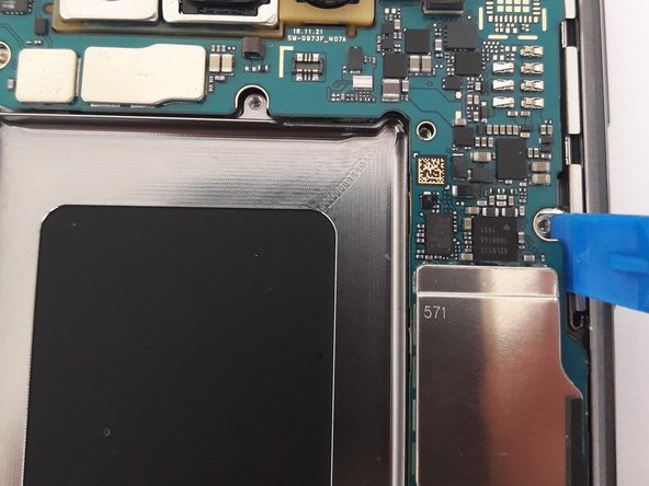
– Once the top of the mainboard is free, you can gently slide it up to coax the charger port out of the frame. (Sorry, no picture of this part, but you’ve got this!)
Step 11

– Sometimes, the vibration motor and speaker might need to hitch a ride to the new display. No worries, the display I swapped had both the vibration motor and speaker all set up and ready to go!
– After you’ve successfully removed the mainboard, grab that trusty heat gun and warm up the bottom of the vibration motor from the screen side. Use a thin, flat tool to gently pry the vibration motor loose—just like unwrapping a present!
– Now, it’s time to put everything back together—just follow these steps in reverse, and you’ll be all set!
– Oh, and don’t forget from step 6: to give your device a proper test run, make sure to attach the antenna/loudspeaker cover. Otherwise, you might see an error symbol on the screen, and we don’t want that!