Nintendo Virtual Boy Teardown
Duration: 45 minutes
Steps: 16 Steps
We’re wrapping up our week of game console teardowns with a true classic: the Virtual Boy. This quirky console stands out as one of the most unique devices we’ve ever opened up. Nintendo described it as a ’32-bit, 3-D experience’ designed to fully immerse you in a personal gaming universe. Despite its bold claims, the Virtual Boy has had its share of critics, even landing on lists of the worst and weirdest tech creations. But hey, those lists didn’t get inside to see what makes this machine tick. Ready to find out what’s really going on under the hood? Let’s dig into the Virtual Boy and uncover the secrets behind its short but unforgettable run.
Step 1


– The Virtual Boy made a quick cameo in North America—just seven months on the scene, from August 14, 1995 to March 2, 1996. Only 770,000 units ever found a home, which is tiny compared to the Nintendo 64’s whopping 32.93 million.
– Tech Specs:
– 20 MHz, 32-bit RISC Processor
– 128 KB dual-port VRAM
– 384 x 224 pixel resolution
– 2-bit monochrome display (black and three shades of red)
– 16-bit stereo sound
Step 2


– The Virtual Boy might not quite make the cut for the worst-looking piece of tech ever, but it definitely gives off some vibes of iconic sci-fi characters.
– The Neoprene eyepiece covers the entire field of vision, which not only puts you in your own little world, but also keeps the outside world from peeking into your game time.
– Games like Mario’s Tennis take advantage of the Extension port located underneath the Virtual Boy. Unfortunately, Nintendo never released the cable needed to fully utilize it.
– Imagine if the Virtual Boy could play ‘other’ kinds of content… now that would have been a game-changer!
Step 3


Snapping that screenshot took some extra patience—Wario just couldn’t sit still!
– The Virtual Boy had a pretty limited lineup, with just 22 games, and only 14 of those made it to North America. Some of the standout titles include Mario’s Tennis, Wario Land, 3D Tetris, and Teleroboxer. To create a convincing 3D experience, a special control method was needed to handle movement along the z-axis. This was achieved by adding a second D-pad to the controller. And no, that’s not an infrared image of Wario—Virtual Boy used three shades of red to craft its on-screen visuals. If you need help with any repairs, you can always schedule a repair.
Step 4


After wearing safety glasses and sparks flying from our rotary cutoff wheel, we ended up with a neat little gamebit socket that’s easy to turn with a flathead screwdriver. Sometimes, a little sparks and a bit of grinding can turn into the perfect tool for the job.
– Taking apart the Virtual Boy isn’t exactly a cakewalk, but we’ll get through it together.
– When our 1/4″ drive gamebit didn’t quite fit into some of those tricky recessed screw holes, we had to get a little inventive.
– With those obstacles out of the way, we’re ready to start disassembling this device step by step.
Step 5


Nintendo seems to have thought ahead when designing the tripod base – it’s easy to remove, just in case it decides to take a tumble and break during a fall. Smart move, right?
– The neoprene eye shield and its frame should easily pop off the back of the Virtual Boy.
– Once you’ve taken care of the screws holding the tripod base in place with your custom gamebit, it should lift right off the lower case without a hitch.
Step 6
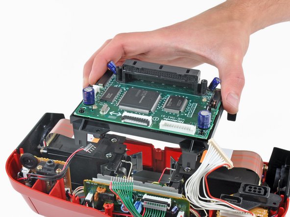
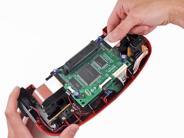

– Once you’ve tackled the tricky screws, it’s time to gently lift off the lower case from the Virtual Boy. It should come off without a hitch!
– You’ll notice a few ribbon cables connecting the main board to the rest of the components. After carefully disconnecting them, the board should slide right out with ease.
Step 7
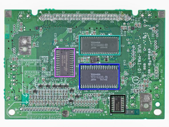

– The main board handles all the heavy lifting—taking signals from the controller, loading game data from the cartridge, sending audio to the speaker amp, and powering the LED displays. You’ll find these chips on the board, including: Nintendo ’95 VUE-VPU (9520KK023), Nintendo NVC-VUE (NEC ’91-’93, 9520KX003), Nintendo VRM-VUE (9508KU028), Toshiba TC511664BJ-80 128 KB DRAM, Toshiba TC511632FL-70, Nintendo ’95 VSU-VUE ATT (9507A3014), and Texas Instruments 57A5CXK, HCU04. When you’re ready to dig in, follow the step-by-step guidance to identify and replace these components. If you need help, you can always schedule a repair.
Step 8

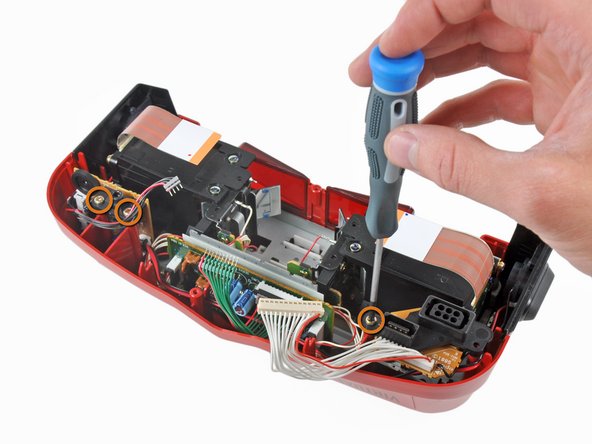

The Virtual Boy’s modular build means it’s made with repairability in mind. If the controller port or audio system gets damaged, you can swap out just that part instead of replacing the whole motherboard. It’s designed to make repairs straightforward and less of a hassle.
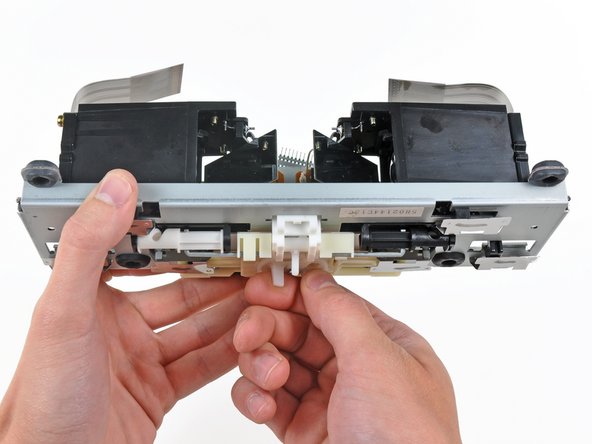
– Use a Phillips screwdriver to remove the screws holding the controller port and sound boards in place on the upper case. Once the screws are out, gently lift both boards away from the Virtual Boy to continue with your repair. If you need help, you can always schedule a repair.
Step 9

The rubber isolators between the metal display assembly chassis and the upper case are there for a reason – they help absorb vibrations from the Virtual Boy’s two oscillating mirrors. They’re the unsung heroes of smooth operation, so don’t underestimate their importance.
– First, carefully detach the controller board and the sound system components. Once those are out of the way, proceed to remove the display assembly. Take your time and handle everything gently. If you need help at any point, you can always schedule a repair to get professional assistance.
Step 10

– Spin the knob on top of your Virtual Boy to adjust the space between the screens – this matches up with the distance between your eyes, bringing the displays closer together or farther apart.
– Slide the focus lever back and forth to fine-tune the lens position inside each display unit. This helps you get that crisp, clear 3D effect.
– The Virtual Boy works its 3D magic using parallax: each eye looks at the scene from a slightly different angle, thanks to the way the displays are set up.
– Your eyes are spaced a few inches apart, so they each send a unique image to your brain. The brain then combines these into a single, depth-filled 3D view. That trick is called stereopsis.
– The Virtual Boy shows a slightly different picture to each eye, letting your brain mix them together and create that awesome stereoscopic 3D effect.
Step 11


– The Virtual Boy gets its signature 3D look with a seriously clever approach to visuals.
– A tiny mirror zips back and forth at lightning speed, while LEDs refresh so quickly your eyes see a seamless, solid image.
– Each display uses a row of LEDs just one pixel tall, shooting light through a lens right in the center.
– After that, the light hits a mirror set at a 45-degree angle, which pivots rapidly to paint the whole image across your field of view.
Step 12

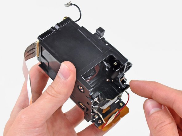
– To get that mirror moving just right, we pass a high-frequency alternating electrical current through a copper coil attached to the mirror. The coil creates a magnetic field that works with a stationary iron core attached to the display unit, turning it into a solenoid and generating the force needed to make the mirror oscillate.
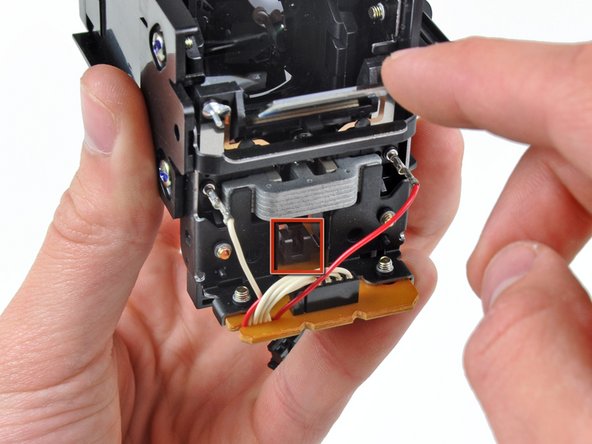
– Now, to keep track of how fast that mirror is swinging, an arm is attached to it. This arm moves back and forth through an optical sensor on the lower circuit board, giving the oscillator the information it needs.
Step 13

– This board is the mastermind behind getting both mirrors to oscillate just right.
– The chips here grab display info from the main board and keep those mirrors moving at the perfect rhythm, thanks to feedback from the optical sensors you saw earlier.
– An 8 MHz crystal, soldered right on the board, handles the timing for the mirror action.
Step 14
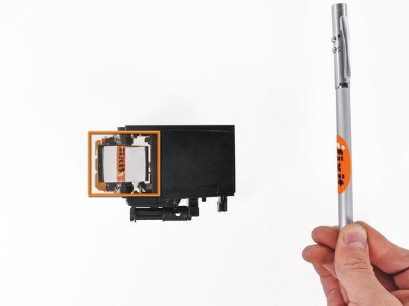

– Grab your trusty T10 Torx screwdriver and remove the two screws holding the LED unit in place at the end of the display assembly.
– Once the LED unit is out, check out the cool ‘periscope’ reflection and the slight magnification effect created by the 45-degree mirror and the internal lens.
Step 15


– Meet the Virtual Boy display! Each display unit rocks a 1×224 pixel layout with 32 shades of brightness, all thanks to some clever engineering by Reflection Technology Inc.
– Every image you see is actually just a single line of red dots. An oscillating mirror sweeps this row to create a complete picture—pretty wild, right?
– With only one row of LEDs handling the whole show, the refresh rate is off the charts. Each LED pattern flashes for a super-quick 0.000052 seconds!
– LCDs were in the running for the display, but they just couldn’t keep up—blurry city! LEDs won out because they’re speedy and give off a nice, bright, steady glow.
– The team thought about using more colors but had to stick with red—those LEDs were the most affordable, efficient, and visible. Sometimes the classics just win out!
Step 16

– What a fantastic way to wrap up a week of retro gaming! We’ve journeyed through the Magnavox Odyssey 100, RCA Studio II, Atari 2600, Famicom, and now, the Virtual Boy. We hope you had as much fun as we did!
– Quick heads-up: We’ve just launched a brand new store for game console parts to help keep your (slightly newer) consoles running in top shape!
Success!