How to Replace Samsung Galaxy S8 I/O Daughterboard – Step-by-Step Tutorial
Duration: 45 minutes
Steps: 34 Steps
Before diving into fixing your device, make sure you drop that battery level below 25%. If you accidentally poke it, things could get a little hot! Trust us, letting it chill out a bit beforehand can save the day.
Get ready to swap out the I/O daughterboard in your Samsung Galaxy S8! If your USB-C connector or microphone is acting up, it’s time for a change. We’ll guide you through the process of removing the rear glass cover, but don’t forget to grab some replacement adhesive to seal it back up nicely afterward. Keep in mind that the motherboard and daughterboard vary a bit depending on whether you own the North American Snapdragon (G950U) or the international Exynos (G950F) version of the phone, and this guide focuses on the North American model. Just a heads up: those two versions aren’t interchangeable. Before you dive in, remember to discharge the battery to below 25%. A punctured battery can be a bit of a fire hazard, but the risk is much lower when it’s not fully charged. Happy repairing!
Step 1


We suggest giving your microwave a good clean before diving in, as any leftover gunk on the bottom could end up sticking to the iOpener. Let’s keep things tidy!
– Pop the iOpener right in the middle of the microwave like it’s the star of the show.
Tools Used

Step 2

Hey there! Just a friendly reminder to keep an eye on that iOpener during your repair adventure. Letting it get too hot can lead to a pop! So, let’s keep it below 100˚C (212˚F), shall we?
If you see any signs of swelling, steer clear of the iOpener! Safety first!
Still feeling a bit too hot to handle? No worries! Just hang tight and let it cool down a bit before you reheat. A properly warmed iOpener should keep you cozy for about 10 minutes.
– Give that iOpener a warm-up session for thirty seconds. It’s like a cozy blanket for your device!
– As you dive into the repair process, keep an eye on your iOpener. When it starts to chill, pop it back in the microwave for another thirty seconds to keep the heat flowing.
Tools Used
Step 3

The iOpener is going to be super hot, so handle it with care! Feel free to rock an oven mitt if you need to.
– Take the iOpener out of the microwave, gripping one of the flat ends to steer clear of the hot center. Keep it cool while you get ready for your repair adventure!
Tools Used
Step 4
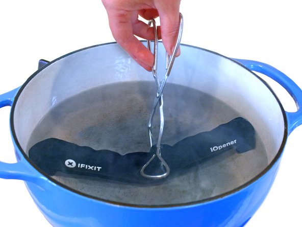

No microwave? No problem! Just follow this quick tip to warm up your iOpener using boiling water.
– Grab a pot or pan and fill it with enough water to totally dunk that iOpener in there!
– Get that water boiling hot and then turn off the heat—you’re almost there!
– Carefully drop the iOpener into the warm embrace of the hot water for 2-3 minutes. Just make sure it’s fully submerged; we want it cozy!
– Use some tongs to fish out the nice and toasty iOpener from the hot water—safety first!
– Give the iOpener a good dry-off with a towel, because nobody likes a soggy iOpener.
– And voilà! Your iOpener is all set for action! If it needs a little more heat, just repeat the process—boil the water, turn off the heat, and let it soak for another 2-3 minutes.
Tools Used
Step 5

Don’t sweat it! You’ve got options. Grab a hair dryer, heat gun, or hot plate for the job. Just remember to play it cool and not overheat your device. The OLED display and battery are sensitive to heat, so keep it chill while you work your magic.
Remember, popping open your phone might break its waterproof magic. Make sure you’ve got fresh adhesive on standby or take it easy around liquids if you’re sealing it back up without fresh adhesive.
While your adhesive is softening up, why not check out the next step and see where to work your magic.
– Hey there! Let’s get that edge nice and warm by applying our trusty iOpener for about 2 minutes. Feeling the heat together is so much fun, right? Keep up the awesome work!
Tools Used
Step 6


– Get ready to tackle that adhesive like a pro! You’re going to expertly slice through the sticky stuff lining the edge of the rear glass panel.
– Take a peek at the first image to see how the adhesive on the rear case is arranged.
– Check out the prying pattern that you’ll be following from the outside of the phone – it’s all laid out for you right here:
Step 7


– When the back panel feels warm and cozy, grab a suction cup and place it near the warm edge of the phone—just steer clear of that curved part.
– Give the suction cup a gentle lift, then slide an opening pick underneath the rear glass to start your adventure!

Step 9


Take it easy to avoid any slip-ups. If you find it tough to cut, just warm up the iOpener and give it another go.
– Gently slide the opening pick down the side of your phone to peel away that sticky adhesive like a pro!
Tools Used
Step 10


– Now, let’s keep the momentum going! Just like before, heat things up and carefully cut around the next three sides of the phone. You’re doing great!
– As you work your magic, remember to leave an opening pick on each side. This little trick will keep the adhesive from sticking back together. Keep it up!
Step 11


As you gently lift the glass, take a quick peek to ensure that the orange cable with the blue connector has come loose. Keep an eye out for it!
If the fingerprint sensor cable looks like it’s stuck or too tight, hold up there! Don’t force it open any further. Use the tip of a spudger to disconnect the connector before moving on.
The fingerprint sensor cable is like a little bridge connecting your phone to the rear glass near the main camera. It’s a short one, so when you gently lift off that rear glass, the cable will happily disconnect itself. No need to worry about it getting in the way!
– Let’s kick things off by using the opening picks to slice through any remaining adhesive and give your phone a gentle opening.
– Now, as you put things back together, to reconnect the fingerprint sensor cable, start by angling the back cover just right until the cable connector lines up perfectly with its socket. Next, take the flat end of your spudger and gently snap the connector into place by pressing it down directly.
– Go ahead and remove the glass from your phone.
Tools Used

Step 12

Feel free to pop that back cover back on without fussing over new adhesive! Just make sure to clear away any stubborn adhesive blobs that might stop it from sitting nice and snug. Once it’s in place, give it a little warmth and some gentle pressure to lock it down. While it might not be fully waterproof, the old glue usually does a great job of keeping everything together.
– Ready to give your device a fresh look with a new back cover? Let’s get started!
– Check out this guide to switch out that old back cover or to put on a new one that doesn’t come with its own sticky stuff.
– Oh, and if you’re transferring the camera bezel to your new cover, no worries! Just hop on over to our camera bezel replacement guide for some handy tips.
Step 13

– Using a Phillips #000 screwdriver, carefully take out eleven 3.7 mm screws. You’ve got this!
Tools Used

Step 14


– Take a moment to carefully detach the NFC antenna and charging coil assembly. You’ve got this!
Step 15

– Time to bid farewell to three 3.7 mm Phillips #000 screws!
Step 16

– Let’s jazz things up a bit by getting that loudspeaker assembly out of there!
Step 17


– Grab your trusty SIM card ejector tool and slide it into the tiny hole on the left side at the top edge of your phone.
– Give it a gentle press to pop that tray out!
– Carefully pull the SIM card tray out of the phone and voilà!


Step 22


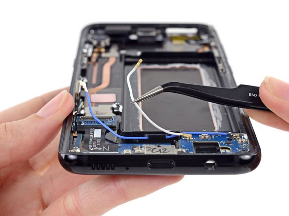
– Grab your trusty spudger and gently pry apart the two antenna cables linking the motherboard to the daughterboard. You’ve got this!
Tools Used
Step 23


– Grab that trusty spudger and gently use its flat end to disconnect the antenna ribbon cable linking the motherboard to the daughterboard. You’re one step closer to getting everything back in working order!
Tools Used
Step 24

– To work magic on your device, gently use the flat end of a spudger to give the motherboard a lift and disconnect it from the daughterboard.
Tools Used


Step 26

– Time to say goodbye to one tiny 3 mm Phillips #000 screw. Let’s bid it a fond farewell!
Step 27


– Grab your trusty spudger and gently pry away the headphone jack connector. You’re almost there!
Tools Used
Step 28


– Get your spudger ready and aim for the sweet spot between the headphone jack and the board, right by the corner of the jack where it meets the ribbon cable.
– Time to show that headphone jack who’s boss! Gently nudge it out of its cozy spot using your trusty spudger.
– Give that headphone jack a break – remove it like a pro.
Tools Used


Step 31

– Let’s give these screws a workout! Unleash your inner handyman and give these 5 pesky 3 mm Phillips #000 screws a run for their money. If you need help, you can always schedule a repair.
Step 32


– Carefully bend the motherboard connector downwards and tuck it away from the antenna ribbon cable, making sure it’s out of the way like a pro.
Step 33


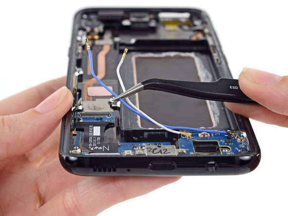
– Carefully use your tweezers to lift the antenna ribbon cable off the side of the case. You’ve got this!
Tools Used


