How to Replace Samsung Galaxy S4 Active Display Tutorial
Duration: 45 minutes
Steps: 20 Steps
Heads up, tech warrior! Make sure you’ve got your tools ready and your workspace clear. Let’s make this gadget feel brand new again!
While swapping out the rear camera on my S4 Active, I ended up cracking the mid-frame—yep, that definitely compromises water resistance! Turns out, a solid disassembly guide for the Samsung Galaxy S4 Active was hard to find, which led to some unintended DIY drama. I’ve ordered new parts, and as they’re on their way, I thought, why not create this guide? It’s here to ensure your phone stays safe and sound during your repair adventures!
Step 1


– First things first, if your device is rocking a micro SD card, give it a proper send-off by unmounting it.
– Next up, let’s power down your device and pop open the back casing like a pro.
– Now for the fun part: yank out that battery, eject the SIM card, and liberate your microSD.
Step 2


– First things first, let’s tackle those 12 screws holding the mid frame in place. But before you dive in, you’ll want to pop off the 4 metal circles from the corners of your device. Trust me, it’s a must!
– I’ve discovered that a sewing needle is a handy little tool for getting just about everything out, except for those pesky screws in your phone. It’s like having a secret weapon in your repair arsenal!
– Once you’ve removed those 4 metal circles, I like to stick them to my battery. It’s a clever way to keep them safe and sound, so they don’t go wandering off!
Step 3

– Remove the 12 midframe screws and pop them into a container to keep them safe—those little escape artists love to vanish on the floor!
Step 4

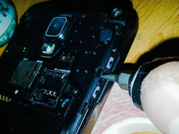
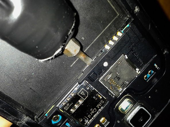
Heads up! When you’re removing the midframe, watch out for those sneaky hidden security clips. I learned the hard way when my midframe snapped—don’t let it happen to you!
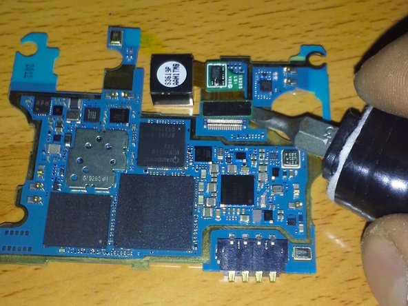
– Right near your volume button, tucked between it and the midframe, is a sneaky little clip. Take a flathead screwdriver or a slim blade, and gently coax it into that narrow space to persuade the clip to loosen up.
– Looking for another clip? It’s hiding right between the SIM slot and the 4 prong battery terminal. Spot the small gap at the bottom? Give it a gentle pry to pop that clip out of its hideout.
Step 5

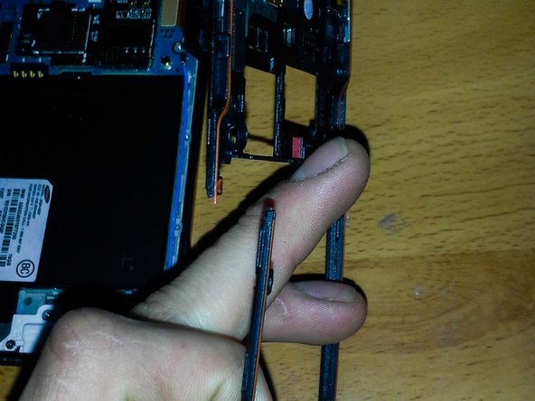
Oops! This is what happens when those sneaky security clips aren’t unhitched.
– As you remove the midframe, you might notice the charging cover making a sneaky escape from the phone. No worries, it’ll snap right back into place when we put everything back together.
– With the main frame now out of the way, there’s just a bit more magic to work on the midframe.
Step 6

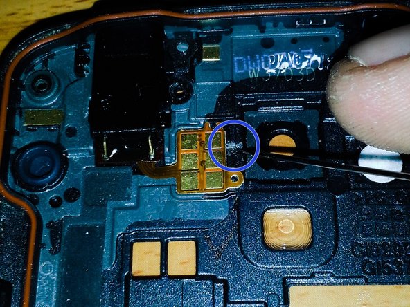

Always treat those flex cables like the delicate treasures they are to prevent any rips or tears.
– Heads up! Unlike the standard Galaxy S4, the headphone jack on the S4 Active is attached to the midframe instead of the mainframe.
– All removable flex cables have a nifty access slot to slip a tool (a sewing needle works wonders) underneath the adhesive and gently lift it up.
– Once you’ve got that flex cable free, you can remove whatever’s attached to it. In this case, it’s the headphone jack.
Step 7
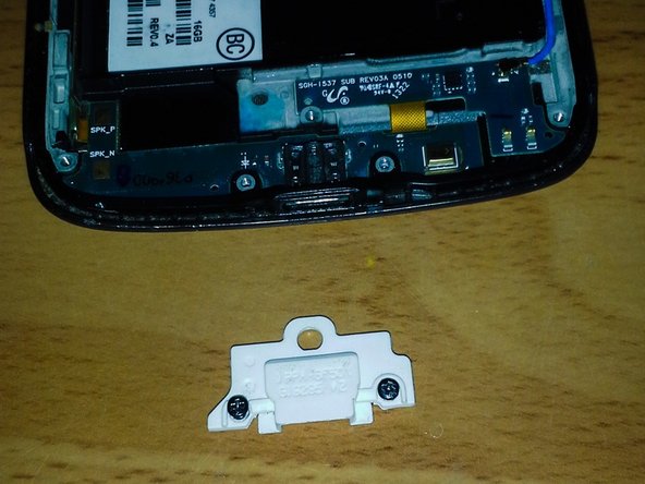


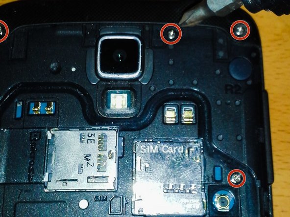
– Let’s get started by removing the two black screws that hold the daughterboard and USB charging dock in place. You’ll find them hiding in the white USB protector – easy peasy!
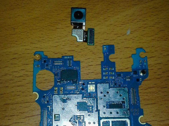
– Now, locate the last screw on your S4 Active, which is conveniently situated at the top of the motherboard, just to the left of the earpiece and rear-facing camera. Almost there!
Step 8

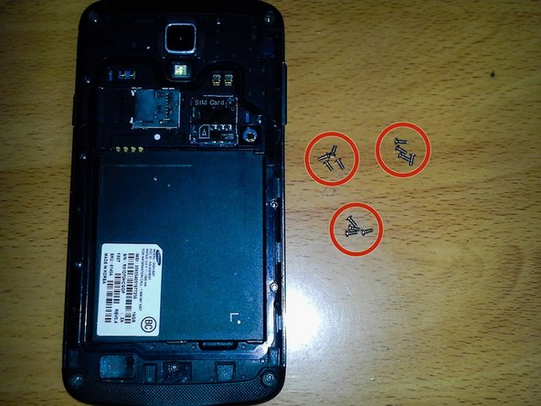
– Alrighty, gear up to unscrew a total of 15 screws. We’ve got 12 shiny stainless Midframe screws and 3 stealthy black board screws.
Step 9

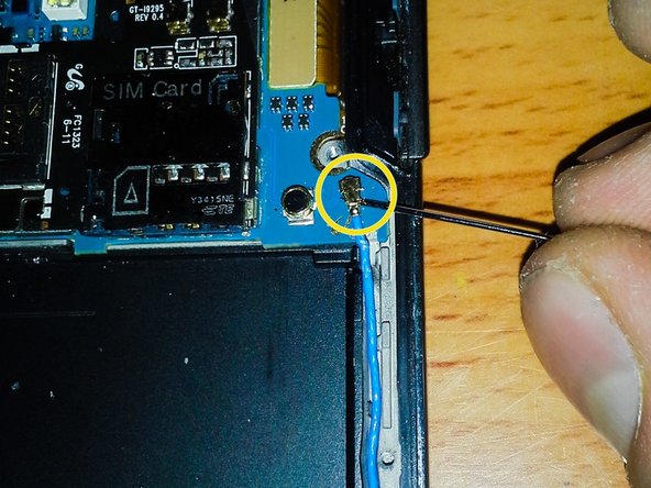
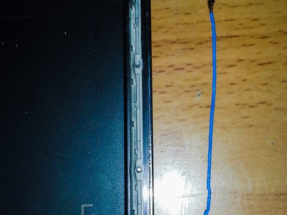
– The antenna stretches its long legs from the motherboard all the way down to the daughterboard.
– Unplug both ends of the antenna and gently place it aside.
Step 10
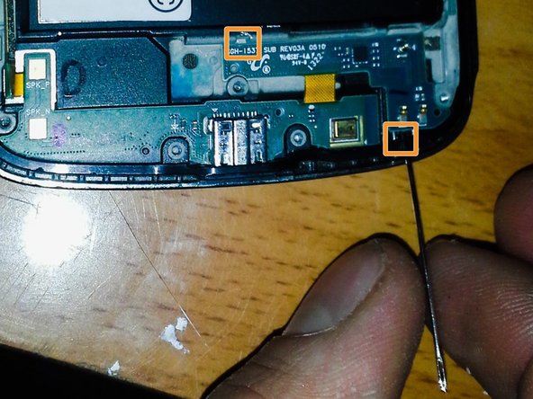

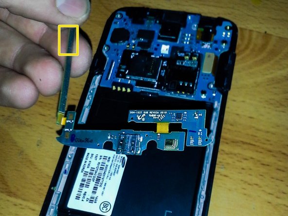
– Carefully disconnect the flex cable connector from the motherboard.
– Locate the two daughterboard access slots and gently remove the daughterboard from the device.
– Take hold of the flex cable and smoothly extract the charging port and daughterboard as a single unit from the device. (They should separate easily without force)
Step 11
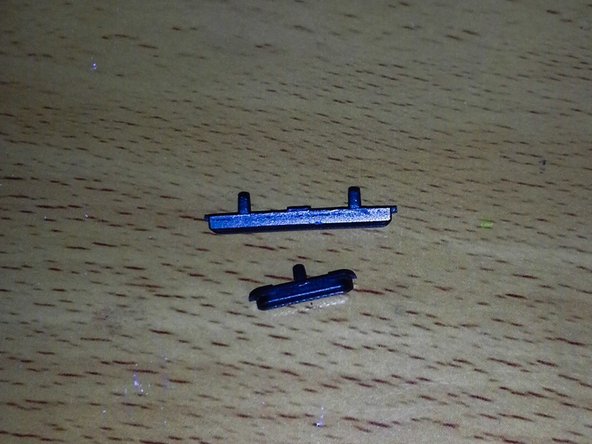


– Popping these buttons out is a breeze, though getting them back in? That’s another story!
– Just slide a pry tool behind the button and give it a gentle nudge. Voila, it’s out!
Step 12


– Unplug all those sneaky cables first.
– Give the SIM/SD Reader a break.
– Separate the Digitizer with care.
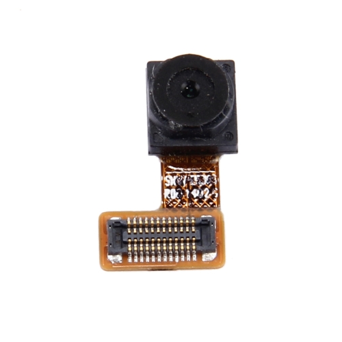
– Unhook the Front Facing Camera.
– Detach the Proximity Sensor gently.
– Ease out the LED Status Light/RGB Sensor Module.
Step 13

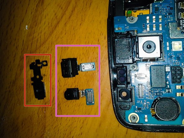
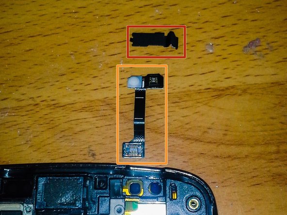
– There’s a sneaky black metal bracket keeping the Front Facing Camera and Proximity Sensor in check. Let’s liberate them!
– Start your liberation mission by prying off the bracket from the right side.
– Now, remove the Proximity Sensor and Front Facing Camera. Freedom at last!
Step 14

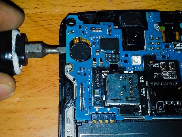
Handle the motherboard by its edges only, like it’s a hot slice of pizza! Avoiding ESD (that sneaky Electrostatic Discharge) is crucial—nobody wants a fried motherboard for dinner!
– One side at a time, carefully coax the motherboard away from the phone, like you’re peeling a banana.
– Make sure you don’t tangle or bump any lingering flex cables with the motherboard as you lift it out. It’s like a game of Operation!
Step 15


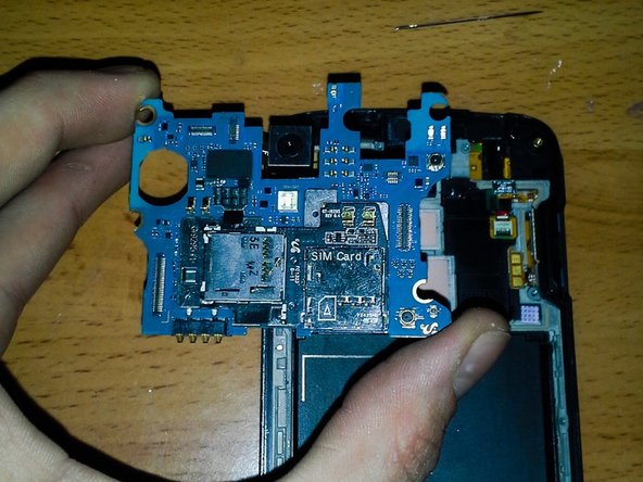
Hey there! Only take this off if you’re planning to put it back on. It’s not too fond of coming off or going back on easily.
– Looks like your SIM Reader is on the fritz, but fear not! Since it’s connected to the Micro-SD, we’ll need to swap out the entire unit to get things back in ship shape.
Step 16

Pop the motherboard into a cozy spot on the side where it can chill until you’re ready to bring your phone back to life!
– Flip that motherboard like a pancake and unplug the flex cable connector like a boss!
Step 17

– This component is also secured by a bracket, so just pop it off the same way you did with the last one. You’ve got this!
– Next up, it’s time to take out the LED Status Light/RGB Sensor. Let’s keep going!
Step 18


My Earpiece Speaker is kaput. Time to hit up eBay!
– Here’s a heads-up: flex cables are super delicate, so let’s handle them with care.
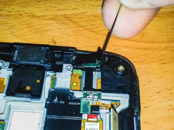
– Pro tip: Grab a couple of prying tools to tackle your Earpiece flex cable. That adhesive is like super glue! (Check out the orange highlights to see exactly where the flex needs to be freed up.)
Step 19
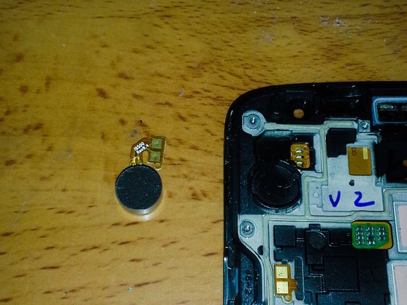
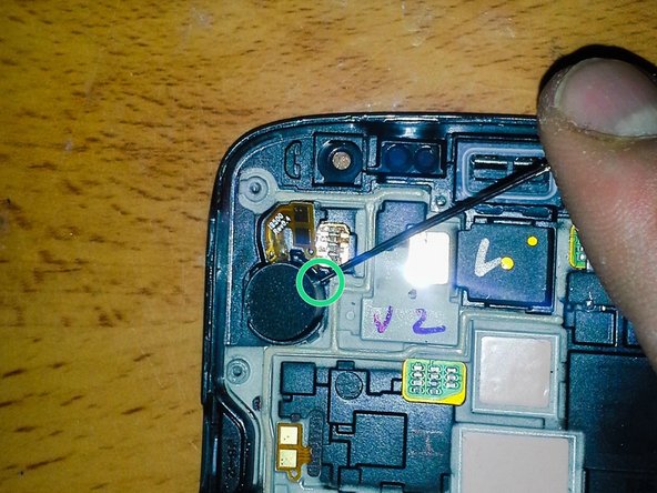

– Spot the sneaky access slot right under the flex cable and the buzzing vibrator. Watch out, there’s a sticky situation with lots of adhesive under the vibrator!
– Time to part ways with the vibrator.
Step 20

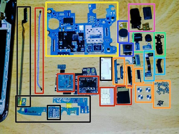
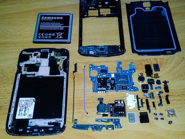
– Let’s dive into the tech pool! Start with the Daughterboard, USB Port, USB Protector, and those nifty Flex Cable Connectors.
– Next up, tackle the Antenna, SIM, SD Reader, and don’t forget your SIM and Micro-SD cards.
– Moving on, swap out the USB Water Cover, get clicky with the Volume and Power Buttons, and round up all those Screws and misc hardware.
– Motherboard time! Carefully handle the brains of the operation.
– Snap to it with the Front Facing Camera, Proximity Sensor, and secure them with the Bracket.
– Shine a light on the LED Status Light and RGB Sensor Module, securing them with the Bracket.
– Switch gears to the Rear Facing Camera and Vibrator, ensuring everything’s picture-perfect.
– Lastly, don’t miss the Headphone Jack and Earpiece Speaker, wrapping up your tech-savvy adventure.