How to Replace Samsung Galaxy S4 Headphone Jack Assembly DIY Guide
Duration: 45 minutes
Steps: 16 Steps
Heads up! Make sure you’ve got your tools ready and your game face on. We’re diving into this repair together, and it’s going to be epic. If you hit a snag, remember, help is just a click away at schedule a repair. Let’s make this device feel brand new!
Use this guide to replace the headphone jack assembly, including the status light and infrared sensor, in your Samsung Galaxy S4.
Step 1


– Grab a plastic opening tool or just use your fingernail to wiggle into the little notch next to the rear camera, right by the power button. Let’s pop this open!
Step 2


– Grab the rear case near the little notch and whoosh it off the phone like a magician pulling a tablecloth. Voila!
Step 3


– Gently wiggle a plastic opening tool or your finger into the groove of the battery compartment and give the battery a little upward nudge.
– Lift the battery out and wave goodbye as it leaves your phone.
Step 4


– Gently press the SIM card further into its slot using a plastic opening tool or your fingernail until you hear a satisfying click.
– Once you hear that click, let go and the card will spring out of its slot.
– Take out the SIM card.
– When putting it back together, just push the SIM card back into its slot until you hear that reassuring click indicating it’s securely in place.
Step 5

– Unscrew the nine 4.0 mm Phillips #00 screws that are holding the midframe snugly against the display assembly.
Step 6


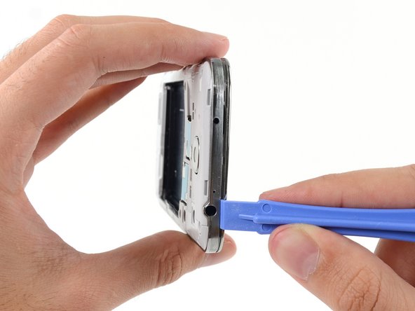
– Begin on the side of the phone with the volume buttons. Place your plastic opening tool between the display glass’s chrome bezel and the larger chrome border. Look for the seam connecting the two components.
– Gently slide the opening tool along the seam. Work your way around, detaching the plastic clips as you proceed.
Take it easy and gently when prying those clips apart! Just nudge them enough to loosen up—like coaxing a cat out from under the bed. Remember, the midframe is as delicate as a house of cards in a breeze. Let’s keep everything in one piece!
The midframe is snugly held in place by a bunch of plastic clips located behind the chrome bezel. Don’t worry, the upcoming steps will show you how to pop those clips like a pro and liberate the midframe!
Step 7


– Keep the groove going around the corner of your phone with your prying tool.
– Wiggle your opener along the bottom seam between the midframe and display, popping those pesky plastic clips free as you go.
Step 8


– Next up, let’s gently wiggle our pry tool around the corner, cruising towards the power button side.
– Keep the party going by gliding the opening tool right along that sneaky seam.
Step 9

Now’s a good time to take your plastic opening tool for another spin around the device’s edge to ensure all those sneaky plastic clips are totally free. Keep at it, you’re doing great!
– Keep cruising with your opening tool along the top edge of your phone. Pop those last pesky clips to liberate the midframe from the display assembly. Almost there, champ!


Step 11


– Pop off the USB board connector with the flat end of a spudger, like a pro!
– Unhook the front-facing camera cable connector. Easy peasy!
– Detach the earpiece speaker assembly cable connector. You’re doing great!
Step 12


– Unplug the headphone jack assembly cable connector. It’s like saying bye to a friend, but don’t worry, you’ll reconnect soon!
– Next up, disconnect the display/digitizer cable connector. Gentle as a feather now!
– Finally, unhook the antenna cable connector. You’re doing great!
Step 13

– Unscrew the single 2.4 mm Phillips #00 screw holding the motherboard assembly. Let’s do this!
Step 14


Grab the motherboard by its edges to avoid any static shocks. As you lift it away from the display assembly, watch out for those sneaky cables trying to catch a ride!
– Carefully coax the motherboard out of its comfy home.
Step 15

– Unscrew the single 2.4 mm Phillips #00 screw that’s holding the headphone jack assembly in place on the display assembly.