DIY MacBook Pro 15 MagSafe DC-In Board Replacement Tutorial
Duration: 45 minutes
Steps: 28 Steps
Don’t worry, we’ve got your back! If you need assistance, you can always schedule a repair with us. Let’s tackle this repair together with a smile!
Got charging troubles? No worries! Follow this guide to swap out that pesky faulty MagSafe DC-In board and get back to powering up in no time. If you need help, you can always schedule a repair.
Step 1

– Time to get your screwdriver ready! Unscrew those ten little screws that are holding the lower case snugly against the upper case. Let’s get this party started!
Step 2


– Grab hold of that lower case with both hands and give it a gentle lift near the vent to unclip it from the upper case.
– Once it’s free, set the lower case aside for now.


Step 6

– Give your battery a little tilt to peek at the battery cable connector underneath.
– Gently tug the battery cable connector from its snug home on the logic board and lift the battery out of the upper case.
Step 7


Heads up! You’ll spot the fan socket and connector in the second and third photos. Gently use your spudger to disconnect the fan—just lift straight up without yanking. Your logic board might look a bit different from the one shown, but don’t sweat it, the fan socket’s the same.
Step 8


– Unscrew those three T6 Torx screws holding the left fan snug against the logic board. You’ve got this!
– Gently lift that fan out of the upper case and give yourself a pat on the back for a job well done!
Step 9

– Grab your trusty spudger and gently nudge the left fan connector away from the logic board. You’ve got this!
– Carefully lift from underneath the wires to avoid any mishaps. You’re doing great!
Tools Used
Step 10


– Unscrew the trio of T6 Torx screws that are keeping the left fan tight to the logic board. Party’s over, screws!
– Gently raise the left fan from its cozy upper case nest.
Step 11

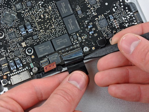
– With one finger, keep the end of the cable retainer pressed down while you gently use the tip of a spudger to lift the other end just a bit and swing it away from the camera cable connector.
– To disconnect the camera cable, simply pull the male end straight out from its socket.
As you nudge the strip (cable retainer) aside, be careful not to knock any tiny components off the logic board—treat them like your favorite snacks on a crowded table! When disconnecting, slide the connector parallel to the logic board’s surface, not upwards like launching a rocket!
The camera cable connector doesn’t have any fancy locking or snapping features to keep it in place. So, to make sure it stays snugly in its socket, Apple cleverly uses a little strip of black adhesive plastic on the side facing the logic board behind the camera cable connector. It’s a simple trick to keep everything secure!
Tools Used
Step 12

Gently pull the connector along the surface of the logic board—think of it as a friendly slide, not a straight-up lift!
– Gently slide the camera cable right out of its socket. Just imagine pulling a sword from a stone, except way easier and a lot less mythical!
Step 13

– Gently slide the flat end of your trusty spudger under the optical drive cable connector and give it a little lift off the logic board. You’ve got this!
Tools Used
Step 14

Take your time and gently lift the connector, not the socket. You definitely don’t want to accidentally nudge the socket off the logic board!
Step 15

– Get ready to rock ‘n’ roll! Use the super cool flat end of a spudger to gently lift the hard drive/IR sensor cable connector up off the logic board.
Tools Used
Step 16


– Get ready to party by removing those two 1.5 mm Phillips screws that are holding the cable cover down on the logic board.
– Lift and celebrate as you dance the cable cover out of its place in the upper case.
Step 17

– Grab your trusty spudger and gently lift that trackpad flex ribbon cable connector off the logic board. You’ve got this!
Tools Used
Step 18

Remember, before you even think about sliding out that keyboard ribbon cable, make sure to give the ZIF socket a friendly unlock first! Those ribbon cables are delicate, so keep it cool and gentle to avoid any unnecessary drama or breakups. You got this!
– Get ready to channel your inner magician as you delicately flip up the locking flap on the ZIF socket for the keyboard ribbon cable. This flap is playing hide and seek at the opposite end of the socket from the keyboard ribbon cable. Get your fingernail in position and voilà, lift it up vertically with finesse!
– Time to put on your tiny superhero cape and use the tip of a spudger to smoothly slide out the keyboard ribbon cable from its cozy socket.
Tools Used
Step 19

– Grab your trusty spudger and gently lift that battery indicator ribbon cable connector off the logic board. You’ve got this!
Tools Used
Step 20


– First up, grab your trusty screwdriver and take out that single 7 mm Phillips screw holding the display data cable retainer snugly to the upper case.
– No worries if that screw decides to play hide and seek in the display data cable ground loop! If you’re swapping out the display, just remember to bring that little guy along to the new unit.
– Now, gently lift off the display data cable retainer from the upper case and you’re one step closer to your repair!
Step 21


– Locate the plastic pull tab attached to the display data cable lock. Give it a gentle twist towards the DC-in side of your device. Stay cool and positive – you’ve got this!
Step 22

Remember to gently pull the connector straight out, keeping it parallel to the logic board’s surface. No need to yank it up from its socket!
– Gently wiggle and pull the display data cable connector out of its socket like you’re giving it a friendly little nudge.
Step 23


– Hey there, grab your spudger and gently lift that little flap holding the keyboard backlight ribbon cable in place. You’ve got this!
– Carefully slide that ribbon cable straight out of its socket. Nice and easy does it!
Tools Used
Step 24

Hold up! Don’t yank out that logic board just yet! Make sure to disconnect the sneaky components hiding on the underside that are still cozying up to the upper case.
– Time to unscrew some mysteries! Remove the following screws:
Step 25

Hold up! Don’t pull the logic board all the way out just yet! Keep it connected for now.
– Gently raise the logic board assembly from the left edge, easing it out of the upper case. Watch out for the port side—it might snag on its way out. Keep it smooth and easy!
Step 26

– Gently lift the logic board just enough to sneak a spudger underneath and pop the microphone free from the upper case. It’s like a little techy treasure hunt!
– Carefully slide the logic board away from those pesky port openings and lift the whole ensemble out of the upper case. Ta-da!
– Before you put the logic board back in, it’s super handy to press the microphone into its cozy spot in the left speaker. It’ll stay put and make your life easier!
Tools Used
Step 27

– Gently coax the logic board away from the port openings and hoist the assembly out of the upper case like you’re lifting a treasure chest.
– Before you pop the logic board back in, it’s a slick move to tuck the microphone back into its cozy spot in the left speaker—helps it stay put!
Step 28

– Place the logic board on a cushy, flat surface, heat sink side up, and get ready for some action!
– Unplug the DC-In Board connector from the logic board by giving it a smooth, straight pull—it’s time to disconnect and chill!


