How to Replace MacBook Pro 15 Front Display Bezel – DIY Tutorial
Duration: 45 minutes
Steps: 42 Steps
Heads up, tech whiz! Make sure you have all your tools lined up for a smooth repair ride. If you hit a snag, remember, help is just a click away at schedule a repair.
Step 2

– Pop off those three Phillips screws from the memory door.
Step 3

– Give the memory door a little lift to grab it, then slide it toward yourself and pull it away from the case like you’re unveiling a magic trick!
Step 4

– Unscrew the two 2.8 mm Phillips screws chilling by the latch in the battery compartment.
Step 5

– Time to get those hands working! Remove the 6 screws: one step closer to victory!
Step 6

– Unscrew those four 3.2 mm Phillips screws on the port side of your computer and let the adventure begin!
Step 7

– Give your computer a little twist and turn it 90 degrees! Now, let’s get those two 3.2 mm Phillips screws out from the back. You’ve got this!
Step 8

– Twist the computer 90 degrees once more and whip out those four 3.2 mm Phillips screws from the computer’s side. Keep it going, you’re doing awesome!
Step 9

Take it slow! Don’t just rip off the upper case like you’re opening a bag of chips. Remember, it’s connected to the logic board with a ribbon cable. Let’s keep it chill and careful!
– Start by lifting the rear of the case and gently slide your fingers along the sides to loosen it. Keep going until the sides are free, then gently rock the case up and down to disengage the front clips (watch out for those sneaky hidden plastic clips!).
Step 10

– Gently detach the trackpad and keyboard ribbon cable from the logic board, peeling off any tape that might be in the way.
– Carefully lift off the upper case.
Step 11

– Pop off the three antenna cables hooked to the Airport Extreme card.
– Apple was cool enough to label where each color antenna cable goes – just check those tags when you’re reconnecting. If you need help, you can always schedule a repair
Step 12

– Unleash the Airport antenna cables from their cozy spot within the left speaker.
Step 13

– Unplug the iSight cable from the logic board by nudging it left and out of its connector.
Step 14

– Pop off the inverter cable from the logic board using a spudger. Just slide the spudger under the cable and give it a gentle lift. Voila!
Tools Used

Step 15

– Gently slide the display data cable off the logic board like you’re whisking it off to a dance. Keep it smooth and sideways, folks!
Step 16

– Unscrew the shiny silver T6 Torx that’s keeping the ground loop of the display data cable tight to the casing. It’s just a little twist away from freedom!
Step 17

– Keep the display steady with one hand while unscrewing the next 3 screws:
Step 18

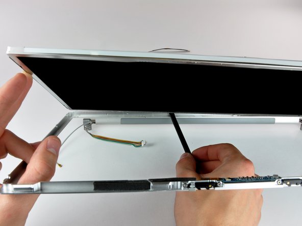
– Grab the display assembly with both hands and gently lift it away from the computer like you’re unveiling a surprise gift.
Step 19


– Unscrew the two 5 mm Phillips screws hanging out on the lower left and right corners of the display. Just two screws, friend, and you’re on your way!
Step 20


Hey there! Make sure not to wedge your spudger between the plastic strip and the back casing—let’s keep things friendly!
– Pop the flat end of a spudger in perpendicular to the display right between that sneaky plastic strip on the rear bezel and the front bezel. It’s like you’re picking the lock to tech freedom!
– Keep that spudger in place and give it a little twist away from the display. It’s like opening a can of future where the bezels part ways!
– Skedaddle along the left edge of the display until the rear bezel gives a little cheer and pops away from the front bezel evenly. You’re doing great!
Tools Used
Step 21


– Wedge the flat end of a spudger between the plastic strip on the rear bezel and the front bezel of the display, positioning it perpendicularly.
– Keeping the spudger in place, give it a twist away from the display to start loosening the bezel camaraderie.
– Slide along the right side, continuing until the rear bezel and the front bezel are no longer best buddies.
Tools Used
Step 22


– Wedge the flat end of your spudger between the front bezel and the plastic strip clinging to the rear bezel at the bottom corners of the display. It’s like unlocking a secret door!
– Twist that spudger towards the rear bezel to convince it to part ways with the front bezel. It’s almost like magic!
– If needed, gently widen the gap between the lower edge of the rear bezel and the clutch cover until they decide to break up completely. Freedom!
Tools Used

Step 24
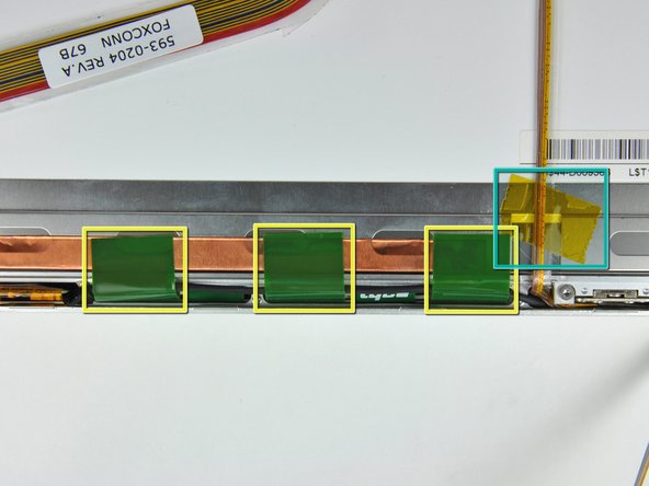

– Let’s kick things off by gently peeling away the yellow kapton tape from the bottom left corner of your display.
– Next up, carefully remove the tape that’s holding the display data cable and camera cable snugly to the display.
– Now, it’s time to peel off those three green antenna ground straps from the copper tape along the bottom edge of the LCD. You’ve got this!
– Finally, take off the piece of tape that’s keeping the camera cable attached to the LCD. Almost there!
Step 25

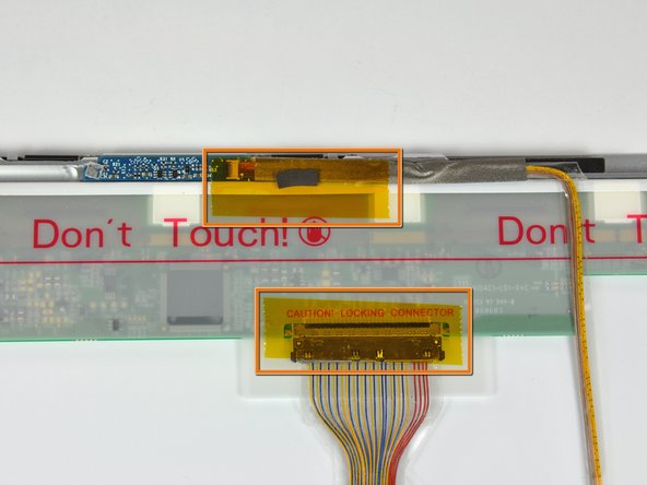
– Gently lift the camera cable from the foam tape along the top edge of the LCD. If you need help, you can always schedule a repair.
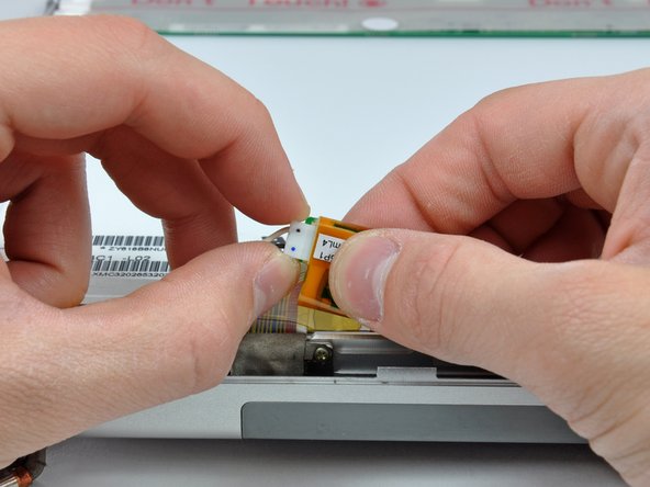
Step 26

Gently pull the cable straight out, keeping it aligned with the LCD’s surface.
– Use a spudger tip to carefully flip the ZIF connector bar up and release the camera cable.
– Gently pull the camera cable away from its socket on the camera board. If you need help, you can always schedule a repair
Tools Used
Step 27

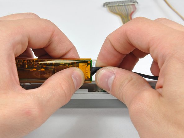
Gently pull the connector straight out, keeping it level with the LCD surface. You’ve got this!
– Gently wiggle and pull the display data cable connector away from its cozy home in the LCD socket.
Step 28


– Take out the four black Phillips screws running along the left and right sides of the display (that’s eight screws in total). If you need help, you can always schedule a repair.
Step 29

When you’re applying the adhesive, make sure it grabs onto that sleek steel strip that runs along the edge of your LCD. As you gently pry the LCD away from the front panel, remember to focus on separating the front panel from that steel strip. You’ve got this!
Get ready to tackle the next few steps where you’ll need to gently pry the LCD away from the sticky adhesive hugging the top and bottom edges of the front bezel. A heat gun can be your best buddy here, helping to warm up that adhesive just enough to keep the LCD safe and sound during its grand exit.
Step 30

– Gently work your way along the top edge of the LCD, prying the steel strip away from the front bezel. If you need help, you can always schedule a repair.
Step 31

– Now that you’ve got the top edge free, gently lift the LCD out of the front bezel just enough to pry the steel strip along the lower edge of the LCD away from the front bezel.
– Keep prying along the lower edge of the LCD until it’s free from the adhesive on the front bezel. If you need help, you can always schedule a repair
Step 32

– Hoist the inverter out of its cozy clutch cover nook.
– Unplug the LCD backlight connector from its hangout on the inverter board.
Step 33

– Hoist the LCD from its snazzy front bezel, but watch out for those sneaky cables that might snag.
Step 34

Be gentle with that inverter cable! Pulling it too far out of the clutch cover can damage its delicate ground loop. Treat it like the precious little thing it is!
– Gently lift the inverter out of the clutch cover like you’re unveiling a surprise!
– Unplug the inverter cable by giving it a little tug away from the socket on the inverter board. Easy peasy!
– Carefully remove the inverter and set it aside, ready for its next adventure.
Step 35

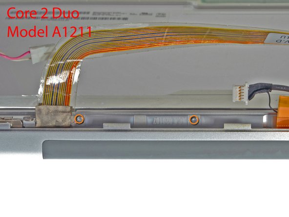
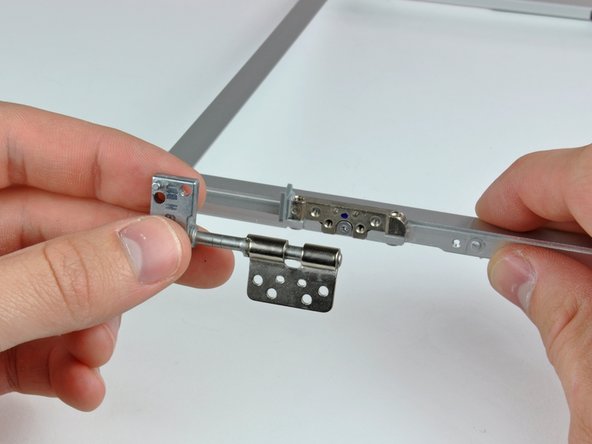
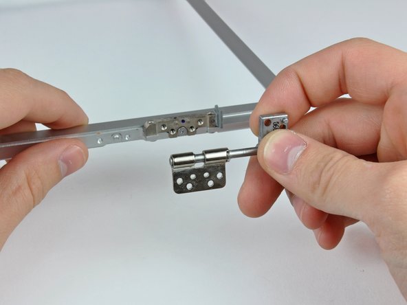
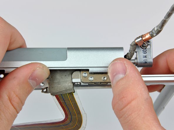
– Got a Core Duo machine? Check out picture 1 and go ahead and unscrew those three Phillips screws that are holding the clutch assembly to the lower edge of the front display bezel, right by the display data cable. You’ve got this!
– If you’re working with a Core 2 Duo Model A1211, take a look at picture 2. You’ll want to remove those two Phillips screws that connect the clutch assembly to the lower edge of the front display bezel near the display data cable. Easy peasy!
Step 36

– Unscrew that lone black Phillips screw hiding behind the display data cable.
– Gently slide the small steel bracket away from the right clutch hinge and take it out of the clutch assembly.
Step 37

– Unscrew those three Phillips screws hanging out along the inside of the clutch cover, right by the inverter/camera cable. You’ve got this!

Step 39

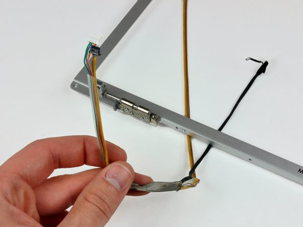
– Gently guide the display data and inverter/camera cables around the clutch hinges and detach both cables with care.