MacBook Pro 15 Logic Board Replacement DIY Guide
Duration: 45 minutes
Steps: 29 Steps
Heads up! Make sure you have all the necessary tools and parts before you start your repair adventure. If you hit a snag, don’t worry—help is just a click away at schedule a repair.
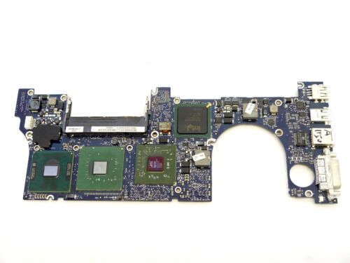
This motherboard hosts all ports on the right side. If you need help, you can always schedule a repair.
Step 1

– Put on your superhero gloves and show that battery who’s boss by gently nudging those release tabs away from it. Once it feels unloved, lift it up and out of your device with a big smile on your face.
Step 2

– Start by gently taking out those three identical Phillips screws from the memory door—easy peasy!
– Don’t forget to keep track of which screws came from where; it’ll make putting everything back together a breeze!
Step 3

– Give that memory door a gentle lift until you can grab hold of it. Then, slide it towards yourself, pulling it away from the casing with ease.
Step 4

– Unscrew the two chic Phillips screws chilling in the battery compartment near the latch.
Step 5

– Alright, grab your tools and let’s get zippy! Unscrew these 6 little rascals:
Step 6

– Unscrew the four Phillips screws chilling on the port side of the computer. It’s like a little treasure hunt!
Step 7

– Twist your device a cool 90 degrees and unscrew the duo of Phillips screws chilling at the back of the computer.
Step 8

– Time to bust a move! Rotate your computer 90 degrees once more and bid farewell to those four Phillips screws on the side of your computer.
Step 9

Take it easy when removing the upper case! It’s connected to the logic board with a ribbon cable, so give it a gentle touch.
– Start by lifting the back of the case and wiggle those fingers along the sides to loosen it up. Keep working around until the sides pop free. Then, give the case a gentle rock back and forth to unhook the front. Heads up—this part is a bit of a puzzle! Watch out for those sneaky tabs above the DVD reader that you’ll need to pull out vertically.
– Keep an eye on the two tiny tabs on the front left of the upper case; they might get a bit bent out of shape during removal. No worries, though! Just give them a little tweak back into place when you’re putting everything back together so they slide into the grooves of the lower case smoothly.
Step 10

– Unplug the trackpad and keyboard ribbon cable from the logic board, peeling off any tape that’s cramping your style.
– Lift off the upper case like you own the place.
Step 11

– Gently disconnect the vibrant orange SuperDrive ribbon cable from the logic board, peeling off any tape when necessary.
Step 12

– Here’s the fun part – time to unscrew 3 little buddies:
Step 13

– Carefully lift the optical drive out of the computer. If you need help, you can always schedule a repair
Step 14

– Alright tech hero, let’s get groovy by popping out the hard drive and ExpressCard connectors from the left side of that logic board. If you need help, you can always schedule a repair.
Step 15

– Get ready to party by disconnecting the eight indicated connectors from the logic board, and dance off that tape as needed!
Step 16

– Time to work some magic – grab a trusty spudger and delicately lift up the charming brown plastic flap that’s keeping the left ambient light sensor cable snug as a bug on the logic board.
– Gently coax the left ambient light sensor cable to the left and elegantly out of its cozy connector.
Tools Used

Step 17

– Time to get your tools out! Unscrew that shiny silver T6 Torx screw that’s holding the ground loop on the display data cable to the casing. You’ve got this!
Step 18

– Unscrew the shiny silver T6 Torx screw that’s keeping the clear plastic shield in place over the right ambient light sensor. Just one screw, you got this!
– Gently lift away the clear plastic shield from the right ambient light sensor. Easy does it!
Step 19

– Gently remove the orange Kapton tape that’s keeping the right thermal sensor cable cozy on the logic board.
Step 20

– Alright, let’s dive in and unscrew the following 16 screws, moving cables as needed. Keep your spirits up and tools ready!
Step 21

– Nudge the display data cable to the right, clearing off any tape that gets in the way.
– Gently peel away and discard the orange foil shield near the right speaker.
Step 22

– Twist the speaker clockwise about 30 degrees until it pops off the logic board like a champ!
Step 23

– Time to free those speaker wires! Gently lift the gray and black cables off the logic board—watch out for any sneaky tape holding them down.
Step 24

– Gently detach the iSight and inverter board cables from above the left fan like you’re peeling a banana.
– While pressing down the logic board with one hand, use your other hand to raise the left fan from its cozy home. There’s a sneaky strip of black tape holding the fan to the heat sink—carefully peel it off as you lift the fan.
– Just pop the fan right above the Airport card. No need to completely remove the fan from its tech habitat!
Step 25

Step 26

– Gently hoist up the left side of the logic board and unplug the snazzy multi-colored power cable from its hideout at the bottom of the board.
Step 27

Hold up, don’t yank the logic board out just yet! It’s still tethered by a sneaky cable. And hey, when putting your MacBook Pro back together, give those chips a spa treatment by cleaning off that old thermal goop. Check out our snazzy guide on slathering on new thermal paste to get those surfaces shiny and ready.
– Hold onto the logic board by its left edge and the slender part, then gently twist it out of the lower case. You’ve got this!
Step 28

– Unplug the right thermal sensor cable from the bottom of the logic board, right near the DVI port. If you need help, you can always schedule a repair
Step 29

Got two RAM chips in there? No problem! Just follow the same steps for the second one and you’ll be all set. If you need help, you can always schedule a repair.
– Gently press on the tabs on both sides of the RAM chip at the same time. These little guys hold the chip snugly in place, and releasing them will let the chip pop up like a surprise!
– Now, carefully pull the chip straight out from its connector. You’ve got this!


