DIY Guide to Replace MacBook Pro 15 LCD Panel – Step-by-Step Tutorial
Duration: 45 minutes
Steps: 32 Steps
Heads up, champ! Make sure you’ve got all your tools ready and your workspace clear. A tidy space is a happy repair space!
Swap out that busted LCD without having to ditch the whole screen assembly. Keep the rest, just refresh the part that counts!
Step 1

– Press both battery release tabs away from the battery with your fingers, and lift that battery out of the computer. If you need help, you can always schedule a repair
Step 2

– Unscrew the three identical Phillips screws from the memory door with a smile! Remember to keep track of which screws came from where; it’ll make putting everything back together a breeze.
Step 3

– Gently lift the memory door just enough to get a good grip on it, then slide it toward you and away from the casing like you’re pulling a tablecloth in a magic trick!
Step 4

– Unscrew the two Phillips-head party crashers chilling near the battery compartment latch.
Step 5

– Let’s spice things up by grabbing your trusty screwdriver and bid farewell to these 6 pesky screws:
Step 6

– Time to get your screwdriver ready! Unscrew those four Phillips screws on the port side of your computer and let’s keep this repair rolling!
Step 7

– Give the computer a fun little twist of 90 degrees, then kindly ask those two Phillips screws at the back to take a break.
Step 8

– Give your computer a cool 90-degree spin once more and whisk away the four Phillips screws from the side. Keep it groovy!
Step 9

Whoa there, tiger! Don’t just rip off the upper case like a band-aid. It’s still hooked up to the logic board with a ribbon cable. Gently does it, superstar!
– Start by lifting the rear of the case, and shimmy your fingers along the sides to loosen it. Keep working around till the sides are free. Now comes the fun part! You might need to wiggle the case up and down a bit to release the front. Those four sneaky tabs over the DVD reader need a vertical tug to come out.
– Watch out for the two tiny tongues on the front left of the upper case; they might get a bit bent out of shape during removal. When putting it back together, just give them a little pep talk and bend them back into the grooves of the lower case.
Step 10

– Unplug the trackpad and keyboard ribbon cable from the logic board, peeling off any tape that gets in the way.
– Whisk away the upper case like you’re unveiling a magic trick.
Step 11

– Unhook those two snazzy antenna cables from your Airport Extreme card, buddy.
– Connect the white antenna cable to the left side of the Airport Extreme card for some smooth surfing.
Step 12

– Unravel the Airport antenna cables from their hangout in the left speaker’s groove.
Step 13

– Gently detach the iSight, inverter, and left fan cables from the logic board by pulling them in the direction they naturally go.
Step 14

– Unplug that display data cable from the logic board and give it a little breather!
Step 15

– Get ready for some action! Remove that silver T6 Torx screw that’s keeping the ground loop on the display data cable attached to the casing.
Step 16

– Hold the display steady with one hand while you take out these 3 screws:
Step 17

– Grab the display assembly with both hands, and gently lift it up and away from the computer. You’re doing great!
Step 18


– Take out the two 5 mm Phillips screws chilling at the lower left and right corners of the display. Just two screws, easy peasy!
Step 19


– Slide the flat end of a spudger between the plastic strip on the rear bezel and the front bezel. It should be perpendicular to the face of the display. It’s like you’re the mediator in a tiny bezel standoff!
– With your trusty spudger still in place, give it a gentle twist away from the display. This little pivot is all it takes to start the bezel breakup.
– Saunter down the left edge of the display, continuing with your spudger as your guide, until the rear bezel parts ways evenly from the front bezel. It’s like they’re saying, ‘It’s not you, it’s me,’ all along the edge!
Tools Used

Step 20


– Pop the flat end of your spudger right into the mix! Slide it perpendicular to the display, right between that clingy plastic strip on the rear bezel and the oh-so-eager front bezel.
– Keep that spudger in place and give it a little twist away from the display to start the magic of separating the front and rear bezels.
– Saunter down the right edge of the display, working that spudger until the rear bezel loosens up nicely from the front. Keep it even to avoid any bezel drama!
Tools Used
Step 21


– Gently slide the flat end of a spudger between the front bezel and the plastic strip that’s hanging out with the rear bezel near those sneaky screw holes at the bottom corners of the display.
– Give that spudger a little twist towards the rear bezel to help them part ways.
– If they’re being stubborn, just widen that gap between the lower edge of the rear bezel and the clutch cover until they decide to let go of each other completely.
Tools Used

Step 23
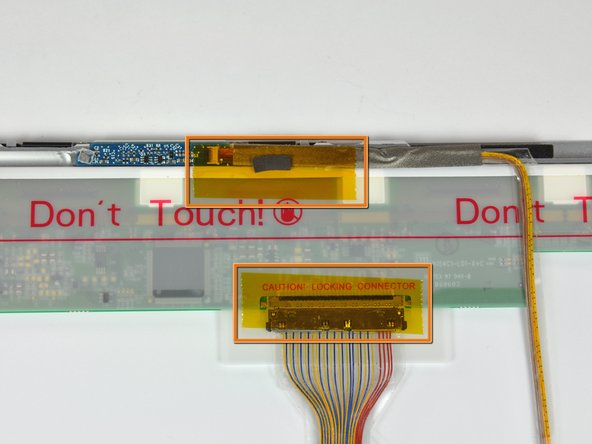

– Let’s start by gently peeling away those pieces of yellow kapton tape from the bottom left corner of the display. Easy peasy!
– Next up, remove the tape that’s keeping the display data cable and camera cable snug against the display. You’ve got this!
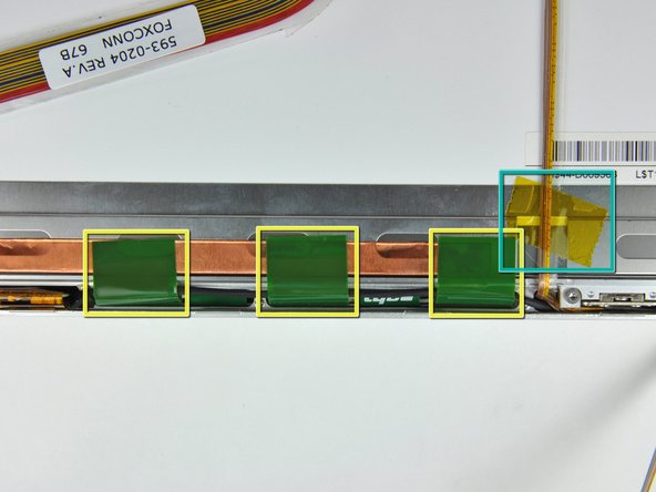
– Now, it’s time to carefully peel off those three green antenna ground straps from the copper tape along the bottom edge of the LCD. Just a little wiggle and they’ll come right off!
– Finally, take off the piece of tape that’s securing the camera cable to the LCD. Almost there!
Step 24

– Gently lift the camera cable away from the foam tape at the top edge of the LCD. You’ve got this!
Step 25

Gently pull the cable along the LCD’s surface, keeping it nice and parallel. You’ve got this!
Step 26

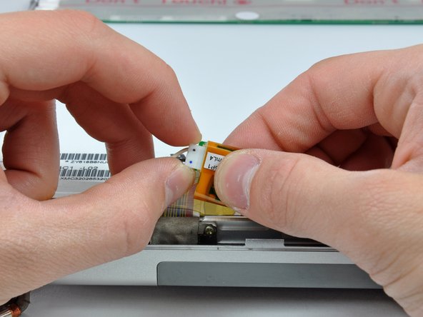
Gently slide the connector out, keeping it parallel to the LCD’s surface. You’ve got this!
– Gently unplug the display data cable connector from its snug spot on the LCD.
Step 27


– Unscrew the eight snazzy black Phillips screws chilling on the left and right edges of the display. Keep track of them!
Step 28

Heads up! The adhesive is snug around a sleek steel strip bordering the LCD. When you’re separating the LCD from the front panel, make sure you’re peeling it off the steel strip, not just yanking them apart. Keep it smooth, keep it cool!
Tools Used
Step 29

– Slide along the top edge of the LCD and gently coax the steel strip to detach from the front bezel. Keep the vibes positive, you’re doing great!
Step 30

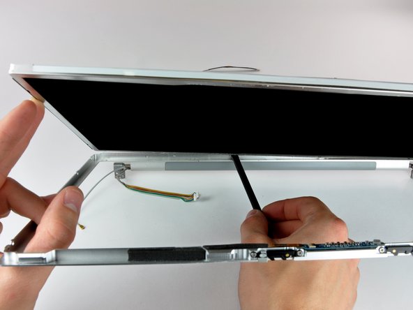
– Alright, you’ve loosened up the top edge—nice work! Now, gently lift the LCD just a tad out of the front bezel to make some space for wiggling out that steel strip along the lower edge of the LCD from the front bezel.
– Keep on prying along the lower edge of the LCD until it breaks free from that sticky adhesive on the front bezel. You’re doing great!
Step 31

– Hoist that inverter out of the clutch cover like you’re lifting a treasure chest!
– Unplug the LCD backlight connector from its cozy nook on the inverter board.
Step 32

– Hoist that LCD out of its comfy front bezel throne, but watch out for those sneaky cables trying to tag along!


