DIY Guide to Replace MacBook Pro 14″ Late 2023 Logic Board
Duration: 45 minutes
Steps: 65 Steps
Just a heads-up, your Touch ID will go on a little vacation if you swap out the logic board!
Ready to jazz up your MacBook Pro 14″ from late 2023 with some DIY magic? Dive into this guide to swap out the old logic board for a fresh one, featuring those snazzy M3 Pro and M3 Max chips! Just a heads up—your Touch ID will play hard to get after this switcheroo, as it’s originally matched with your old board, and without Apple’s secret handshake (aka their calibration process), even a swanky genuine sensor from another MacBook won’t flirt with your new board. Oh, and don’t be puzzled if some pics look a tad different; they’re just from another model but will guide you just fine!
Step 1


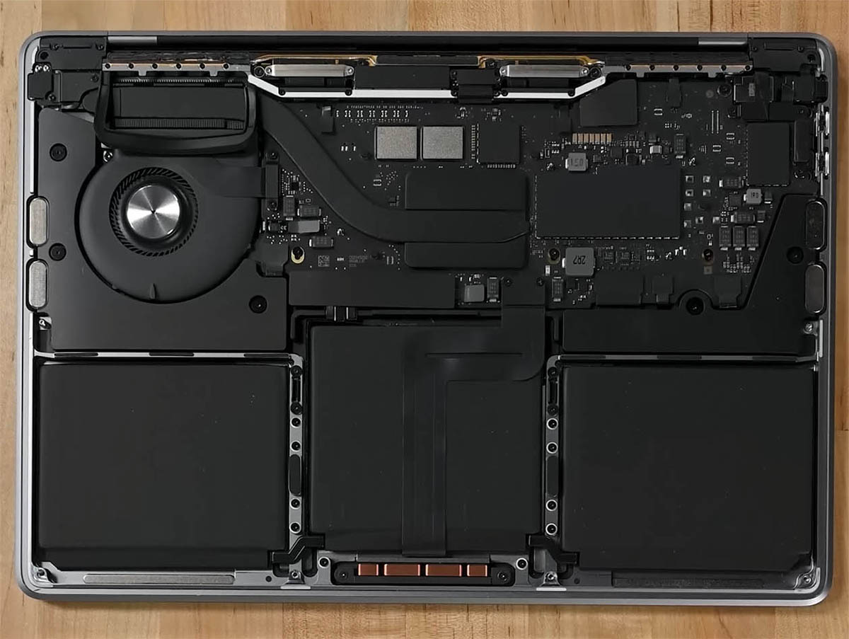
– Power down your MacBook, give it a rest by closing the lid, and gently flip it over. Remember, no peeking until the battery is disconnected!
– Unhook the MagSafe and any gadgets hanging off your MacBook. Let’s keep it tidy!
Step 2


Before diving in, make sure your MacBook Pro is switched off and unplugged. Close it up, flip it over, and let’s get started on the fun part!
During this repair adventure, make sure to keep tabs on each screw and pop them back in their original hangouts to avoid any party fouls with your device.
– Grab your P5 Pentalobe driver and unleash those eight screws holding the lower case captive!
Step 3


– Stick a suction cup near the front edge of the lower case, just between the screw holes. It’s like playing with a mini plunger!
– Give that suction handle a hearty tug to create a wee bit of space under the lower case. It’s like opening a treasure chest, but for tech!
Tools Used

Step 4


– Pop an opening pick into the gap you just created. Party started!
– Whoosh the opening pick around the nearest corner and cruise it halfway up the side of the MacBook Pro. Keep the groove going!
Step 5


– Now, let’s do that dance again on the flip side. Grab your opening pick and shimmy it into place to pop the second clip free. Keep the groove going!
Step 6


The back edge of your MacBook has some sassy clips that need a bit of muscle to loosen up. Don’t shy away from using some gloves—those lower case edges can be quite snappy. It’s all part of the adventure, so put some elbow grease into it and show those clips who’s boss!
– Gently tug the lower case away from the back edge, one corner at a time, to free those sneaky sliding clips.
Step 7


– Pop off the lower case with flair.
– When putting the lower case back, just reverse the charm!
Step 8


– Gently peel away any tape that’s hiding the battery board data cable connector on the logic board. It’s like uncovering hidden treasure!


Step 10


– Gently slide the battery board data cable out of its socket on the logic board to disconnect it. You’ve got this!
Step 11

Your MacBook might be rocking some Torx Plus screws, but no worries, your regular Torx bits will do the trick just fine. Just remember to keep the pressure steady and straight to dodge any chance of stripping those screws!
– Grab your T3 Torx driver and whisk away those two tiny 2.1mm-long 3IP Torx Plus screws that are holding the trackpad cable bracket like it’s guarding treasure. It’s just a couple of screws standing between you and victory!


Step 13


To snap back these press connectors, just line up one side and give it a gentle tap until you hear a satisfying click, then do the same on the opposite side. Steer clear of pushing in the middle to avoid a connector catastrophe with bent pins!
– Grab your spudger and let’s pop off that trackpad cable connector like a pro! Just slide the flat end under the connector on the logic board and gently lift it up. Easy-peasy!
Tools Used


Step 15


– Unstick any tape hiding the battery board data cable connector beneath the big ol’ pancake screw.


Step 20


Gently lift the connector just high enough to avoid any accidental connections during your awesome repair adventure—keep it under 45 degrees to make sure you don’t stress its hinge. Keep it chill and steady!
For a touch of safety flair, slip something like a playing card slice between the connector and the board. It’s your little guardian shield!
Step 21


– Grab your trusty T3 Torx screwdriver and show those three 2.1 mm screws who’s boss! They’re just hanging out, holding the antenna board bracket and coaxial cable cover to the frame. Time to evict them!
Tools Used

Step 22


– Grab your tweezers or just use your fingers to gently remove the cover sitting atop the antenna bar’s coaxial cables. Let’s keep it cool and smooth!
Step 23


– Use a spudger to gently lift and disconnect the antenna bar’s coaxial cable.
– Do the same for the remaining two cables.
– When putting it back together, reconnecting these can be a bit of a puzzle. Position each connector right above its socket and press down with the spudger’s flat side until you hear a satisfying snap. They should click right into place.
Tools Used
Step 24


– Grab your T3 Torx driver and whisk away those four 2.1 mm screws holding down the screen cable covers. Let’s get to it!
Step 25


– Grab your tweezers or just use your fingers to whisk away those two sneaky screen cable covers off the logic board. Easy peasy!
Step 26


– Grab the flat end of your spudger and give a gentle pry to disconnect the right-most screen cable press connectors from the logic board. Like a pro!
Tools Used
Step 27


Watch out! Make sure you don’t lever against those snazzy surface-mounted buddies near the press connector.
– Now, just like you did before, go ahead and disconnect that last press connector chilling at the top left of the logic board. You got this!
Step 28


– Gently peel away any sticky tape hiding the microphone cable connector.


Step 30


– Slide out the microphone cable from its cozy home on the logic board like a pro.
Step 31


– Grab your T3 Torx driver and get ready to remove those nine snazzy 2.1 mm screws holding the right cable covers in place on the frame!
Step 32


– Grab your tweezers or just use your fingers, and let’s pop off those five right cable covers. You got this!
Step 33


– Gently peel back any tape that’s hiding the right speaker cable. Let’s free that cable!


Step 35


– Slide out the right speaker cable from its cozy home on the logic board to disconnect it.
Step 36


– Grab your spudger and pop off that headphone jack’s press connector like a pro!
Tools Used
Step 37


– Grab your spudger and pop off the right USB-C ports’ press connectors like a boss.
Tools Used


Step 40


– To begin this awesome journey of repair, grab your trusty T3 Torx driver and liberate those four screws holding the left cable covers hostage on the frame.
Step 41


– Get ready to tackle this task with a smile! Grab those tweezers or use your trusty fingers to delicately lift off the two left cable covers.
Step 42


– Gently peel away any tape that’s hiding the left speaker cable. It’s like uncovering hidden treasure!


Step 44


– Slide out the left speaker cable from its cozy spot on the logic board to disconnect it.
Step 45


– Grab your spudger and gently pop off the left USB-C port’s press connector like a pro.
Tools Used
Step 46


The Touch ID sensor cable is snugly stuck to the frame. If the sticky stuff doesn’t let go when unplugging the press connector, sneak an opening pick beneath the cable to gently persuade it to detach.
Step 47


– Gently peel away any tape that’s keeping the keyboard and the keyboard backlight cable connectors under wraps.
Step 48


– Grab your spudger and gently coax the locking flap on the ZIF connectors for the keyboard cables to lift up. It’s like waking a sleepy kitten—be gentle!
Tools Used
Step 49


– Slide out the keyboard and keyboard backlight cables from their cozy homes on the logic board to disconnect them.
Step 50


– Gently peel back any tape that’s chillin’ over the right fan cable connector.


Step 52


– Unplug the right fan cable by gently gliding it out from its cozy spot on the logic board. Easy does it!
Step 53


The right fan cable just can’t let go of the logic board—it’s slightly stuck on there!
– Grab your tweezers and gently slide the fan cable away from the logic board to release that sticky adhesive. It’s like setting it free—go, little cable, go!
Step 54


– Now, let’s give the left fan the same groovy disconnect and shuffle as we did with the right one.
Step 55


– Whip out your tool kit and unscrew the four sleek black screw covers from the logic board. Let’s get rolling!
Step 56


– Grab your T5 Torx driver and get ready to unleash those 11 screws holding the logic board in place!
Step 57


– Grab your T6 Torx driver and unscrew the three screws holding down the logic board. Let’s get this party started!
Step 58


– Wedge a spudger into the right edge between the logic board and the frame.
– Give it a little pry to pop the logic board out of its cozy clips.
Tools Used
Step 59


– Slide a spudger in between the bottom edge of the logic board and the frame like you’re parting the seas.
– Gently nudge upwards on the spudger to pop the logic board free from its snug little clips.
Tools Used
Step 60


– Carefully hoist the logic board from the right side to free it from its snug little pegs.
– Slide the logic board to the left, detaching the HDMI and SDXC ports from their cozy slots in the frame.
– Lift off the logic board and bid it farewell.
Step 61


– When you’re putting things back together, make sure to do the following:
Step 62


– Flip the logic board to show its wild side with the heat sink screws staring right at you!
– Grab a T5 Torx driver and unscrew the four 3.9 mm screws that are holding the heat sink tight to the logic board.
– When putting it back together, start by getting those screws snug, but not tight. Line up the brackets and heat sink just right, then secure them firmly in a criss-cross pattern to make everything nice and even.


Step 64


– Gently lift the logic board off the heat sink using your fingers—no need for a superhero cape here!
– Time to say goodbye to the heat sink. Remove it carefully.
– You’ll notice a thick, grey thermal compound connecting the logic board and heat sink below. Once the heat sink is off, check out our thermal paste guide to learn how to clean off the old thermal compound and replace it with a suitable new one. You got this!
Step 65

– Voila! You’ve successfully isolated the logic board!