How to Replace MacBook Pro 13 Heat Sink: Step-by-Step Guide
Duration: 45 minutes
Steps: 21 Steps
Hey there! If you’re feeling stuck or unsure about this step, remember that we’re here to help you out. Feel free to reach out and schedule a repair with our friendly team at Salvation Repair. Let’s get this device back up and running in no time! 🛠️😊
The heat sink is like a cool breeze for your processor, keeping it chill and in high spirits.
Step 1

– Unscrew the 10 screws that are keeping the lower case attached to the MacBook Pro 13″ Unibody. It’s like a treasure hunt, but instead of gold, you’re after tech glory!
Step 2

– Gently lift the lower case a tad and slide it toward the back of the computer to unhook those nifty mounting tabs.
Step 3

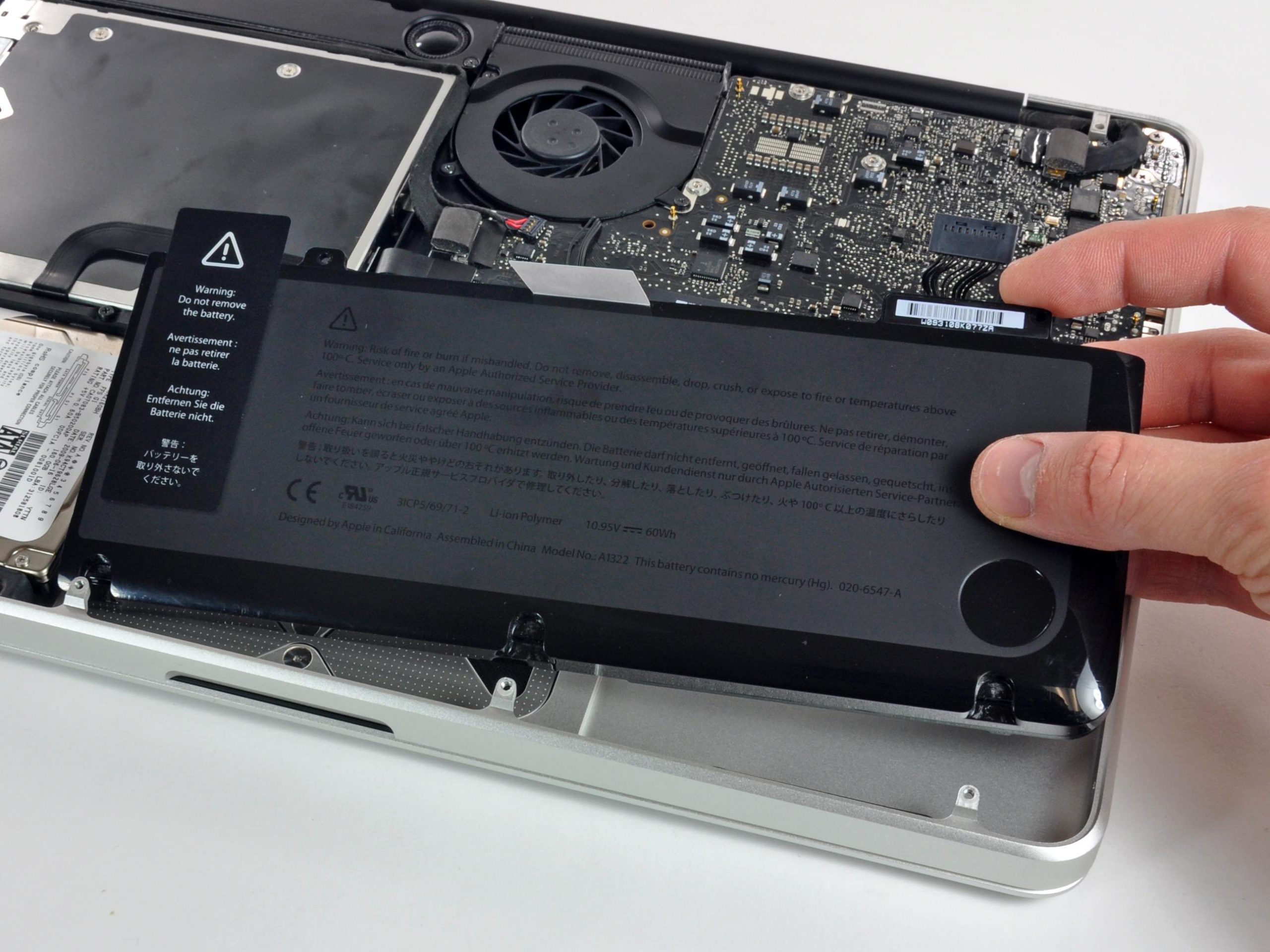
Just a friendly heads up! For your safety, it’s best to unplug the battery connector from the logic board to keep any pesky electrical surprises at bay.
– Grab your trusty spudger and gently use its flat end to nudge the battery connector up and out of its cozy socket on the logic board.
Tools Used

Step 4


– Grab your spudger and gently wiggle the fan connector free from its home, then lift it straight up from the logic board.
Check out the second and third pictures to spot the fan socket and connector! Just a heads up: when you’re using your spudger to gently lift the fan connector straight up and out, be super careful not to snap that plastic fan socket off the logic board. The layout in the second picture might look a bit different from your device, but no worries—the fan socket is still the same. If you need help, you can always schedule a repair!
Tools Used
Step 5

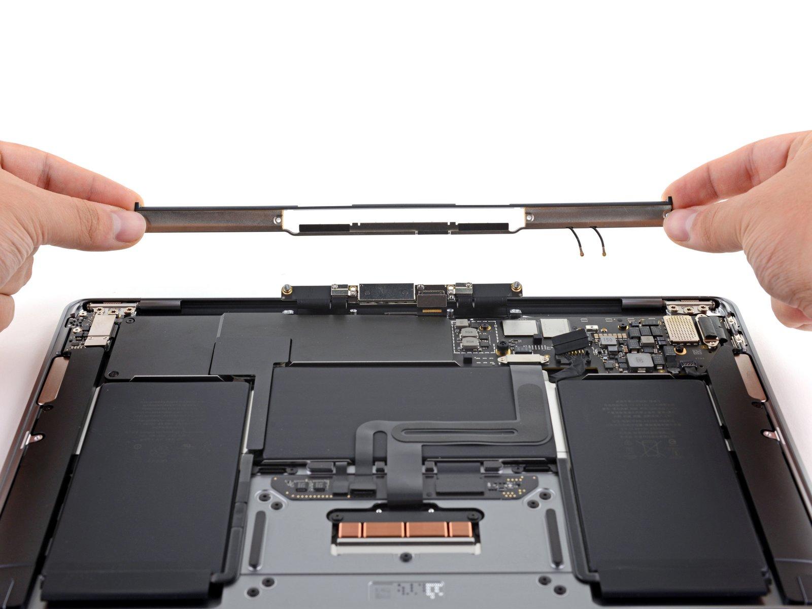
– Unscrew the trio of screws that are keeping the fan snug against the upper case:
Step 6

– Hoist that fan right out of its cozy upper case home!


Step 9

– Grab the flat end of a spudger and give the subwoofer and right speaker connector a gentle pop off the logic board.
Tools Used
Step 10

– Gently slide the camera cable connector towards the optical drive to unplug it from the logic board. Easy peasy!
Alright, it’s time to unhitch that camera cable! Typically, there’s a nifty little plastic retainer glued on to keep everything snug. Make sure to slide that out of the way before you pop the cable off. It’s like telling someone ‘excuse me’ before you scoot past them on the bus!
Watch out! This socket is metal and likes to play hard to get, so it’s easily bent. Make sure the connector and its socket on the logic board are perfectly lined up and ready to tango before you bring them together.
Step 11


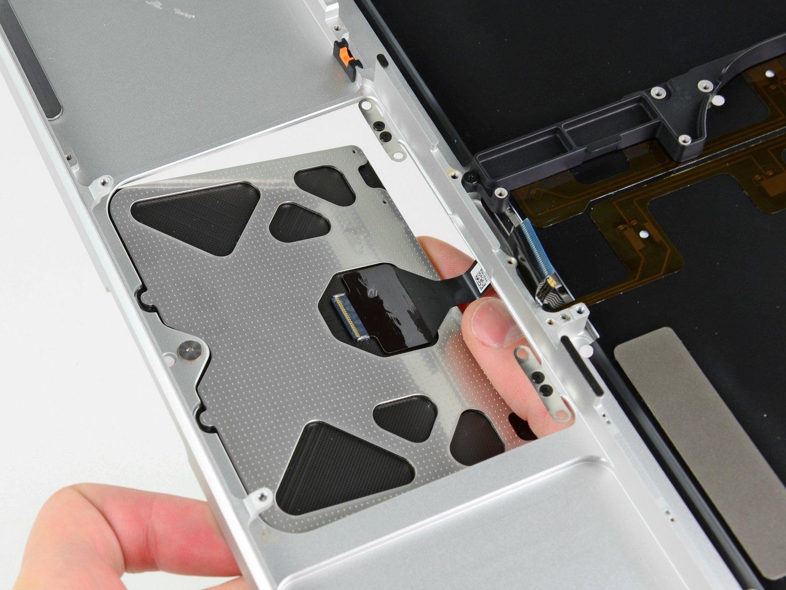
– Grab the flat end of your trusty spudger and gently pop the optical drive, hard drive, and trackpad cable connectors off the logic board like a pro.
Tools Used
Step 12


– Pop that cable retaining flap open with your fingernail or a spudger like you’re opening a treasure chest. It’s just for the ZIF socket of the keyboard ribbon cable, so go on, flip it!
– Now, nudge that keyboard ribbon cable out of its socket with your spudger. Slide it out like you’re pulling a magic trick. Ta-da!
Tools Used
Step 13

– Gently remove the little strip of black tape from the keyboard backlight ribbon cable socket. Let’s keep things tidy!
Step 14


– Grab your spudger and pop open the cable retaining flap on the ZIF socket like you’re opening a treasure chest. This is for the keyboard backlight ribbon cable.
– Now, slide that keyboard backlight ribbon cable out of its socket with your spudger like a magician pulling a rabbit out of a hat.
Tools Used
Step 15

– Grab the flat end of your spudger and give that battery indicator cable connector a gentle nudge off the logic board. It’s party time for the spudger!
Tools Used

Step 17

– Alright, let’s unscrew some screws! Here’s what you need to do next:


Step 19


Watch out! Make sure you don’t accidentally yank out the delicate connector plug of the microphone assembly. Handle it like it’s the crown jewels!
– Gently lift the left edge of the logic board and keep going until those ports are free from the upper case’s clutches.
– Slide the logic board away from the upper case’s embrace and take it out, but watch out for the sneaky DC-in board that might get tangled.
Step 20

Each of these screws is chilling with a spring under it. Keep your eyes peeled so they don’t bounce away!
– Unscrew the four 8.5 mm Phillips screws that are keeping the heat sink attached to the logic board.
Step 21

When reattaching the heat sink to the logic board, don’t forget to slick on a fresh layer of thermal paste. Need help with that? Check out our cool guide for a smooth thermal paste replacement.
– Carefully hoist the heat sink away from the logic board with a flourish.