How to Replace MacBook Pro 13″ DC-In Board Guide – Step-by-Step Tutorial
Duration: 45 minutes
Steps: 20 Steps
Heads up, tech whiz! Make sure you’ve got your tools ready and your workspace clear. Let’s fix this gadget with a smile!
Laptop won’t wake up? Time to swap out the DC-in Board and bring it back to life!
Step 1

– Alright, let’s dive in and unscrew the following 10 screws holding the lower case to the MacBook Pro 13″ Unibody:
Step 2

– Gently raise the lower case and slide it back towards the rear of the computer to release the mounting tabs.
Step 3

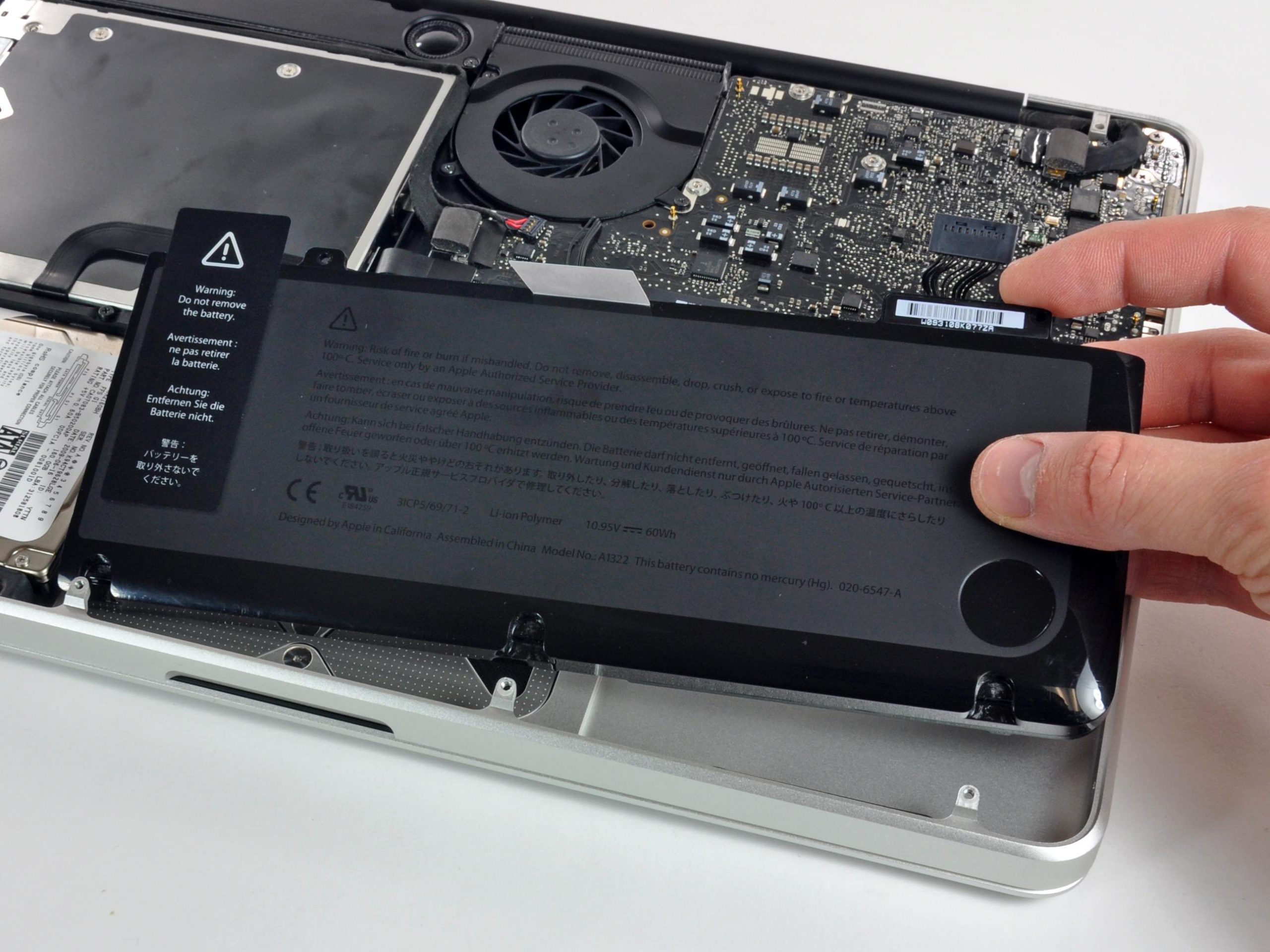
Just a heads-up, it’s a smart move to unplug the battery connector from the logic board to dodge any surprise zaps.
– Grab the flat end of your spudger and give the battery connector a gentle nudge out of its socket on the logic board.
Tools Used

Step 4


– Grab your trusty spudger and give the fan connector a gentle nudge out of its cozy home, then lift it straight up off the logic board like you’re pulling a rabbit out of a hat!
Hey there! Ready to dive into your device? Check out the second and third pics to spot the fan socket and connector. Remember, gently does it—use your spudger to ease the fan connector up and out without snapping the plastic socket on the logic board. Your board might look a tad different than the one in the pic, but no worries, the fan socket’s the same. Happy fixing!
Tools Used
Step 5

– Unscrew the trio of screws that are holding the fan to the upper case:
Step 6

– Hoist that fan right out of the upper case like you’re lifting a trophy!
Step 7


– Alright, start by grabbing that handy plastic pull tab attached to the display data cable lock and swirl it towards the DC-in side of your trusty machine.
– Now, give the display data cable connector a firm pull straight out from its cozy socket, aiming towards the DC-in side. If you need help, you can always schedule a repair.
Step 8


– Whip out your screwdriver and unscrew the two screws that are keeping the display data cable bracket tied down to the upper case.
– Gently lift the display data cable bracket out of the upper case and set it aside.
Step 9

– Grab the flat end of your spudger and gently lift the subwoofer and right speaker connector off the logic board. You got this!
Tools Used
Step 10

– Gently tug the camera cable connector towards the optical drive to gracefully release it from the logic board.
Alright, it’s showtime for the camera cable! Most gadgets sport a nifty little plastic retainer glued to the logic board, just to keep that connector from party-crashing. Make sure to slide that sneaky retainer out of the way before you go disconnecting anything. Ready, set, go!
Keep an eye on that shiny metal socket—it’s a tricky little critter and bends easily. Make sure the connector and its socket on the logic board are having a perfect alignment before you click them together.
Step 11


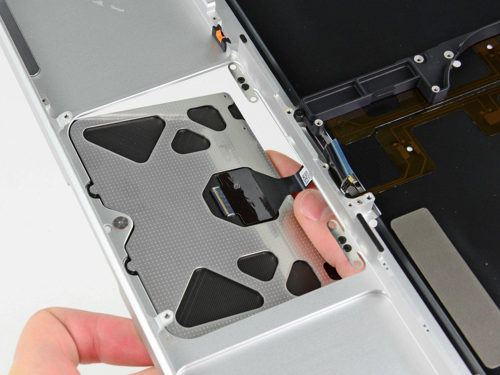
– Grab your spudger and carefully pop the connectors for the optical drive, hard drive, and trackpad cable right off the logic board. If you need help, you can always schedule a repair.
Tools Used
Step 12


– Pop that cable retaining flap open with your fingernail or the tip of a spudger—think of it like lifting the lid on a treasure chest, but for the keyboard ribbon cable.
– Gently slide that keyboard ribbon cable out of its cozy socket with your spudger. It’s like pulling a card out of a magic trick hat!
Tools Used
Step 13

– Get ready to uncover the keyboard backlight ribbon cable – gently lift that small strip of black tape off the socket like a pro!
Step 14


– Now, let’s rock and roll! Use the handy spudger to lift up the cable retaining flap on the ZIF socket for the keyboard backlight ribbon cable.
– Time to show off your skills! With finesse, glide the keyboard backlight ribbon cable out of its socket using the trusty spudger.
Tools Used
Step 15

– Gently slide the flat end of a spudger under the battery indicator cable connector and lift it off the logic board with care. You’ve got this!
Tools Used

Step 17

– Time to get those screws out! Let’s tackle the following screws:


Step 19


Watch out, party people! Make sure you don’t accidentally yank out that oh-so-delicate microphone connector. It’s a fragile little star, just like you!
– Gently lift the logic board by its left edge and raise it until the ports clear the upper case’s side. You’ve got this!
– Carefully pull the logic board away from the upper case and take it out, keeping an eye on the DC-in board that might try to tag along.
Step 20

– Gently pull the DC-In board’s connector away from the logic board’s socket to disconnect it. You’re doing great!