How to Replace MacBook Pro 15 Front Display Bezel
Duration: 45 minutes
Steps: 48 Steps
Heads up, tech warrior! Keep your eyes peeled and follow these steps to become a master in gadget repair. Remember, if things get tricky, you can always schedule a repair with Salvation Repair. Let’s make this device feel brand new!


Step 2


– First things first, let’s tackle those three matching 2mm Phillips screws hiding out by the memory door. Time to unscrew them and set them aside.
– Once the screws are out of the way, gently lift the memory door just enough to get a good grip. Now, slide it towards you, away from the casing, and voilà!
Step 3

– Time to get your screwdriver ready! Carefully take out those two 2.8 mm Phillips screws hanging out in the battery compartment by the latch. You’re doing great!
Step 4

– Unscrew those 6 little troublemakers!
Step 5

– Time to get your screwdriver ready! Unscrew those four 3.2 mm PH00 Phillips screws on the port side of your computer. You’ve got this!
Step 6

– Give your computer a cool spin (90 degrees to be exact) and whisk away those two 3.2 mm Phillips screws hanging out at the back. It’s screw-loosening time!
Step 7

– Give your computer a little twirl! Spin it 90 degrees one more time and whisk away those four 3.2 mm Phillips screws from the side. Keep grooving!
Step 8


Hold up, don’t just rip off the upper case like it’s a dance-off contest! Remember, it’s still shaking hands with the logic board via a ribbon cable.
– Start by lifting the back of the case, then wiggle your fingers along the sides to loosen it. Keep going until the sides are free, and you might need to give the case a gentle rock to unhook the front.
– There are five pesky plastic clips to tackle: four above the DVD slot and one more above and to the left of the IR sensor. These clips are notorious for being stubborn, so you might need to pry a bit to get them out and be patient when snapping them back in during reassembly.
– Reassembly Tip: To make sure each clip is securely in place, press down hard over each clip location until you hear a satisfying snap, confirming they’re locked in.
– Reassembly Tip: Those two middle DVD clips are a bit tricky and tend to not snap back easily, which can warp the frame around the DVD slot. To avoid this, place a plastic spudger in the DVD slot right under the clip to support the frame, then press down until it clicks into place.
Tools Used

Step 9


Heads up, tech adventurer! You can swap out that hard drive without having to detach the keyboard from the chassis. Just prop it up to keep it out of your way—this lets you have both hands free to work on ejecting that drive.
Watch out for that sneaky keyboard-trackpad ribbon cable while you’re at it! Make sure the back end of the upper case is free from the hinge area. It’s a breeze to accidentally warp the screw receivers flanking the keyboard.
– Gently unplug the trackpad and keyboard ribbon cable from the logic board, and feel free to peel away any tape that’s in the way.
– Carefully take off the upper case.
Step 10

– Unplug those pesky antenna cables from the Airport Extreme card. You might find two or three of them, depending on the model you’re working with. If there’s a third one just hanging out with a black shrink tube, it’s just taking a little nap and doesn’t need to be connected.
– Big shoutout to Apple for the handy color-coded label right on the card! It’s a real lifesaver when you’re plugging the cables back in. Just take a peek at that label to see where each colorful cable should go.
Step 11

– Unwind those Airport antenna cables from their hangout in the left speaker’s channel. Who knew cables could be such social butterflies, right?
Step 12

– Slide the iSight cable to the left and gently wiggle it out of its connector on the logic board. It’s like pulling a card from a deck—smooth and easy!
Step 13

– Hold the display steady with one hand while you take out the screws listed below:
Step 14

– Gently unhook the inverter cable from the left I/O board by sliding a spudger under the cable and giving it a little lift. You’ve got this!
Tools Used
Step 15


– Unplug the display data cable from the motherboard like a boss. Easy-peasy!
– Peel off the foam bumper from the top of the right hinge on the display—like removing a band-aid!
Step 16

– Unscrew the shiny 9.2 mm T6 Torx that’s holding the ground loop of the display data cable to the casing. It’s like unscrewing the secret to your device’s happiness!
Step 17

– Hold the screen steady with one hand while you unscrew the following screw:
Step 18

– Grab the display assembly on each side and gently lift it out of the computer. You’ve got this!
Step 19


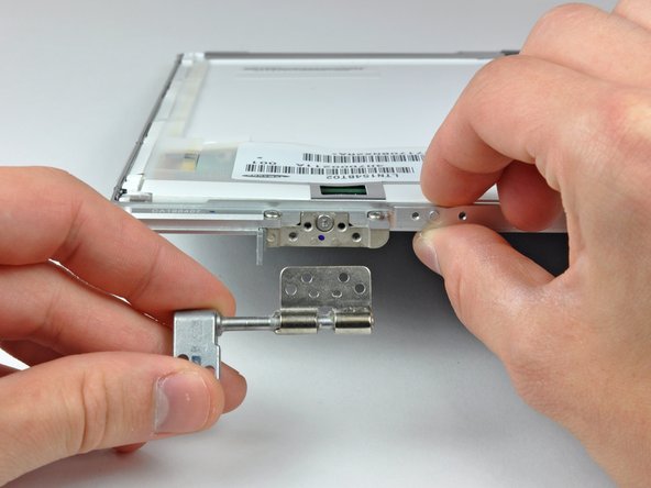
– Time to get those screws out! Grab your trusty Phillips screwdriver and remove the two 4.5 mm screws from the lower left and right corners of the display. Just a heads up, these little guys have a .8 mm thick head, so make sure your tool fits snugly. You’ve got this!
Step 20


Hey there! Just a friendly reminder: keep that spudger away from the plastic strip and rear bezel. We want to keep everything safe and sound!
– Pop that spudger in at a right angle to the display, sliding it in between the plastic strip that’s cozy with the rear bezel and the front bezel.
– With the spudger still in its happy spot, give it a little twist away from the display. This will help you break up the bond between the front and rear bezels.
– Keep working your way along the right edge of the display until the rear bezel and front bezel are nicely separated and free to breathe.
Tools Used
Step 21


– Gently slide your spudger into the gap between the front and back display bezels, starting at the lower right corner of the display. You’re on your way!
– Carefully pry the rear bezel away from the front bezel just enough to create a little wiggle room at the bottom edge. You’re doing great!
Tools Used
Step 22


– Place the flat end of a spudger into the gap between the rear display bezel and the clutch cover.
– Rotate the spudger to disengage the lower edge of the rear display bezel from the clutch cover.
– Continue along the lower edge of the rear bezel, ensuring it is uniformly separated from the clutch cover.
Tools Used


Step 24


– Wedge the flat end of a spudger between the front bezel and the plastic strip on the rear bezel near the screw holes at the bottom corners of the display. It’s like sneaking into a cookie jar!
– Twist your spudger toward the rear bezel like you’re turning a key to unlock some tech treasure. This will help separate it from the front bezel.
– If needed, keep on prying the left edge of the rear bezel away from the tabs on the front display bezel. You’re doing great—keep the momentum going!
Tools Used
Step 25

– Gently elevate the lower edge of the display and slide it out from the rear display bezel like you’re performing a magic trick.
– Need more wizardry? Wave your wand over to the guide for continuing the screen replacement adventure: MacBook Pro 15″ Core 2 Duo Models A1226 and A1260 LCD Panel Replacement
Step 26

– Gently nudge the LED driver board out of the clutch cover using the tip of a spudger. You’ve got this!
Tools Used
Step 27

– Give that backlight cable a little tug to disconnect it from the socket on the LED driver board.
Step 28

Hey, take it easy on that LED driver cable ground loop! It’s super thin and delicate, and it snaps in a heartbeat if you pull too hard.
– Gently wiggle the LED driver cable and give it a little pull to disconnect the connector from the inverter board socket. No need to be rough here!
– Carefully lift the LED driver board out and place it somewhere safe for now. You’re doing great!
Step 29


– Hey there! Let’s kick things off by peeling off those two pieces of kapton tape that are kindly covering up the display data cable.
– Next, let’s tackle that strip of tape keeping the iSight cable snug against the LCD. Peel it off gently.
– Finally, it’s time to free those three antenna straps from the lower edge of the LCD. Off they go!

Step 31

– Unscrew those two Phillips screws holding down the ground straps for the display data cable and the LED driver board cable to the clutch cover. You’ve got this!
Step 32

– Unscrew the sneaky Phillips screw that’s hiding behind the display data cable.
Step 33

– Unscrew those three Phillips screws hiding behind the antenna straps at the bottom edge of your display. You’ve got this!
Step 34

– To kick off the removal of the clutch assembly, slide the flat end of your trusty spudger into the little gap between the clutch hinge and the clutch cover where those cables make their grand exit.
– As you gently pry the clutch assembly away from the hinge with your spudger, grab a plastic opening tool to help widen the gap between the clutch cover and the front display bezel. Teamwork makes the dream work!
– Keep moving along the length of the clutch cover to completely break free that adhesive. You’re doing great!
Tools Used
Step 35

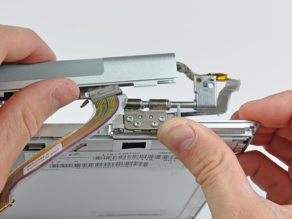
– Gently nudge the clutch assembly away from each of the clutch hinges and lift it off the display. You’ve got this!
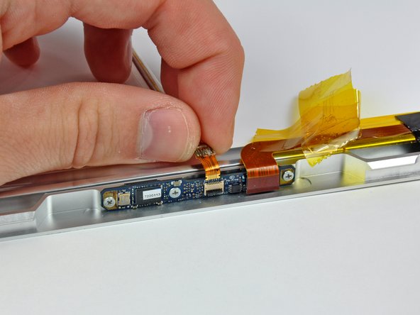
Step 36

Gently press down on the iSight cable while you carefully peel back the tape. No need to go all out and remove the tape completely!
– Go ahead and gently peel away those pieces of tape that are keeping the iSight cable safe and sound.
Step 37
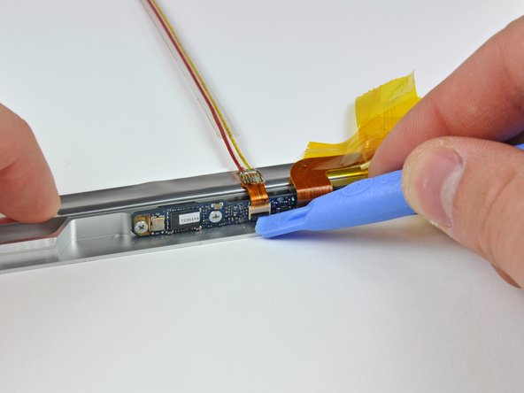

– Grab your trusty plastic opening tool and gently lift the ZIF cable lock. It’s like a little dance move for your device!
– Now, slide that iSight cable out of its cozy socket. It’s time for it to come out and play!
Step 38

– Disconnect the iSight cable from the display.


Step 41

– Gently guide the display data cable away from the right clutch hinge and put it in a safe spot.

Step 43
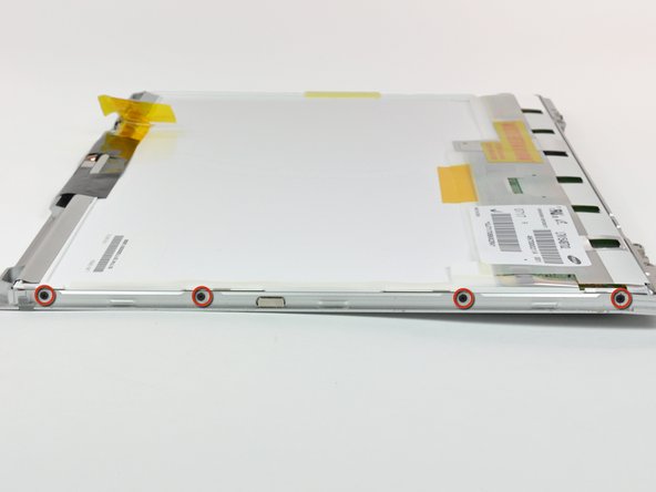

– Unscrew those four Phillips screws on each side of the display—yep, that’s eight screws in total! You’ve got this!
Step 44
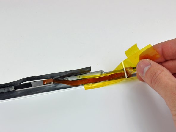

No need to go all out and take off this piece of tape completely!
– Gently peel away the big piece of tape that’s hanging out near the display latch at the top edge of the LCD.
– Carefully take off the bits of tape that are keeping the camera ribbon cable snug against the display.
Step 45

– Get the party started by using the flat end of a spudger to gently lift one of the top corners of the LCD out of the front bezel.
Heads up! The adhesive is super clingy and it hugs a sleek steel strip around the edge of the LCD. Make sure you’re gently separating the front panel from this steel strip on the LCD, not just yanking them apart!
Tools Used

Step 47

– Now that you’ve gracefully freed the top edge, gently lift the LCD out of the front bezel to create enough space to delicately pry the steel strip along the lower edge of the LCD away from the front bezel.
– Carefully pry along the lower edge of the LCD until it effortlessly releases from the adhesive on the front bezel.