
DIY MacBook Pro 15 Battery Connector Replacement Guide
Duration: 45 minutes
Steps: 24 Steps
Heads up, tech whiz! Make sure you’re in a well-lit area and have all your tools ready to rock. Let’s get this device back in action!
Time to juice up that battery and get it cozy with the logic board!


Step 2


– Unscrew the trio of 2mm Phillips screws securing the memory door. They’re all twinsies, so keep track of them!
– Give the memory door a gentle lift and tug it towards you to slide it off. It’s like pulling a tray out from the party mix!
Step 3

– Unscrew the two 2.8 mm Phillips head party poopers chilling near the latch in the battery hideout.
Step 4

– Unscrew the following 6 screws:
Step 5

– Unscrew the four 3.2 mm PH00 Phillips screws on the port side of the device. Let’s keep those tiny dancers safe and sound for reassembly!
Step 6

– Give your computer a little twist and turn it 90 degrees! Now, let’s get those two 3.2 mm Phillips screws out from the back. You’ve got this!
Step 7

– Give your computer a little twist and turn it 90 degrees once more. Now, let’s tackle those four 3.2 mm Phillips screws hanging out on the side. Time to show them who’s boss!
Step 8


Gently detach the upper case as it is connected to the logic board through a delicate ribbon cable.
– Start by lifting from the back of the case and wiggle your fingers along the edges to loosen it up. Keep going until the sides are free. You might need to give the case a little rock and roll to unhook the front.
– Watch out for four sneaky plastic clips above the DVD slot, plus one more above and to the left of the IR sensor. These clips are a bit of a tricky business to pop out without a bit of prying, and they can be just as stubborn when you’re putting everything back together.
– Reassembly Tip: Give a good firm press right above each clip until you hear a satisfying snap to make sure they’re snug back in their homes.
– Reassembly Tip: Those two middle DVD clips can be real drama queens and might not snap back easily. To keep the frame from bending, slip a plastic spudger into the DVD slot right under the clip’s spot. Push down steadily until you hear that victorious snap.
Tools Used

Step 9


Heads up! You can swap out the hard drive without taking the keyboard off the chassis. Just prop it up carefully—it’s like a balancing act, letting you free up both hands to work on the drive!
Watch out when you disconnect the keyboard-trackpad ribbon cable. Make sure the back of the upper case is clear from the hinge area. It’s super easy to accidentally warp the screw receivers at the sides of the keyboard.
– Unplug the trackpad and keyboard ribbon cable from the logic board, peeling off any tape that gets in your way.
– Gently lift off the upper case and set it aside.
Step 10

– Grab the flat end of your spudger and gently disconnect the zesty orange SuperDrive ribbon cable from the logic board. Peel off any tape that’s cramping your style along the way.
Tools Used
Step 11
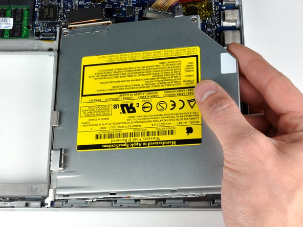

– Take out these 4 funky screws:
– Hoist the optical drive out of its cozy nook like a magician pulling a rabbit out of a hat!
Step 12

– Unplug the hard drive and ExpressCard connectors on the left side of the logic board. Easy peasy!
Step 13

– Slide the iSight and display data cables right out of their homes on the logic board. Just tug them straight back, and peel off any tape that gets in your way. You’ve got this!
Step 14

Be gentle when you’re unplugging those tiny connectors! A heavy-handed spudger move might just snap them off the logic board. Handle with care, like you would a fragile treasure!
– Get ready to party with your device! Use a spudger to gently disconnect the eight connectors by sliding it underneath the wired side of each connector and giving it a little lift. Time to groove and get those connectors dancing!
Tools Used
Step 15

– Gently peel off the foam bumper that’s snugly resting on the top of the right hinge of your display. It’s like giving your device a little spa treatment!
Step 16

– Time to get groovy with your tools! Grab your trusty T6 Torx screwdriver and spin out that shiny 9.5 mm silver screw that’s holding the ground loop of the display data cable to the case. You got this! And hey, if things get tricky, you can always schedule a repair.
Step 17

– Unscrew the cool black 6 mm T6 Torx screw that’s keeping the upper part of the logic board attached to the lower case. You got this!
Step 18

– Gently lift the orange Kapton tape that’s keeping the right thermal sensor cable cozy on the logic board.
Step 19

– Alright, let’s dive in and unscrew the following 15 screws:
Step 20

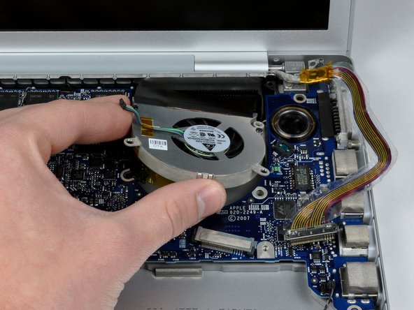
– Keep a steady hand on the logic board and use your free hand to gently lift the left fan out of its cozy spot. Oh, and there’s a sneaky piece of black tape clinging to the left fan and heat sink. Carefully unstick that tape as you lift the fan.
– Time to give the right fan some freedom! Lift it up and peel away the tape that’s hugging it to the heat sink along the way.
– Wave goodbye to the right fan as you remove it from the computer.
Step 21


– Gently hoist the left side of the logic board and unplug the snazzy gray and black power cable nestled at the board’s base.
– Get a good grip on the left and the slender section of the logic board, then smoothly swivel it out of the lower case—like you’re doing a tech dance move!
– If you gave the heatsink a break from the motherboard a couple of steps back, it’s spa time! Scrub off that old thermal goop from the chips on the logic board’s flip side. Check out our groovy Applying Thermal Paste Guide to get the processor and heatsink ready for action.

Step 23

– Unplug the snazzy large gray and black battery connector cable from the left I/O board, like a boss!
Step 24

– Sneak the gray and black power cable under the speaker cable, then gently hoist the battery connector out of the computer like you’re lifting a tiny crown. Nice and easy!


