How to Replace MacBook Pro 15 Antenna Cables Guide
Duration: 45 minutes
Steps: 39 Steps
Heads up, tech whiz! Make sure to handle your device with care and keep those tools at the ready. Remember, you’re just a few steps away from having your gadget back in tip-top shape. If you hit a snag, don’t sweat it—help is just a click away at schedule a repair. Let’s make this repair a smashing success!
Hey there tech wizard! Ready to swap out those AirPort/Bluetooth antenna cables on your MacBook? This guide’s got your back with all the steps you need. If you need help, you can always schedule a repair. Let’s get those cables singing a new tune!


Step 2


– Unscrew the trio of snazzy 2mm Phillips screws holding down the memory door. Easy peasy!
– Give that memory door a gentle lift and a smooth slide towards you to free it from its cozy casing.
Step 3

– Now, jump into action by unscrewing the two 2.8 mm Phillips screws snugly resting in the battery compartment near the latch.
Step 4

– Unscrew those 6 little screws like a pro!
Step 5

– Unscrew the four 3.2 mm PH00 Phillips screws on the port side of your device. Let’s turn those screws!
Step 6

– Give your computer a little twist and turn it 90 degrees! Now, let’s unscrew those two 3.2 mm Phillips screws at the back. You’ve got this!
Step 7

– Give your computer a cool 90-degree spin and whisk away those four 3.2 mm Phillips screws from the side. Keep the groove going!
Step 8


Hold your horses! Don’t just rip the upper case off like it’s a band-aid. There’s a sneaky ribbon cable connecting it to the logic board. Ease it off gently, like you’re coaxing a cat out from under the bed.
– Start by lifting the back of the case and wiggle your fingers along the edges to loosen it. Keep going until the sides are free, then gently rock the case back and forth to detach the front of the upper case.
– There are four stubborn plastic clips above the DVD slot and another tricky one above and to the left of the IR sensor. These clips might give you a hard time if you don’t pry them. Putting them back during reassembly can be just as challenging.
– Reassembly Tip: Give a solid press on the top case directly above each clip until you hear a satisfying snap to make sure they’re securely in place.
– Reassembly Tip: The two middle DVD clips are a bit rebellious and don’t usually snap back into place without a little extra help. To prevent the frame from bending, slide a plastic spudger into the DVD slot right under the clip location until it feels tight, then press down until you hear that delightful snap.
Tools Used

Step 9


Heads up! You can totally swap out the hard drive without having to remove the keyboard from the chassis. Just prop it up vertically, and voilà, you’ve got your hands free to work on yanking that drive!
Watch out for that sneaky keyboard-trackpad ribbon cable when you’re freeing up the rear of the upper case near the hinge. It’s a breeze to accidentally tweak the screw receivers flanking the keyboard, so let’s keep things smooth and bend-free!
– Unplug the trackpad and keyboard ribbon cables from the logic board, peeling off any tape that gets in your way.
– Lift off the upper case with a flourish.
Step 10

– Unplug the two or three antenna cables from the Airport Extreme card. If you find a third one just hanging there with a cool black shrink tube, it’s just chilling unused.
– Props to Apple for the handy color-coding label on the card—super helpful! Make sure to peek at that when you’re hooking the antenna cables back up.
Step 11

– Wiggle those Airport antenna cables out of their cozy channel in the left speaker!
Step 12

– Slide the iSight cable to the left and gently pull it out of its connector on the logic board. Easy peasy!
Step 13

– Give that display a little love and support it with one hand while you unscrew those screws like a pro!
Step 14

– Use a spudger to gently lift the inverter cable off the left I/O board. Just slide the spudger underneath and give it a little nudge upwards. Easy-peasy!
Tools Used
Step 15


– Unplug the display data cable from the logic board like a boss.
– Peel off the foam bumper from atop the right hinge of the display with a flourish.
Step 16

– Unscrew the shiny 9.2 mm T6 Torx to liberate the ground loop from its ties to the display data cable and the casing. Freedom!
Step 17

– Hold the screen up with one hand while you unscrew the following screw:
Step 18

– Grab each side of the display assembly and gently lift it up and away from the computer. You’re doing great!
Step 19


– Unscrew the two 4.5 mm Phillips screws chilling in the lower left and right corners of the display. They’re sporting a .8 mm thick head. Just a heads up!
Step 20


Keep your spudger away from the sneaky gap between the plastic strip and the rear bezel!
– Pop the flat end of a spudger in like a pro, right between that sneaky plastic strip on the rear bezel and the front bezel. Make sure it’s perpendicular to the face of the display, just like you’re slicing a piece of cake!
– Keep that spudger in place, and give it a little twist away from the display. It’s like opening a jar of pickles during halftime—just a bit of elbow grease and you’re in!
– Slide along the right edge of the display, and keep going until the rear bezel and the front bezel are partying separately. You’re almost there, champ!
Tools Used


Step 22


– Slide the flat end of your trusty spudger into the little gap between the rear display bezel and the clutch cover.
– Give that spudger a gentle twist to pop the lower edge of the rear display bezel away from the clutch cover.
– Keep working your way along the lower edge of the rear bezel until it’s all nicely separated from the clutch cover.
Tools Used


Step 24


– Gently slide the flat end of a spudger between the front frame and the plastic strip that’s attached to the back frame near the screw holes at the bottom corners of the screen.
– Give your spudger a little twist towards the back frame to start separating it from the front frame.
– If needed, keep working along the left edge to pop the back frame free from the tabs on the front display frame.
Tools Used
Step 25

Step 26

– Grab your spudger and gently lift the LED driver board out of the clutch cover like a pro. You’ve got this!
Tools Used
Step 27

– Unplug the backlight cable by gently sliding its connector out from the socket on the LED driver board. Easy-peasy!
Step 28

Take it easy on the LED driver cable ground loop! It’s super skinny and super delicate, so let’s not break it by getting all Hulk on it!
– Unplug the LED driver cable by gently tugging its connector from the socket on the inverter board. Easy does it!
– Take the LED driver board off and pop it to the side. We’ll get back to that little guy soon!
Step 29


– Whisk away those two sneaky pieces of kapton tape hiding on the display data cable.
– Unstick that cheeky strip of tape that’s keeping the iSight cable too cozy with the LCD.
– Gently peel off the trio of antenna straps clinging to the lower edge of the LCD like little limpets.

Step 31

– Unscrew the two Phillips screws holding down the ground straps for both the display data cable and the LED driver board cable to the clutch cover. Let’s keep those cables snug and secure!
Step 32

– Unscrew the sneaky little Phillips screw that’s playing hide and seek behind the display data cable. Gotcha!
Step 33

– Unscrew the trio of Phillips screws hiding behind the antenna straps at the bottom of the display. It’s like a tiny treasure hunt!
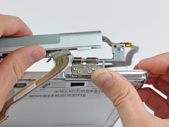
Step 34

– Start off by wedging the flat end of a spudger into the nook where the clutch hinge and the clutch cover kiss goodbye, right where the cables make their grand exit.
– Keep easing the clutch assembly off the clutch hinge with your trusty spudger while simultaneously using a plastic opening tool to widen the love gap between the clutch cover and the front display bezel.
– Saunter your way down the length of the clutch cover to completely detach the sticky situation with the adhesive.
Tools Used
Step 35

– Slide the clutch assembly off each of the hinges with a gentle push and whisk it away from the display. Voila! You’re doing great.
Step 36

– Unscrew the five sassy little Phillips screws that are playing hide and seek under the plastic antenna cover inside the clutch cover. Let’s free them from their tight spots!
Step 37

– Gently slide off the antenna cover from the clutch cover, and watch out for those sneaky antenna cables!
Step 38

– If you need to, gently peel the antenna leads from the sticky adhesive that’s keeping them stuck to the clutch cover. It’s like peeling a banana!
– Carefully remove the antenna cables from the clutch cover. Watch out for the three antenna straps—treat them like delicate spaghetti!
Step 39

– Gently wiggle the antenna cables free from the clutch cover. Keep an eye on those three antenna straps — we wouldn’t want them to feel left out and get damaged!


