DIY Guide: Mini Digital Oscilloscope Soldering Skills Assembly
Duration: 45 minutes
Steps: 64 Steps
Heads up! Make sure you’re working in a well-lit space and have all your tools ready to go. If you hit a snag, don’t sweat it! If you need help, you can always schedule a repair.
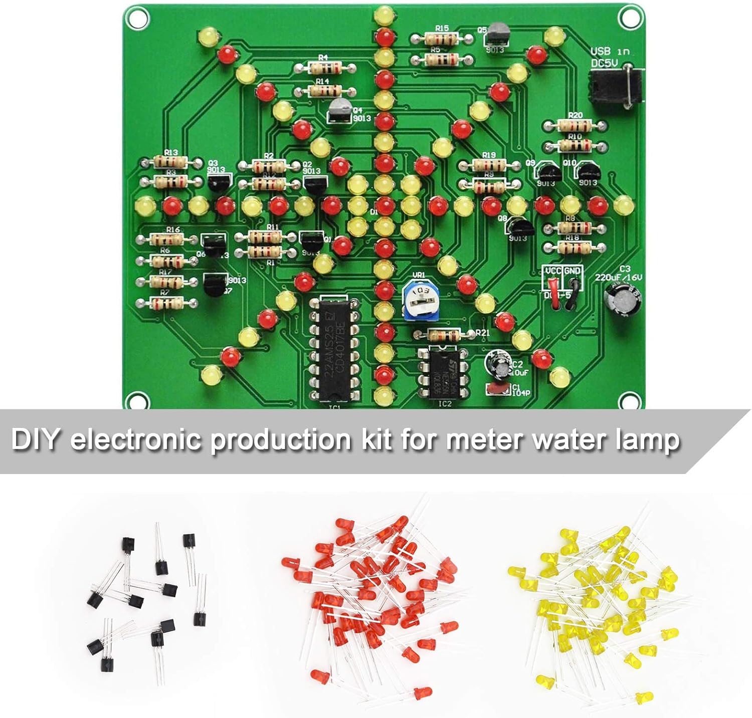
Get ready to create your very own portable oscilloscope with the Mini Digital Oscilloscope DIY Soldering Kit! This kit is perfect for those looking to level up their surface-mount soldering game, but it’s not really meant for newbies. If you’re just starting out with soldering, we suggest kicking things off with a more beginner-friendly kit. And if you want to brush up on your soldering skills before you dive in, check out our guide on soldering and desoldering connections. Happy soldering!
Step 1


– If you’re tackling this indoors, make sure to set your fume extractor right next to your workspace. Arrange your tools in a bright area, keeping them clear of anything that could catch fire. Safety first, right?
Step 2

– Here’s what your oscilloscope kit comes packed with:
Step 3
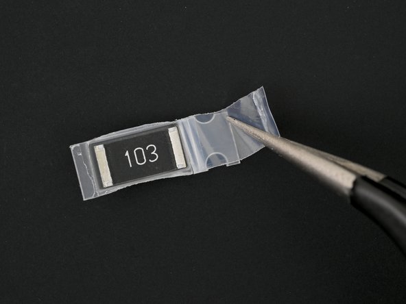

Each resistor and capacitor (except for the three 2 kΩ resistors) has its own special spot on the board, so make sure to install them correctly! The 10 μF and 22 nF capacitors may look like twins from their packaging labeled 103, but don’t let that fool you. Grab some tweezers to delicately peel off each component’s packaging before you start soldering. You got this!
– Grab an LED, it’s going to light up your project!
– Next, you’ll want a 1W/10 kΩ (103) resistor to keep things in check.
– Don’t forget another 10 kΩ (103) resistor to balance everything out.
– Now, let’s add two 2 kΩ (202) resistors for some extra support.
– A 10 μF capacitor is up next to help smooth things over.
– You’ll also need a 10 nF (103) capacitor to keep the vibes just right.
– Last but not least, grab a 22 nF capacitor to wrap things up nicely.
Step 4

– Place the circuit board on your work mat or surface with the front side (the one marked MiNi-DSO at the top) facing up, ready for action!
Step 5


– Time to gear up! Slip on those safety glasses to keep your peepers protected.
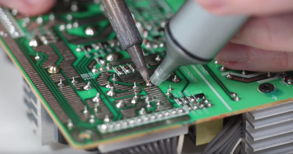
– Fire up your soldering iron! If it has temperature control, make sure it’s set just right.
– Let’s keep that tip clean! If you’re using a cellulose sponge, give it a little splash of distilled water until it’s damp, then quickly wipe the tip across it. If you’ve got brass wool, just give it a few friendly stabs with the tip.
– Now, let’s tin that tip! Melt a tiny blob of solder on it. This little trick helps heat transfer like a champ.
Step 6


In this step, we’re going to get one of the resistor’s pads on the board all set up with a little solder magic. This will make it a breeze to attach the resistor when the time comes!
– Gently press the tip of the iron onto one of the solder pads in the R4 outline for a few seconds to get it nice and warm.
– Next, introduce the solder wire to the cozy heated spot until you see a little blob of solder forming on the pad.
– Once that’s done, pull the solder wire away first, then lift the soldering iron off the pad. Easy peasy!
Step 7


– Grab that big 10 kΩ resistor (you’ll spot it by the label 103) and pop it right into the R4 outline on the board.
– Heat up that solder again while gently holding the resistor in place, letting the molten solder wrap around the shiny end cap like a cozy blanket.
– Once the solder cools down, take away the iron and then the tweezers. You’re all set!
Step 8


In this step, we’re going to warm up the solder pad and the end cap of the resistor so that they’re ready to embrace the solder wire like old friends.
– Gently press the tip of your soldering iron against the second R4 solder pad and the second end cap of the resistor for a few seconds to warm them up. Make sure to angle the tip for the best contact with both the pad and the cap.
– Now, bring in the solder wire and feed it into the warmed area until you see a little blob of solder forming around the end cap. It’s like giving it a cozy blanket!
– Once you’ve got that little glob of goodness, carefully pull away the solder wire first, then lift the soldering iron from the pad. Easy peasy!
Step 9

Awesome job! You’ve successfully soldered that resistor onto the board!
If you notice one of the solder joints isn’t quite connecting with an end cap, no worries! Just reheat that cap and add a little more solder. If the solder isn’t flowing smoothly, a touch of flux will help it along before you add more.
Keep an eye out for any sneaky solder bridges that might have formed between pads. If you spot one, gently heat the solder with your iron and separate the bridge. If it’s being stubborn, don’t hesitate to desolder it and give it another go!
Step 10


– Gently place the tip of the iron onto one of the R2 solder pads on the board and let it hang out there for a few seconds to soak up some heat.
– Once it’s nice and warm, introduce the solder wire to the cozy spot until you see a small puddle of solder forming on the pad.
Step 11
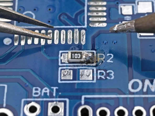

– Grab that smaller 10 kΩ resistor (you’ll find it labeled 103) and pop it into the outline marked R2 on the board.
– Now, gently press the tip of your soldering iron onto the edge of the solder pad while keeping the resistor snug in its spot. Make sure the end caps (those shiny bits) are cozy on the circuit board’s pads.
– Once you’re done, carefully lift the iron away, and after a moment for the solder to chill, you can remove the tweezers.
Step 12


– Gently press the tip against the second R2 solder pad and the second end cap of the resistor for a few seconds to warm them up together. Try to angle the tip for the best contact—let’s make that connection count!
– Now, bring in the solder wire and feed it into the cozy, heated area until you see a nice little blob of solder forming around that second end cap. You’ve got this!
Step 13


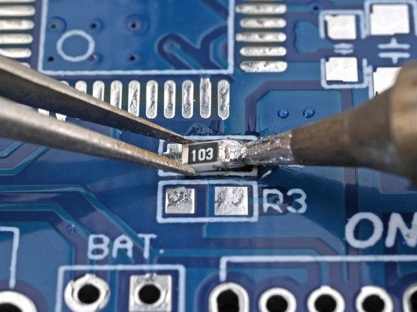
– Go ahead and repeat the process to solder the three 2 kΩ resistors (marked 202) into the spots labeled R3, R1, and R5 on the front of the board. You’ve got this!
Step 14


– Go ahead and repeat the magic! Solder those three capacitors onto the front of the board, just like before!
Step 15


– Gently press the tip of your iron onto the LED solder pad on the circuit board for a few seconds to warm it up, then introduce the solder wire to the cozy heated spot until you see a delightful little blob of solder form on the pad.
– Carefully position the LED in the designated LED outline on the board, ensuring that the non-green side aligns perfectly with the ‘+’ symbol.
– Secure the LED’s first end cap to the board with a bit of soldering magic.
Step 16


– Gently place the tip on the second LED solder pad and let the solder wire flow into the warm area until you see a little blob of solder making friends with the end cap.
– Once you’ve got that glob just right, pull away the solder wire first, and then gracefully lift the soldering iron off the pad.
Step 17

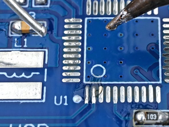
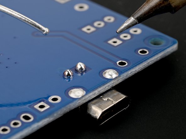
Now, let’s get that solder flowing on one of the microcontroller pads! This little trick will keep everything lined up perfectly when you attach it to the board. You’ve got this!
– Gently place the tip of the iron on the bottom left microcontroller solder pad of the board and let it warm up for a few seconds. We’re getting cozy here!
– Now, introduce the solder wire to the warmed-up area and let it melt into a lovely little blob on the pad. Perfecto!
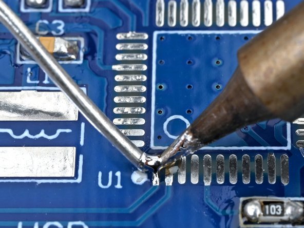
Step 18


– Go ahead and give that last step another go to add some solder to the top right microcontroller solder pad on the board. You’ve got this!
Step 19


– Get that microcontroller in position! Line it up with its outline (that’s U1, in case you forgot) on the circuit board, making sure the circle on the microcontroller is right on top of the circle on the board.
– Now, let’s make sure all 44 pins are perfectly aligned with their cozy little pads on the board.
– Keep that microcontroller steady with some tweezers magic and give a little re-heat to the solder from the last steps to secure it to the board. You’ve got this!
Step 20

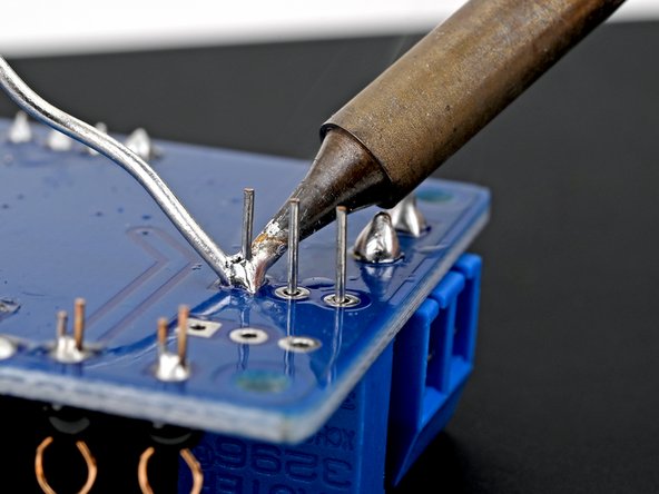
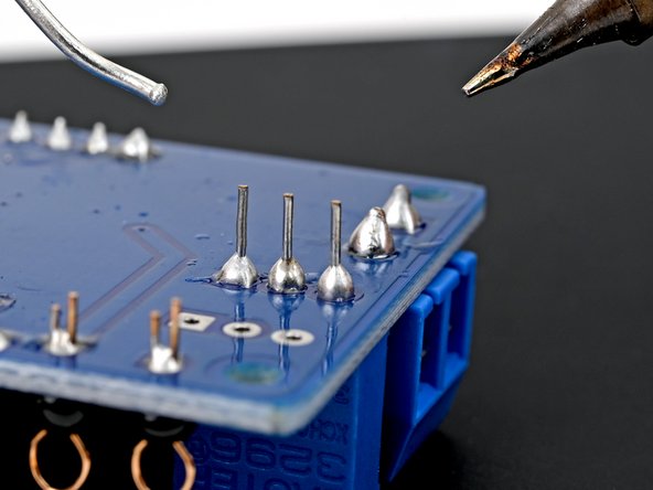
This task can be a bit tricky and may take some time. So, take a deep breath and proceed with caution to avoid overheating those solder pads or pins! And remember, desoldering wick is not your friend here – it could wreak havoc on the pads. Just take it slow and steady!
– Gently touch the tip to another solder pad and let the solder wire flow into the warm area until you’ve got a nice little solder joint on the pin.
– Keep it going and repeat this for all the other microcontroller pins!
Step 21


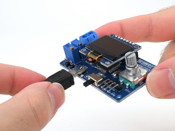
– Get that USB port lined up perfectly with the USB outline on the front of the board. It’s like a little puzzle piece waiting to fit in just right!
– Now, gently slide the leads of the USB port into their four cozy holes on the board, making sure it sits flush and snug. You’re doing great!
Step 22
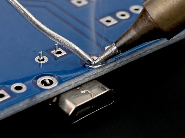

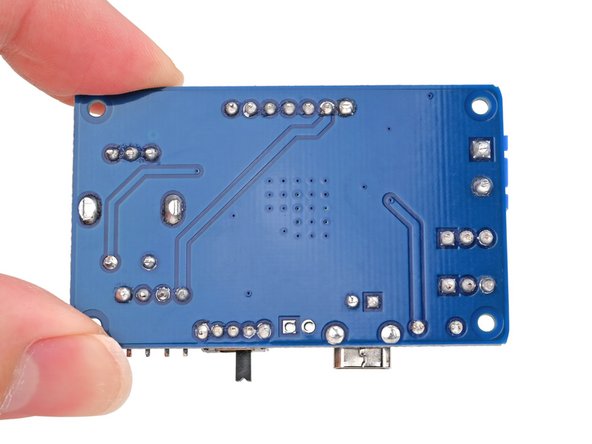
– First things first, flip that board over so the pins are waving up at you! It’s like they’re saying, ‘Hello!’
– Now, take the tip of your iron and gently press down on the solder pad of the USB port that’s closest to the edge. Let’s get that first pin all snug and secure!
– Once you’ve nailed that first pin, go ahead and solder the rest of the USB port pins. You’re doing great!
Step 23


– Let’s get those UART connector vibes going! Position the UART connector so that it matches up with the outline marked UART on the front of the board.
– Now, gently slide the shorter pins of the UART connector into their four designated holes on the board, ensuring it sits nice and flush.
Step 24


– Turn the board over so the pins are looking up at you. They’re ready for action!
– Attach the UART connector to the board with some soldering magic.
Step 25


– Gently press the tip of the iron against the L1 solder pad on the circuit board for a few seconds to warm it up, then add some solder wire to the hot spot until you see a little puddle of solder form on the pad.
– While keeping the inductor in place, give the solder a little more heat. Make sure the end caps (the ones with the notches) are snugly resting on the pads of the circuit board.
– Once the solder has cooled down, carefully lift the iron away and then remove the tweezers. You’re doing great!
Step 26


– Gently press the tip against the second solder pad of the power inductor and the second end cap. Hold it there for a few seconds to warm them up nicely. Make sure the tip is angled just right for the best contact with both the pad and the cap.
– Now, feed that solder wire into the warm spot until you see a little blob of solder connecting the second end cap to its pad. You’re doing great!
Step 27


– Grab those tweezers and gently pick up one of the test rings, giving its leads a little squeeze to keep them together.
– Now, pop those test ring leads into the hole marked PWM on the front of the board and get ready to rock!
Step 28


– Give it another go with the other test ring in the hole marked SIN.
Step 29


– Give the board a little flip so the test rings’ leads are waving at you from the top side.
– Now, let’s get those test rings cozy with the board by soldering them together.
Step 30


– Get that toggle switch all lined up with the ON outline on the front of the board, making sure the switch is facing out like it’s ready to party.
– Now, gently pop those five pins of the switch into their cozy little holes on the board. They’re just waiting to connect!
Step 31


– Turn the board upside down so the pins of the toggle switch are pointing up.
– Attach the toggle switch to the board with some soldering magic.
Step 32


– Carefully line up the OLED female header strip with the OLED outline on the board like a pro.
– Gently push the seven pins of the header into their designated holes on the board.
Step 33


– Turn the board over so the pins of the header strip are looking up at you.
– Go ahead and solder that female header strip onto the board!
Step 34


– Let’s get that terminal block lined up with the INPUT outline on the front of the board, making sure the terminal interface is facing out like it’s ready to party.
– Now, gently slide those two pins of the block into their cozy little homes on the board.
Step 35


– Turn the board over so those terminal block pins are pointing up, ready for action!
– Now, let’s get that terminal block soldered onto the board and make it stick like glue!
Step 36


– Let’s get that first adjustable resistor, the one tagged W204 up top, lined up with the RP1 outline on the front of the board. Make sure the shiny gold knob is hanging out close to the microcontroller, okay?
– Now, gently guide the three pins of the resistor into their designated holes in the board. You’ve got this!
Step 37

– Give that board a little flip so the resistor’s pins are waving at you from the top side.
– Now, let’s get that first adjustable resistor cozy on the board with some solder!
Step 38


– Get that second adjustable resistor (it’s the one marked W501 on top) lined up with the outline that says RP2 on the front of the board. Make sure the shiny gold knob is nice and cozy next to the microcontroller.
– Now, pop those three pins of the resistor right into their designated holes on the board. You’re doing great!
Step 39


– Give the board a little flip so those resistor pins are waving at you from the top side!
– Now, let’s get that second adjustable resistor soldered onto the board like a pro.
Step 40


– Position the encoder knob so it lines up with the EC11 outline on the front of the board. Make sure the three leads at the top fit snugly into the three holes beneath the MiNi-DSO label.
– Gently slide the encoder’s seven pins into their designated holes on the board.
Step 41


– Turn the board upside down so the encoder’s pins are looking up at you. They’re ready for action!
– Now, let’s get that encoder knob snugly soldered onto the board. You’re doing great!
Step 42


Step 45

Before plugging in the oscilloscope, take a moment to do a quick visual check of your workspace. Make sure there are no solder joints that look like they might be having a party together or any incomplete ones that could cause a ruckus. This little inspection can save your components from a not-so-fun time.
– Plug in the oscilloscope to a power source using the handy Micro USB cable that comes with it. You’re one step closer to your repair adventure!


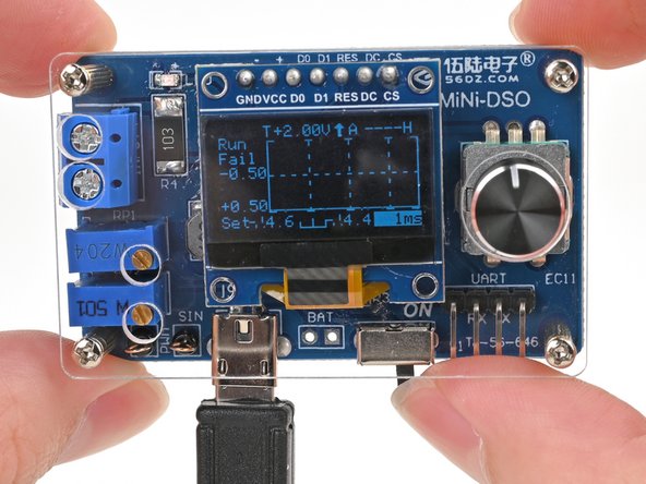
Step 47


– When your oscilloscope powers up, you’ll be greeted by a lively graph on the screen! Give that encoder knob a twist to make sure it’s working like a charm.
– After you’ve confirmed everything is running smoothly, go ahead and turn off the oscilloscope and unplug its USB cable. Easy peasy!
Step 48


– Grab your trusty flush cutters and give those test ring leads a little snip until they’re nice and flush with the solder joint from the back of the board. We want them to be as neat as a pin!
Step 49


– Just like before, go ahead and snip those leads down until they’re sitting nice and flush with the solder joint on the backside of the board. You’ve got this!
Step 50

Now’s the perfect moment to tidy up any leftover solder gunk. Grab some isopropyl alcohol and give those solder joints a little spritz, then wipe them down with a lint-free cloth to soak up the flux and any alcohol residue. Your device will thank you for the spa day!
Step 51

The next steps will guide you through putting together the oscilloscope’s case. Let’s get to it!
– The case is packed with these essential components:
Step 52


– Gently lift an edge of the bottom acrylic’s protective film using your fingernail or tweezers, and peel it off with care.
– Now, just repeat that same smooth move for the film on the opposite side.
Step 53


– Go ahead and give that top acrylic another round of love by peeling off the protective films. You’ve got this!
Step 54


– Pop one of those nifty 11 mm screws into a hole on the bottom acrylic. You’re doing great!
Step 55


– Screw one of the nuts onto the screw until it feels snug, but not too tight—just enough to hold it in place!
Step 56

– Keep the momentum going and tackle the remaining three holes in the bottom acrylic just like you did before!
Step 57

– Get those circuit board corners cozy with the screws poking out from the bottom acrylic. Make sure the back of the board is facing down towards the acrylic.
– Now, gently push the four screws through their designated holes until the board is snug against the nuts on the bottom case. You’re doing great!
Step 58


– Twist one of the standoff posts onto the screw sticking out from the board until it feels snug, just like a warm hug for your gadget.
– Now, go ahead and do the same for the other three standoff posts and screws. You’ve got this!
Step 59


– Give that plastic pull tab on the OLED display’s protective film a gentle tug and peel it right off!
Step 60

– Carefully line up the top acrylic with the screw holes of the four standoff posts, the adjustable resistor knobs, and those terminal block screws. You’ve got this!
Step 61


– Grab your trusty screwdriver and gently twist one of those 7 mm screws into a standoff post until it feels snug but not too tight—think of it as giving it a friendly hug.
– Now, let’s finish up by securing the last three screws into the remaining standoff posts. You’re almost there!
Step 62

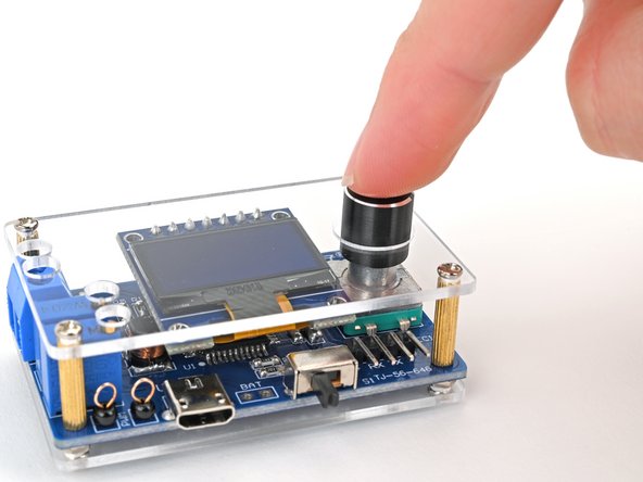
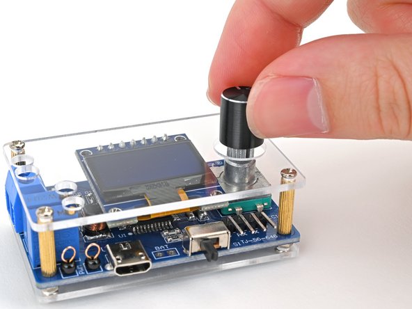
– Make sure to line up the hole in the bottom of the knob cover with the encoder knob like a pro.
– Gently pop the knob cover onto the encoder knob and give it a little push until it clicks into place.
Step 63


– Plug that Micro USB cable back into the oscilloscope and get ready to roll!
Step 64

Awesome job! You’ve just created your very own mini oscilloscope.
– Flip that switch to the ON position and let your oscilloscope spring to life!