How to Fix a Solder Bridge – Soldering Skills Guide
Duration: 45 minutes
Steps: 7 Steps
Solder bridges are a common hiccup in the soldering journey. This guide is here to help you tackle a solder bridge and test your circuit afterward. A solder bridge can create a serious mess by causing a short circuit, which means too much current flows through a component, potentially leading to device drama. We’re focusing on how to dodge a risky short by clearing a solder bridge that’s squatting between the power and ground rails on your circuit board. Just a heads up, this guide involves working with high temperatures when desoldering and soldering, so be sure to keep your cool and take the right precautions while the soldering iron is doing its thing. You might find yourself repeating some steps as you navigate the soldering and desoldering dance. If you’re just starting out, check out the How to Solder and Desolder Connections guide for some extra tips. And remember, if you need help, you can always schedule a repair.
Step 1

Heads up! The soldering iron tip is going to be super toasty! Handle it with care while you’re getting the job done.
Keep the soldering iron at a chill temperature—no need to crank it up to the max! Stick to your solder’s guidelines. Remember, too much heat can be a bummer for your components or board.
Different types of solder have unique melting points. Be sure to check the documentation that came with your solder to find out the ideal temperature for your project.
– Crank up that soldering iron to a toasty 300 °C (575 °F) and give it a moment to warm up to the perfect temperature. You’ve got this!
Tools Used

Step 2


A solder bridge is like a little connection party happening between two contact points (rails).
Want to check if everything’s connected properly? Grab a multimeter and see if there’s continuity (a short) in the mix!
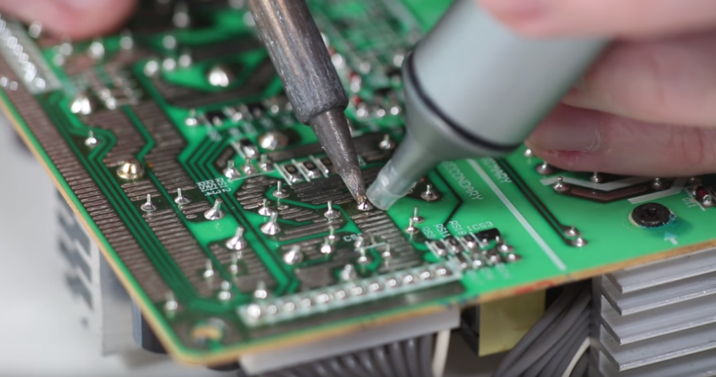
– First things first, let’s find that pesky solder bridge on the circuit board. It’s hiding somewhere waiting for you!
– Now, grab your solder wick and gently place it on the trouble spot. It’s time to wick away those worries!
Tools Used

Step 3


Careful now! The solder wick is going to be sizzling hot! Steer clear of the area near the soldering iron to keep your fingers safe and sound.
If you’re feeling crafty, grab those wire cutters and snip off about 2 cm (0.75″) of braid. Tweezers or needle nose pliers will be your trusty sidekicks to position it just right, as mentioned earlier.
Want to make desoldering a breeze? A little soldering flux can do wonders by cutting through those pesky oxide films. You’re almost there!
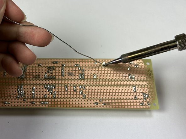
– Place the solder wick over the solder bridge, then grab your trusty soldering iron and give it a little heat by pressing it down on the area that needs some love.
– Keep that pressure on with the soldering iron until you see the solder melt and get happily absorbed by the wick.
Tools Used

Step 4

Careful now! The area you’re fixing is going to be quite toasty! Steer clear of touching that hot spot.
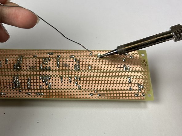
– Bring that soldering iron to the contact point and give it a warm hug.
– Once the contact point is feeling toasty, show it some love by reapplying the solder.
– Keep feeding the solder to the contact point until that pin is securely in place and the rails are happily apart.
Tools Used
Step 5


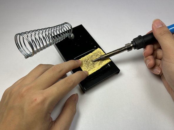
Watch out! The tip of the soldering iron is super hot! Handle it with care while you work your magic.
– Give that damp sponge a good hold, it’s your trusty sidekick!
– Once the soldering iron is feeling hot, glide it across the sponge with a gentle rubbing motion to whisk away any pesky excess solder clinging to the tip.
– After you’ve tidied up the iron, melt a tiny bit of solder on it to give the tip a fresh ‘re-tin’ makeover.
Tools Used
Step 6

– First up, grab that red (positive) probe and plug it into the Voltage and Resistance Socket. You’re on the right track!
– Next, take the black (negative) probe and connect it to the Common/Ground Socket. Teamwork makes the dream work!
– Now, twist that multimeter knob to the continuity testing setting. Look for those cool diode or audio symbols—you’re almost there!
Tools Used
Step 7

Before diving into the next steps, make sure the circuit board is as calm as a Sunday morning—no current should be flowing through it! If you find any sneaky current hanging around, it could lead to some serious multimeter meltdowns!
– First, grab that black probe and connect it to the circuit board rail where one side of the solder bridge used to hang out.
– Next up, take the red probe and connect it to the other side of the circuit board rail where the solder bridge was chillin’.
– Now, here’s the moment of truth! If everything’s gone smoothly, your multimeter should proudly display ‘OL’ on the screen, which means you’ve got an open circuit! No beeping? Great news! That means those rails are no longer connected and you’re on the right track.