DIY iPad Wi-Fi Front Panel Assembly Replacement Guide
Duration: 45 minutes
Steps: 24 Steps
Ready to give your iPad Wi-Fi a little makeover? This guide will walk you through the fun process of swapping out that front panel. Let’s dive in and get your device looking sharp again!
Step 1


Put on those safety glasses to keep your eyes safe, and watch out for that delicate LCD screen—it’s more fragile than it looks!
– If your display glass has taken a hit, let’s keep it from shattering further and protect yourself while you tackle this repair by putting some tape on it.
– Grab some clear packing tape and lay overlapping strips over the iPad’s display until you’ve got the whole face covered like a protective shield.
– Try your best to follow the rest of the guide as we go along. Just a heads up, once the glass is cracked, it might keep on cracking as you work, so you may find yourself using a metal prying tool to scoop out the pieces.
Step 2


– There are 14 metal clips keeping the display assembly snug and secure, as seen on the left. When you start prying in the next steps, try your best to work around these clips instead of slicing through them with your opening tool. You’ve got this!
Step 3


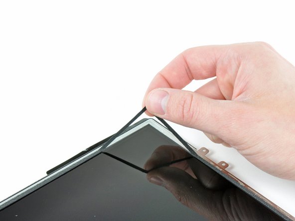
– Slide a metal spudger into the gap between the top edge of the display assembly and the rear panel assembly.
– Gently twist the spudger away from you to pop those tabs loose along the top edge of the display.
– Grab a second metal spudger and tuck it between the top edge of the display assembly and the rear panel assembly to keep those pesky tabs from snapping back into place.
Tools Used

Step 4


Gently pry away—if you hit a snag, take a breather and try a different spot.
– Grab your trusty spudger and glide along the right edge of the iPad like a pro!
– The front panel is snugly held to the aluminum back with metal clips at the top, bottom, and left sides. Meanwhile, the right side is chillin’ with plastic tabs that fit into little recesses on the backplate.
– Once you’ve freed those clips, gently lift the left side of the front panel and slide it to the left to pop those tabs out from the aluminum backplate.

Step 6

– Alright, let’s get those cables disconnected! In the next few steps, we’ll tackle the task of detaching the three cables that connect the display assembly to the logic board. These cables are linked to some important components, so let’s handle them with care!
Step 7


Just a friendly reminder: make sure you’re flipping up the retaining flap and not the socket itself. You’ve got this!
– Grab your trusty plastic opening tool and gently lift up those little retaining flaps that are keeping the digitizer ribbon cables snug in their spots on the logic board.
– Now, with a steady hand, pull those digitizer ribbon cables straight out of their cozy homes.
Step 8

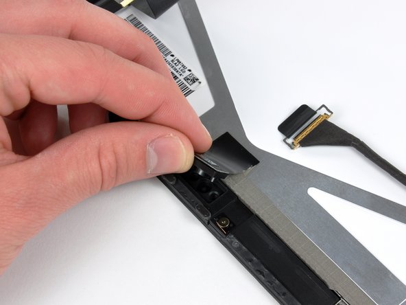
– Grab a plastic opening tool and gently nudge the ambient light sensor connector upwards to pop it out of its socket. You’ve got this!
Step 9


Gently slide the connector straight out, keeping it parallel to the logic board’s surface. You’ve got this!
– Gently flip up the metal retainer using its handy black plastic pull tab to disconnect the display data cable from the main board.
– Now, just give that cable connector a little tug and pull it away from its socket. You’ve got this!
Step 10

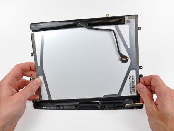
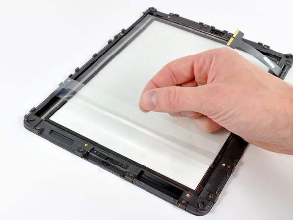
– Carefully detach the display assembly from the rear panel assembly.
Step 11


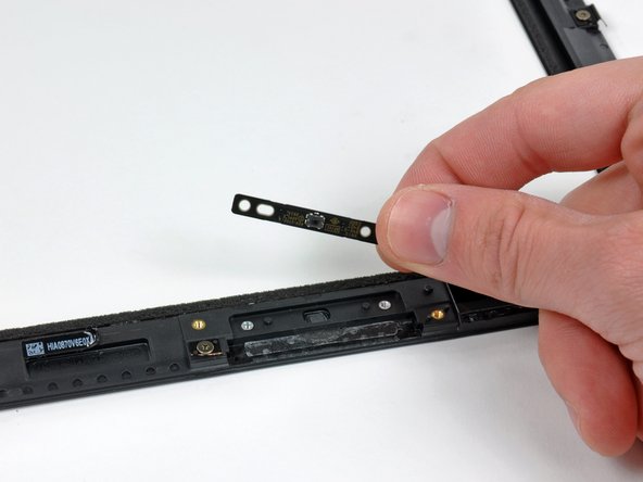
Handle the ambient light sensor with care! Avoid creasing the section below its top, as the adhesive part could decide to break away. Keep it cool and steady!
If you’re planning to give that LCD a second chance, there’s no need to worry about peeling off the ambient light sensor from the back. Just leave it be and keep the good times rolling!
– Grab your trusty plastic opening tool and gently nudge the ambient light sensor board away from the adhesive that’s holding it to the display frame. Take your time—it’s a delicate dance!
– Once you’ve got enough wiggle room, peel the ambient light sensor away from the LCD. Easy peasy!
– If you need to, go ahead and attach the plastic view window to your shiny new ambient light sensor before you pop it into place. You’ve got this!

Step 13


– First off, let’s tackle those three T5 Torx screws holding down the clips and LCD brackets wrapped in EMI tape near the home button switch. Unscrew them with care!
– Next, gently peel away the display clip along with its trusty tape from the black plastic display frame. Take your time; we want to keep everything in one piece!
– If you’re swapping out the LCD, don’t forget to transfer those little pieces of EMI tape and their clips to the new LCD. They’re important little buddies!

Step 15


Just a friendly reminder: don’t go overboard bending that LCD! It’s made of glass, and we all know how fragile that can be. Keep it gentle, folks!
– Slide the edge of your trusty plastic opening tool under one of the little ears on the steel LCD frame. It’s like giving it a gentle nudge!
– Give that plastic tool a twist to carefully lift the LCD away from the adhesive that’s holding it snugly against the front glass panel. You’re doing great!


Step 18

– If your device is still clinging to the front panel, gently peel off the strip of EMI tape located near the ambient light sensor socket.
– If needed, move this tape over to your shiny new LCD.
– If the tape is stuck to the LCD you’re keeping, just skip this step. But if you’re swapping out the LCD too, make sure to transfer that EMI tape to your new one.
Step 19

– If they’re still looking good, go ahead and move the clips and EMI tape from the bottom of the old LCD to your shiny new one!
Step 20

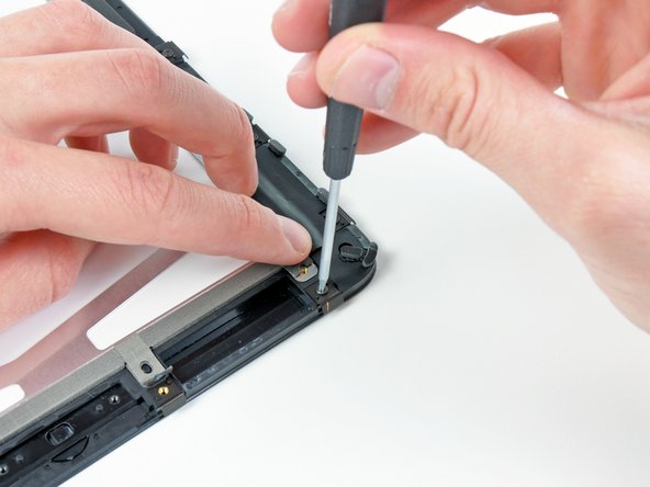
– Let’s get started! First, carefully take out the two T5 Torx screws that are holding the home button switch snugly against the plastic display frame.
– Next up, gently lift the home button switch board away from the front panel assembly. You’ve got this!
Step 21

– If you’re giving your LCD a second chance, grab a plastic opening tool and gently lift a corner of that foam tape hugging your LCD.
– Peel away the tape from around the edges of the glass face of your LCD. It’s like unwrapping a gift, but way more satisfying!
Step 22

Watch out for those pesky fingerprints and dust on the inner side of the front panel! They can really stand out when your device lights up. Keep it clean and shiny for a better view!
– Carefully peel away the yellow tape that’s holding the digitizer cable snugly against the inner side of the front panel assembly. Just a little caution here—let’s avoid tearing that cable while we’re at it!
– Gently remove the protective sheeting from the inner face of the front panel assembly. It’s like unwrapping a present, but way cooler!
Step 23

Make sure the LCD screen is squeaky clean before you dive in!
Step 24

When swapping out your panel for a shiny new one, keep an eye out for any protective film that might be clinging to the outside or inside of the frame. Don’t forget to peel that off before you proceed!
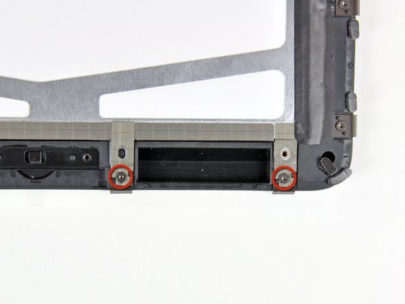
– Gently pull back the EMI tape along the bottom edge of the LCD while you unscrew the two T5 Torx screws that hold those pesky retaining clips in place.
– Now, give that tape a little love and stick it down onto the new clips before reinstalling those two T5 Torx screws.