DIY Guide to Soldering Techniques for Electronics Skills Kit Tools
Duration: 45 minutes
Steps: 39 Steps
Heads up! Tinkering with your device can be a bit tricky. If you find yourself in a jam or need a helping hand, don’t hesitate to schedule a repair. We’ve got your back!
Congrats on snagging our Level 1 Soldering Kit! You’re all set to dive into the world of through-hole soldering. This guide will walk you through each step, while also teaching you about soldering techniques, how to read resistors, and understanding component polarity. Before you know it, you’ll be ready to tackle that battery replacement in your iPod Nano 3rd Generation. If you need help, you can always schedule a repair.
Step 1


Through-hole soldering is often seen as the easiest type of soldering. It’s a great starting point for anyone looking to dive into the world of electronics repair!
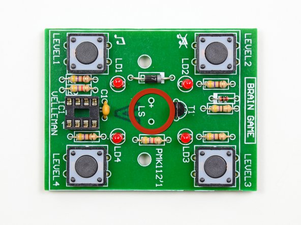
– Before we jump into assembling your brain game, let’s chat about the art of through-hole soldering.
– So, what’s the deal with through-hole, you wonder? Well, take a peek at that circuit board, and you’ll spot a bunch of holes, each sporting a copper trace on the back. The leads of your components slide right through these holes (hence the name through-hole) and get cozy with the copper trace when we solder them in.
Step 2


It’s always smart to rock a pair of safety goggles while you’re soldering. Those hot bits of solder can sometimes take a little leap, and trust us, a searing piece of metal in your eye is not the kind of surprise anyone wants to deal with. Stay safe and keep those peepers protected!
– Your trusty soldering iron is the star of the show! For this task, we’re going to be using the awesome soldering station available in our parts and tools store.
– When it comes to soldering, keep that iron under 40 watts at the tip. Our station pulls 50 watts from the wall, so feel free to turn it up to the max without worry.
– If you’re firing up your soldering iron for the first time, you might see a bit of smoke and catch a whiff of something not-so-great. No need to panic; that’s just the tip’s coating burning off. Give it a couple of minutes to settle down.
– Before diving into soldering, make sure to give your cleaning sponge a little moisture. A dry sponge? That’s just asking for trouble!
Tools Used

Step 3

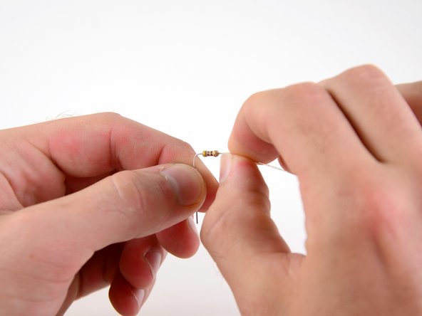
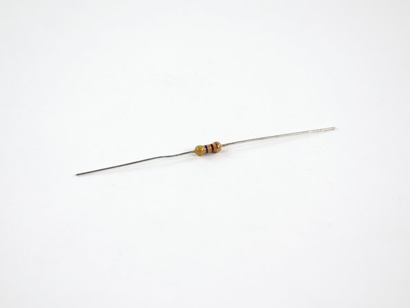
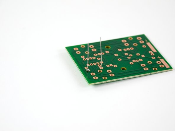
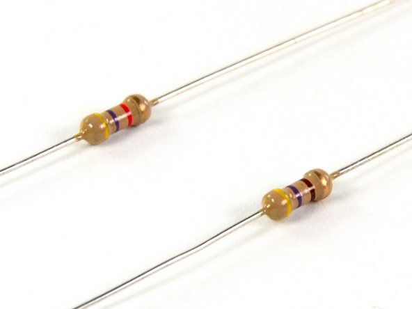
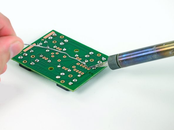
– Let’s kick things off with resistor R1 from your kit! Look for the one adorned with yellow, purple, brown, and gold rings (we’ll dive into what those colors mean a little later).
– Now, give those leads a little bend – we want them at a sharp 90-degree angle, about 1.5 mm from the body of the resistor. You’ve got this!
Step 4
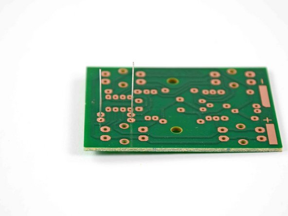

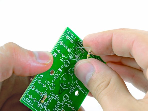
– Pop those resistor leads right through the holes on either side of the rectangle labeled R1 on the circuit board. You’ve got this!
– Now, give the board a little flip so the copper traces are facing up and those resistor leads are standing tall like they just won a medal, just like in the second picture.
Step 5


Keeping your soldering iron clean and giving it a little tinning while you work will help you create awesome solder joints and extend the life of your tip. Remember, a happy tool makes for happy repairs!
– Alright, it’s time to get your soldering iron ready for some action! But first, let’s prep that tip like a pro.
– Once your soldering iron is heated up, give it a little TLC by melting a tiny bit of solder on the tip and then wiping it off with your damp sponge. It’s like a spa day for your iron!
– Now, let’s add another small dollop of solder to the tip and leave it there. This is known as ‘tinning’ the iron, and it’s a game changer for heat conductivity, helping you solder faster and smoother!
Tools Used
Step 6

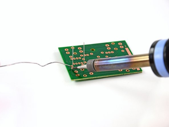
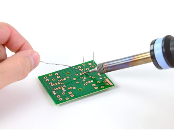
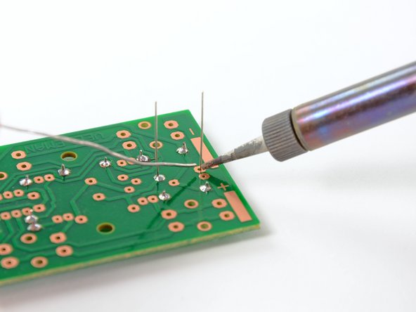
– Here we are, folks! It’s the moment we’ve all been waiting for—let’s get that solder flowing!
– Place the tip of your soldering iron on the two parts that need to be buddies: the resistor lead and the copper trace on the circuit board.
– Now, give your solder a little love by touching it to the iron’s tip to melt it onto the joint. Just don’t overstay your welcome—keep it there for just a second or two.
– With a bit of flair, swiftly pull both the soldering iron and the solder away from the joint—no need to rush, but keep it smooth!
– Your solder joint should look like a shiny, conical masterpiece, staying neatly within the bounds of the copper trace.
Tools Used
Step 7
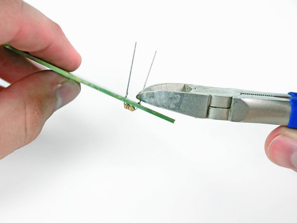

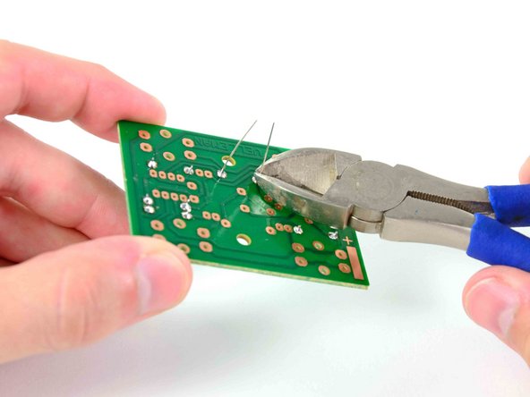
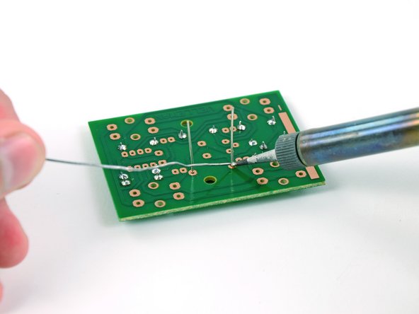
– Just like before, go ahead and solder that second resistor lead to the circuit board. You’ve got this!
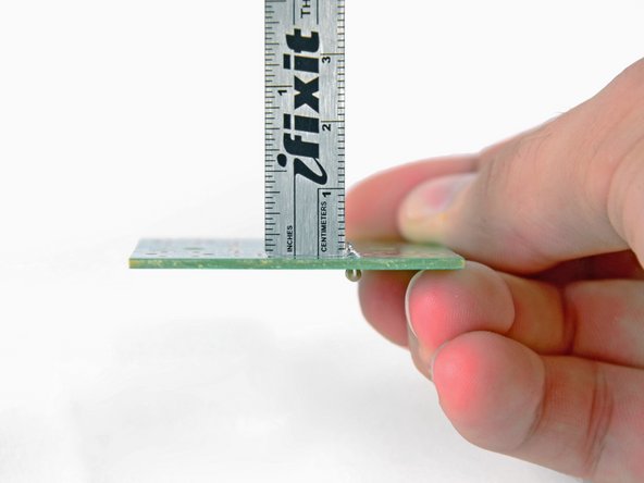
– Time to tidy up! Use a pair of wire cutters to trim off any extra lengths of the resistor leads. Remember, NASA says anything up to 2.29 mm is totally cool!
Step 8


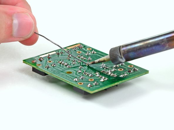
– Hey, we all slip up sometimes, especially when diving into new skills. Soldering is no different, so if your solder joint didn’t quite turn out right, here’s how to fix it.
– Start by placing a piece of desoldering braid over the solder that needs attention. Then, press the tip of your soldering iron down onto the braid. This will warm up both the solder and the braid.
– Watch as the solder flows from the joint into the desoldering braid. Once that’s done, carefully lift both the braid and the soldering iron off the board. You should have a nice clean contact to work with now. Don’t forget to use wire cutters to snip off the used end of the desoldering braid.
Tools Used

Step 9
Are you ready to check out the resistance of that bottom resistor? Let’s get to it!
– Alright, let’s dive into the world of resistors! These little components are essential in circuits, helping us manage how much current flows. Remember, the higher the resistance (measured in Ohms, Ω), the less current sneaks through.
– Now, what’s the secret to figuring out the resistance? It’s all in the colorful bands on the resistor! Grab a resistor color code chart, and you’re golden.
– If your resistor has four bands, start by spotting the red, gold, or silver band on one of the chubby ends—those are the tolerance bands. With our resistors sporting gold bands, we can confidently say the actual resistance is within ±5% of the nominal value.
– Next up, let’s uncover the nominal value of your resistor. Start from the opposite end of the tolerance band and move left to right; you’ll find three colored bands. The first two bands will give you a number (0-9), and the third band is a multiplier that tells you the power of 10.
– Looking at the top resistor, we’ve got yellow, violet, and red bands. Check your resistor color code chart, and you’ll see those correspond to 4, 7, and 100, leading us to a nominal resistance of 4,700 Ω. Easy peasy!
Step 10

– Pop in the last three 470 Ω resistors (yellow/violet/brown) into the slots labeled R2, R3, and R4. You’ve got this!
Step 11

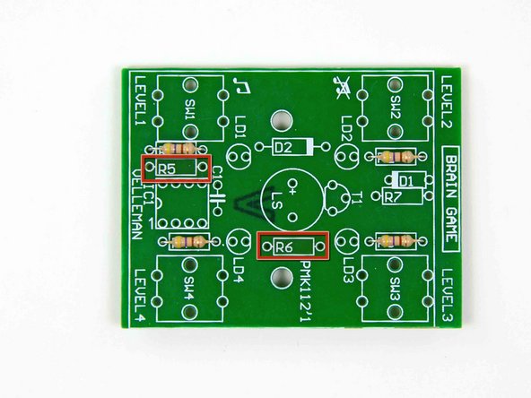
– Time to dig into your kit and grab those two yellow, violet, and red resistors! They’re the stars of this show.
– Now, let’s get those resistors installed into the R5 and R6 terminals on the circuit board. You’re doing great!
Step 12


– First things first, find that single yellow/violet/black resistor hanging out. It’s ready to shine!
– Once you’ve got it, pop that resistor into the terminal labeled R7 on the circuit board like a pro!
Step 13

– Take a moment to rummage through your kit, and you might just stumble upon some intriguing components with long leads waving hello.
– Say hello to diodes—think of them as the traffic cops of circuitry! Their main gig is to ensure that current flows in one direction only, from anode to cathode, while blocking any reverse traffic. Current comes in through the anode (the positive side) and exits via the cathode (the negative side).
– Since these little guys only let current cruise in one direction, it’s super important to install them the right way around. Look for the stripe on the diode; that’s your hint for which side is the cathode.
Step 14


Ensure that the cathode, which has a little black band, aligns perfectly with the white stripe located to the left of the D1 label on the circuit board.
– Gently bend the legs of the tiny red diode and pop them into the terminal labeled D1.
– Now, use the same technique you used to solder those resistors onto the board to attach the diode. You’ve got this!
Step 15

Make sure to match up the gray end of the diode with the side of the terminal that has the cathode label. It’s a simple step, but it makes all the difference!
– Pop in the bigger, black diode into the spot labeled D2 and you’re on your way!
Step 16


– Every game needs some buttons to play, so let’s get those on the board next!
– Gently insert the leads of the four buttons into the designated spots labeled SW1 through SW4.
– Don’t worry about the orientation of the buttons; just make sure the leads are snugly seated in their holes.
Step 17


– Get those soldering skills ready because it’s time to attach each lead for every button! You’re going to do great.
– Soldering the buttons is just like working with resistors and diodes, but with one little twist: no need to trim any extra leads after you’re done. Easy peasy!
Step 18
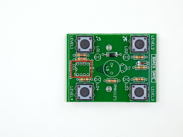

– Now it’s time to install the IC socket, also known as the CPU socket! Think of it as a cozy little home for your processor, allowing it to connect to the printed circuit board without any messy soldering. This way, swapping out your processor becomes a breeze, avoiding the stress of potential damage.
– Carefully guide those eight leads of the IC socket through the holes in the rectangle labeled IC1. Just be sure that the semi-circle at the top of the socket is aligned perfectly with the semi-circle printed on the edge of the rectangle. It’s like a little puzzle piece fitting into place!
– Flip the board over and get ready to solder those leads down. Just like when you solder the buttons, there’s no need to trim any excess leads. You’ve got this!
Step 19


Ensure that the printed markings on the capacitor are facing away from the IC socket so you can easily read them. Keep it clear and simple, just like we like our repairs!
– Let’s get ready to install the bright yellow capacitor! These little guys are like energy superheroes, storing electrical charge to give circuits a quick boost when they need to shine a light or make a sound.
– Capacitors are measured in Farads, which is just a fancy way of saying it’s the ratio of electrical charge on each conductor compared to the potential difference between them. This particular superstar is a 1 µF capacitor.
– Pop that capacitor into the terminal right next to the IC socket marked C1. Soldering the leads is a breeze—just follow the same through-hole procedure we’ve been using so far!
Step 20


– Time to light things up! We’re diving into the world of LEDs. These little light-emitting diodes are the rock stars of electronics, shining bright in all sorts of colorful ways.
– You’ll be placing four fabulous LEDs into the terminals labeled LD1 through LD4. Make sure they’re all in their right spots!
– When you pop those LEDs in, remember: the shorter lead goes into the hole next to the flat side of the printed circle. Simple as pie!
Step 21


– Attach each LED to the circuit board, and trim any extra lead length to keep things neat and tidy!
Step 22

– Hey there, check out this neat electrical component! Isn’t that cool?
– Transistors are the little heroes that boost and switch electrical signals. They can either pump up an input voltage or act as electronic on-off switches. Pretty nifty, right?
– When you’re installing a transistor, just remember: each lead has its own special job! Make sure to solder them to the right spots for everything to work smoothly.
Step 23


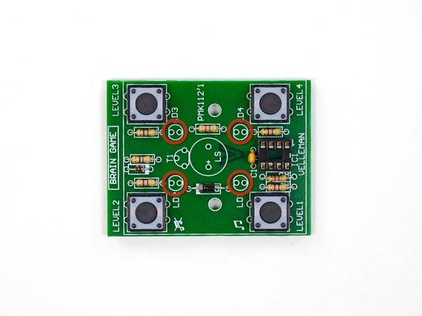
– First, find the semi-circle marked T1 and carefully slide those three leads through the holes like a pro.
– Next up, give those leads a warm welcome by soldering them to the board, then trim off any extra bits. You’re doing great!
Step 24
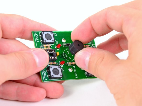

– Let’s make sure your solder project has a killer sound system… or this speaker will do just fine, right?
– Carefully thread the leads through the holes in the circle marked LS, ensuring that the positive terminals are aligned perfectly.
Step 25


The leads might not be super long, but don’t forget to give them a little trim after you’re done soldering!
– Connect the two speaker wires to the circuit board with a little solder magic.
Step 26


If the solder isn’t behaving as expected, no worries! Just grab your iron and give it another go, or sprinkle on some extra solder for good measure.
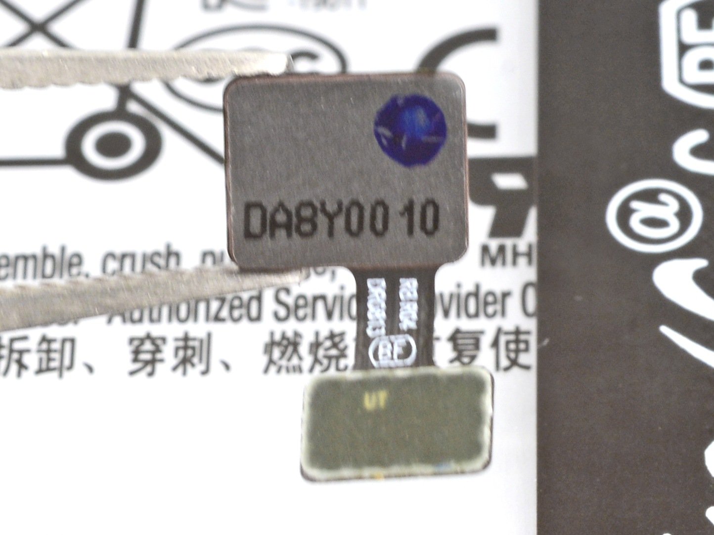
– Surprise! You thought you were just diving into the world of through-hole soldering, but guess what? This kit also comes with a free intro to surface-mount soldering! It’s a nifty technique often used for attaching batteries to circuit boards in devices like iPods.
– Now, let’s get that soldering iron ready! Place the tip of your iron on the big copper negative solder pad. This will help the heat flow through the pad, making your soldering journey a breeze.
– Next up, touch your solder to the tip of the iron and keep feeding it until you’ve created a smooth, dome-shaped solder blob on the copper pad. You’re doing great!
Tools Used
Step 27


– Now, let’s do the same magic for that positive solder pad, shall we?
– By the end of this, you should have two smooth, shiny, and perfectly formed solder domes, just like little solder cupcakes!
Step 28

If things don’t go as planned the first time, no worries! Just reheat that solder or add a little extra to get it just right.
– Nope, you didn’t get scammed; those two leads are meant to be empty in the middle.
– To attach the battery leads to the circuit board, place the tip of your soldering iron on the solder already on the positive pad.
– As the solder starts to melt, quickly slide the end of the lead into the gooey solder so it dangles off the side of the board, just like in the picture.
– Remove the soldering iron and give the solder a moment to cool and grip that lead snugly.
Tools Used
Step 29

– Repeat the surface mount soldering process for the negative battery terminal lead. Make sure to position the lead so that any extra wire dangles off the opposite side instead of the positive terminal lead.
– Now that you’ve added some whiskers to your circuit board, it’s time to give it some love and maybe even get it a scratching post. Just kidding! Let’s keep our focus on the repair.
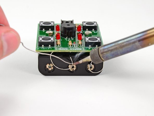
Step 30

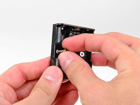
– Pop those two Phillips screws right into the holes located on the underside of the battery compartment. You’ve got this!
Step 31

– Use two fingers from one hand to cover the screw heads, giving them a little hug.
– While keeping those fingers in place, take hold of the battery compartment with your thumb and give it a gentle flip. You’ll see the screw threads peeking out from the top side of the battery compartment, ready for action!
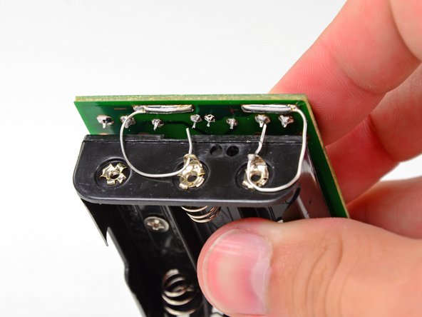
Step 32

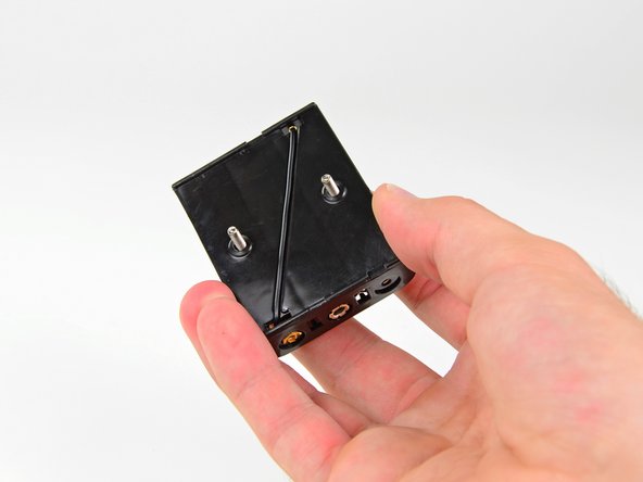
– With one hand, gently position the two metal spacers onto the screw threads, placing one on each screw. You’re doing great!
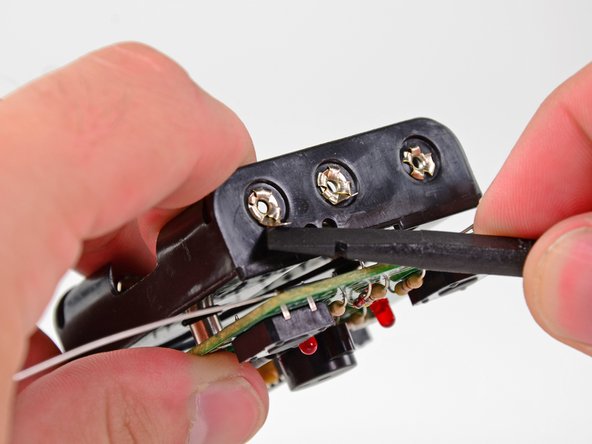
Step 33

Step 34

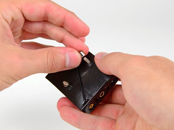
– Grab your trusty 5.5 mm nut driver or socket and place it right over one of those battery compartment screw nuts. You’ve got this!
– Now, let’s flip that circuit board over like a pro!
– With one hand holding the socket steady, use your Phillips #2 screwdriver to tighten that battery compartment screw. Feel the power!
– Rinse and repeat for the other battery compartment screw. You’re almost there!
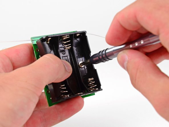
Tools Used


Step 36


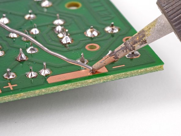
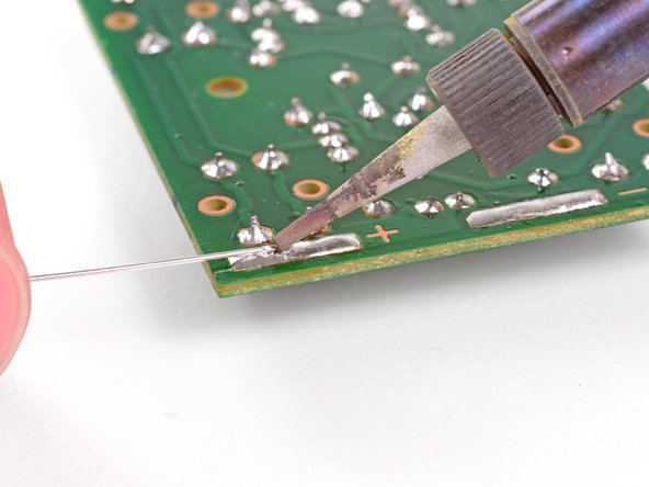
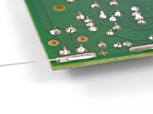
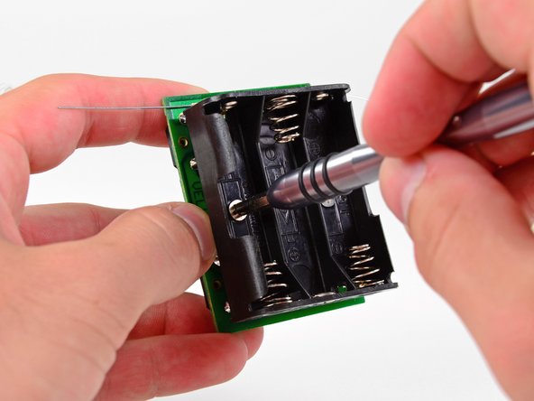
– Grab a trusty pair of wire cutters and snip away about an inch of the positive terminal surface mount lead.
– Now, give that lead a little twist and thread it through the positive ring terminal on the battery compartment.
– Show off those awesome through-hole soldering skills and secure that lead to the battery terminal with a nice solder.
– Don’t forget to trim off any extra lead that might be sticking around.

Step 38


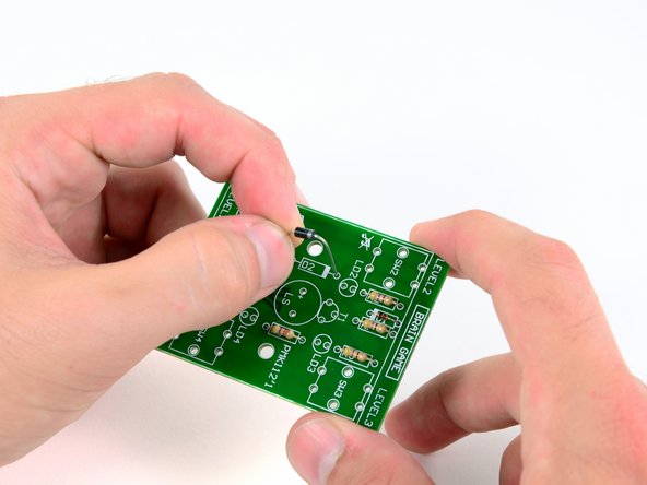
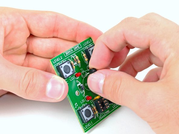
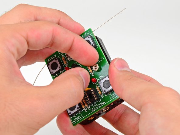
– Time to wrap up our circuit board adventure with the installation of the central processing unit, or CPU—the superstar of the Brain Game!
– Look closely at one end of the CPU; it has a tiny notch. When you’re placing the CPU, ensure that this notch matches up with the cutout on the IC socket. It’s like a puzzle piece!
– Gently press the eight pins into their cozy spots in the IC socket. You’ve got this!
– And just like that, you’ve mastered the Level 1 Through-Hole Soldering Kit! High five!
Step 39


– Pop in three AA batteries into the battery compartment and get ready to power up!
– Once you’ve placed the last battery in, watch as those four LEDs start to twinkle in a fun clockwise dance. Awesome job, you did it!
– Ready to dive into the game? Just follow these steps:
– Enjoy yourself! And don’t forget to share your epic high scores with us in our Story section.