How to Replace iPad 3G Headphone Jack Microphone Assembly
Duration: 45 minutes
Steps: 15 Steps
Hey there, repair rockstar! Just a friendly heads-up: take your time with this process and make sure you’re following the steps closely. If you find yourself in a jam, no worries! You can always schedule a repair and let the pros handle it. You’ve got this!
Get ready to swap out that microphone/headphone jack like a pro! Follow this guide to tackle the assembly with confidence and ease. If you need help, you can always schedule a repair.
Step 1


Put on those safety glasses to keep your peepers safe, and remember to treat that LCD screen with the care it deserves!
– If your display glass is shattered, let’s keep those pesky shards in check and avoid any accidental injuries while you tackle this repair by using some tape.
– Grab some clear packing tape and lay down overlapping strips over your iPad’s screen until it’s fully covered.
– Do your best to follow the rest of the guide as outlined. Just a heads up, once the glass starts to break, it might keep cracking as you work, so you may want to use a metal prying tool to carefully scoop out the broken pieces.
Step 2


The iPad in the pictures might have a slightly different look than yours, but don’t worry—the steps are exactly the same!
– Slide a metal spudger between the right edge of the display assembly and the rear panel assembly. You’re doing great!
– Gently twist the spudger away from you to pop those pesky tabs loose along the top edge of the display. Almost there!
Tools Used

Step 3


– Slide a second metal spudger between the top edge of the display assembly and the rear panel assembly to prevent those pesky tabs from snapping back into place.
– Gently pry the display assembly away from the rear panel. You’ve got this!
Tools Used
Step 4


Approach the top edge of the iPad with care! The digitizer ribbon cable is hanging out near the rear panel edge, and it’s a bit sensitive. Treat it gently to avoid any mishaps!
– Keep gently working the display assembly away from the rear panel, focusing on the bottom and left edges of your iPad. You’re doing great!
Step 5

Be gentle when lifting the display assembly off the iPad! There’s a delicate antenna cable with just a smidge of slack connecting the two parts, and we wouldn’t want to stress it too much. Keep it cool and take your time!
– Gently pry the display assembly away from the rear panel assembly, starting from the bottom edge. You got this!
Step 6

– Gently slide the flat end of your spudger under the antenna connector that’s nearest to the bottom of the iPad and carefully lift it off its socket on the communications board. You’ve got this!
Step 7

– Alright, let’s get this party started! First up, we’re going to carefully unplug the three cables that link the display assembly to the logic board. These cables are responsible for some pretty important components, so handle them with care!
Step 8


Remember to gently lift the retaining flap, not the socket itself! You’ve got this!
– Grab your trusty iPod opening tool and gently lift those little retaining flaps that are keeping the digitizer ribbon cables snug in their homes on the logic board.
– Once the flaps are up, just pull the digitizer ribbon cables straight out of their cozy sockets. Easy peasy!
Step 9

– Grab your trusty iPod opening tool and gently pry the ambient light sensor connector upward from its socket. You’ve got this!
Step 10

Gently slide the connector out parallel to the face of the logic board. Keep it smooth and steady, just like a pro!
– Start by gently flipping up the metal retainer using the black plastic pull tab to release the display data cable from the main board. You’ve got this!
– Now, carefully pull the cable connector away from its socket. Easy peasy!
Step 11

– Carefully detach the display assembly from the rear panel assembly. Remember, patience is key!
Step 12

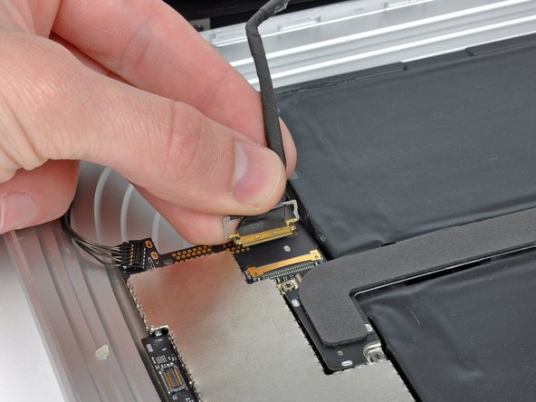
Remember to gently lift the cable retaining flap instead of tugging on the socket itself. You’ve got this!
– Grab your trusty iPod opening tool or just your fingernail and gently lift the ZIF cable retaining flap on the headphone jack socket. You’ve got this!

Step 14

– Let’s get started by unscrewing those two 2.8 mm T5 Torx screws that are holding the headphone jack snugly in the rear case. You’ve got this!
Step 15

Don’t forget to move the rubber sound channel from your old microphone to the new one. It’s a little detail that makes a big difference!
– Let’s kick things off by carefully taking out the headphone jack from the back of the case. No rush, take your time!
– Before you put those screws back in, double-check that the headphone jack is snugly fit into its little home at the top edge of the rear case. It should feel just right!