How to Replace Apple iPad 3G Front Panel Assembly Guide
Duration: 45 minutes
Steps: 29 Steps
Hey there, savvy fixer! Just a friendly reminder to take it easy while you’re working on your device. If things get a bit tricky or you’re feeling stuck, no worries at all! Just remember, you can always schedule a repair and let the pros handle it. Happy repairing!
Ready to give your device a makeover? This guide will help you swap out that shattered front glass panel for a brand-new look. Let’s dive in and bring your gadget back to life!
Step 1


Put on those safety glasses to keep your peepers protected, and watch out for that LCD screen—it’s more delicate than it looks!
– If your display glass is cracked, let’s keep things safe and sound! Grab some tape and cover that glass to prevent any further shattering or accidental cuts during your repair adventure.
– Next up, lay down some overlapping strips of clear packing tape over your iPad’s display until the entire face is snugly covered. It’s like a cozy blanket for your screen!
– Now, follow the rest of the guide as best as you can. Just a heads-up: once the glass starts to break, it may keep cracking while you work. Don’t worry if you need to use a metal prying tool to help scoop out the pieces; you’ve got this!
Step 2


The iPad in the pictures might have a bit of a different look than yours, but don’t sweat it—the steps are the same!
– Slide a metal spudger into the gap between the right edge of the display assembly and the rear panel assembly.
– Gently rotate the spudger away from you to pop those tabs loose along the top edge of the display.
Tools Used


Step 3


– Slide a second metal spudger into the gap between the top edge of the display assembly and the rear panel assembly. This will help keep those pesky tabs from bouncing back into place.
– Gently pry the display assembly away from the rear panel. You’ve got this!
Tools Used
Step 4


Be super careful as you get close to the top edge of your iPad! The digitizer ribbon cable is hanging out near the rear panel edge and is a bit fragile. Treat it like a delicate flower and give it some love!
– Keep gently prying the display assembly away from the rear panel, focusing on the bottom and left edges of your iPad. You’ve got this!

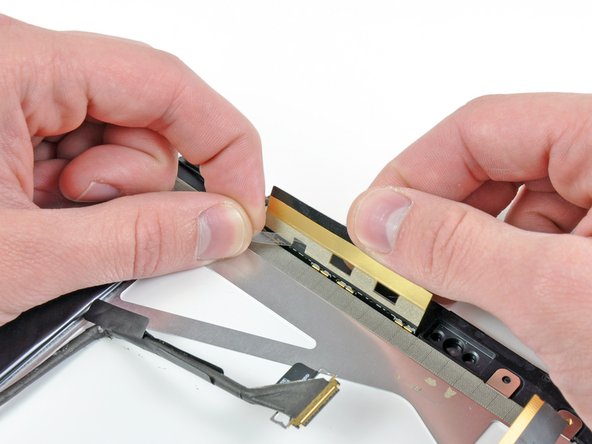
Step 6

– Grab your trusty spudger and gently wiggle the flat end underneath the antenna connector that’s closest to the bottom of your iPad. Give it a little pry to lift it off its cozy socket on the communications board. You’re doing great!
Tools Used
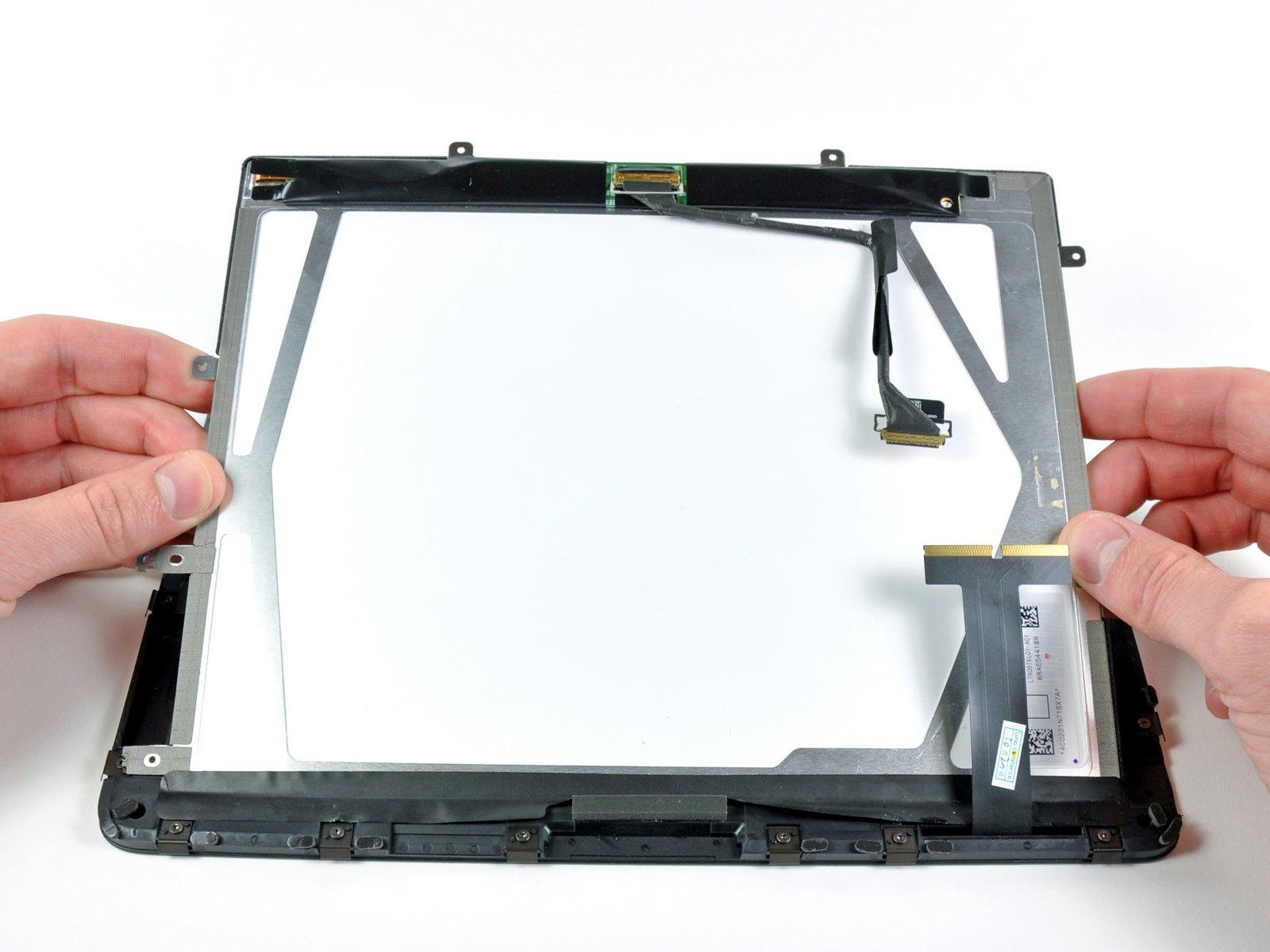
Step 7

– Get ready to detach those three cables connecting the display assembly to the logic board! These cables are responsible for some important components, so let’s take care as we unhook them. Ready? Let’s do this!
Step 8


Remember to lift the retaining flap, not the socket itself. You’ve got this!
– Grab your trusty iPod opening tool and gently lift up those little retaining flaps that are keeping the digitizer ribbon cables snug in their sockets on the logic board. You’ve got this!
– Now, with a steady hand, pull the digitizer ribbon cables straight out of their sockets. Easy peasy!
Step 9

– Grab your trusty iPod opening tool and gently nudge the ambient light sensor connector upwards to free it from its cozy socket. You’re doing great!
Step 10

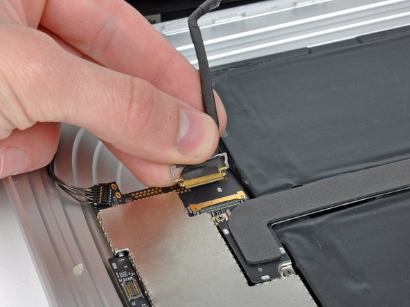
Gently pull the connector straight out, keeping it level with the face of the logic board.
– Gently flip up the metal retainer using the black plastic pull tab to free the display data cable from the main board.
– Now, just pull the cable connector away from its socket—easy peasy!
Step 11

– Gently detach the display assembly from the rear panel assembly. You’ve got this!
Step 12

If needed, gently peel away the foam tape covering the ambient light sensor.
– There’s no need to pull off all the foam tape from the antenna. Just give it a little love and leave it in place!
Step 13


If you need to, go ahead and pop that plastic view window onto your new ambient light sensor before you dive into the installation. You’ve got this!
– Grab your trusty iPod opening tool and gently work the edge under the ambient light sensor board. With a bit of finesse, you’ll pop it free from the adhesive that’s keeping it snug against the display frame.
– Once you’ve got a little wiggle room, just peel that ambient light sensor off the LCD with care. You’re doing great!


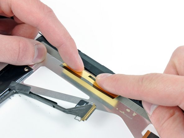
Step 16

– Grab that trusty iPod opening tool and gently slide it along the edge to peel the antenna away from the adhesive that’s keeping it snug against the top edge of the display. You’ve got this!
Step 17


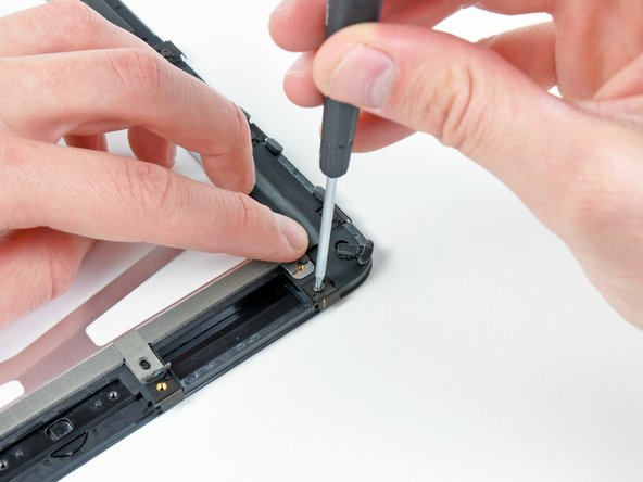
– First things first, let’s get those three T5 Torx screws outta the way! Unscrew the ones holding the clips and LCD brackets that are snugly covered in EMI tape near the home button switch.
– Now, with a gentle touch, peel back the display clip along with its trusty tape from the black plastic display frame. Easy does it!
– If you’re swapping out the LCD, don’t forget to pass those bits of EMI tape and their attached clips over to the new LCD. They need a new home too!

Step 19

– G
– e
– n
– t
– l
– y
–
– p
– e
– e
– l
–
– a
– w
– a
– y
–
– t
– h
– e
–
– t
– i
– n
– y
–
– s
– t
– r
– i
– p
–
– o
– f
–
– t
– a
– p
– e
–
– t
– h
– a
– t
– ‘
– s
–
– h
– o
– l
– d
– i
– n
– g
–
– t
– h
– e
–
– a
– n
– t
– e
– n
– n
– a
–
– l
– e
– a
– d
–
– s
– n
– u
– g
–
– a
– g
– a
– i
– n
– s
– t
–
– t
– h
– e
–
– L
– C
– D
– .
–
– Y
– o
– u
– ‘
– v
– e
–
– g
– o
– t
–
– t
– h
– i
– s
– !
Step 20


Handle the LCD with care—it’s glass, so no wild bending!
– Slide the edge of an iPod opening tool under one of the ears that are holding the steel LCD frame in place.
– Gently twist the iPod opening tool to lift the LCD away from the adhesive that’s keeping it stuck to the front glass panel.


Step 23

– C
– h
– e
– c
– k
–
– i
– f
–
– a
– n
– y
–
– s
– t
– u
– b
– b
– o
– r
– n
–
– E
– M
– I
–
– t
– a
– p
– e
–
– i
– s
–
– s
– t
– i
– l
– l
–
– c
– l
– i
– n
– g
– i
– n
– g
–
– t
– o
–
– t
– h
– e
–
– f
– r
– o
– n
– t
–
– p
– a
– n
– e
– l
–
– n
– e
– a
– r
–
– t
– h
– e
–
– a
– m
– b
– i
– e
– n
– t
–
– l
– i
– g
– h
– t
–
– s
– e
– n
– s
– o
– r
–
– s
– o
– c
– k
– e
– t
– .
–
– I
– f
–
– s
– o
– ,
–
– c
– a
– r
– e
– f
– u
– l
– l
– y
–
– r
– e
– m
– o
– v
– e
–
– i
– t
– .
–
– W
– h
– e
– n
–
– t
– r
– a
– n
– s
– f
– e
– r
– r
– i
– n
– g
–
– i
– t
– ,
–
– s
– l
– i
– d
– e
–
– i
– t
–
– o
– v
– e
– r
–
– t
– o
–
– y
– o
– u
– r
–
– b
– r
– a
– n
– d
–
– n
– e
– w
–
– L
– C
– D
–
– p
– a
– n
– e
– l
– .
–
– I
– f
–
– y
– o
– u
– ‘
– r
– e
–
– r
– e
– u
– s
– i
– n
– g
–
– t
– h
– e
–
– L
– C
– D
– ,
–
– f
– e
– e
– l
–
– f
– r
– e
– e
–
– t
– o
–
– s
– k
– i
– p
–
– t
– h
– i
– s
–
– s
– t
– e
– p
– .
–
– B
– u
– t
–
– i
– f
–
– y
– o
– u
– ‘
– r
– e
–
– s
– w
– i
– t
– c
– h
– i
– n
– g
–
– t
– h
– e
– m
–
– b
– o
– t
– h
–
– o
– u
– t
– ,
–
– m
– a
– k
– e
–
– s
– u
– r
– e
–
– t
– o
–
– t
– r
– a
– n
– s
– f
– e
– r
–
– t
– h
– a
– t
–
– t
– a
– p
– e
–
– o
– v
– e
– r
–
– t
– o
–
– y
– o
– u
– r
–
– s
– h
– i
– n
– y
–
– n
– e
– w
–
– L
– C
– D
–
– n
– i
– c
– e
– l
– y
– .
–
– N
– e
– e
– d
–
– a
–
– h
– a
– n
– d
– ?
–
– D
– o
– n
– ‘
– t
–
– s
– t
– r
– e
– s
– s
– ,
–
– y
– o
– u
–
– c
– a
– n
–
– a
– l
– w
– a
– y
– s
–
– <
– a
–
– h
– r
– e
– f
– =
– ‘
– h
– t
– t
– p
– s
– :
– /
– /
– w
– w
– w
– .
– s
– a
– l
– v
– a
– t
– i
– o
– n
– r
– e
– p
– a
– i
– r
– .
– c
– o
– m
– /
– r
– e
– p
– a
– i
– r
– ‘
– >
– s
– c
– h
– e
– d
– u
– l
– e
–
– a
–
– r
– e
– p
– a
– i
– r
– <
– /
– a
– >
– !
Step 24

– If they’re still looking good, go ahead and move those clips and EMI tape from the bottom of the LCD over to your new LCD. You’ve got this!
Step 25


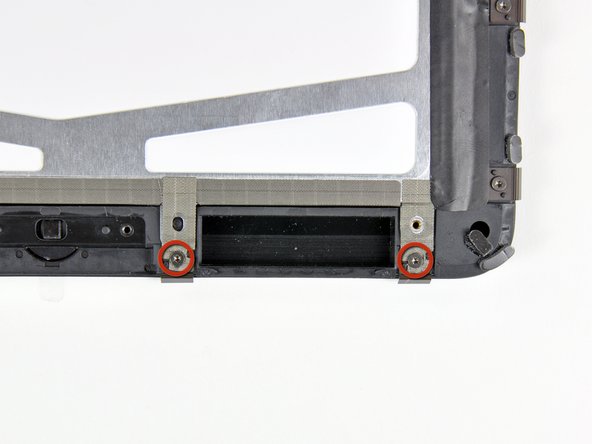
– First up, let’s tackle those two T5 Torx screws holding the home button switch snugly to the plastic display frame. Unscrew them with care!
– Once those screws are out of the way, gently lift the home button switch board from the front panel assembly. You’ve got this!
Step 26


– Ready to give your LCD some TLC? Grab a plastic opening tool and gently pry up a corner of that foam tape hugging your LCD. It’s like giving it a little hug back!
– Now, let’s tidy up! Carefully peel off the tape that surrounds the glass face of your LCD. It’s all about keeping things neat and tidy!
Step 27

Make sure the LCD screen is spotless before diving in!
Step 28

– Gently peel back those strips of EMI tape along the bottom edge of the LCD while you take out the two T5 Torx screws that are keeping those retaining clips snug and secure.
– Once you’ve got those clips in place, just stick the tape back down and reinstall those two T5 Torx screws. Easy peasy!
Step 29

– Peel off those two pesky pieces of protective film from the inner side of the GPS antenna. You’re almost there!
– Now, gently press the GPS antenna down onto the LCD. You’re doing great!


