DIY Guide to Replace MacBook Pro 13 Late 2011 Heat Sink
Duration: 45 minutes
Steps: 21 Steps
Hey there! Before you dive into the repair adventure, make sure to have all the right tools and a cozy workspace. Remember, if you ever feel stuck or need a helping hand, you can always schedule a repair. You’ve got this!
Is your MacBook Pro feeling a bit sluggish and hot, thanks to all that OEM thermal paste? Fear not! This guide will walk you through the steps to remove your heat sink and slather on some fresh thermal paste, helping your laptop cool down and perform like a champ. If you need help, you can always schedule a repair.
Step 1

– Let’s get down to business! First up, you’ll want to unscrew ten of those little guys. Grab your screwdriver and show those screws who’s boss!
Step 2


– Gently use your fingers to wiggle the lower case away from the MacBook’s body near the vent—it’s like giving it a little nudge!
– Carefully take off the lower case and reveal the treasures inside.
Step 3


Gently pry upward on both short sides of the connector to help it ease out of its socket. Just a heads up, the corners of the connectors can be a bit fragile, so handle them with care!
– Gently wedge the spudger under the battery connector and give it a little nudge upwards to free it from its cozy spot on the logic board. You’ve got this!
Tools Used

Step 4

– Gently nudge the battery cable a little away from its socket on the logic board to ensure it doesn’t accidentally reconnect while you’re in the zone.
Step 5


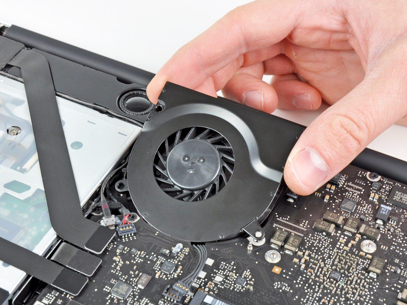
Check out the second and third pictures to spot the fan socket and the fan connector! Just a friendly reminder: as you gently use your spudger to lift the fan connector straight up and out of its socket, be careful not to break that plastic fan socket off the logic board. The layout of the logic board in the second picture might look a bit different from your device, but don’t worry—the fan socket is still the same!
Step 6

– Unscrew those three little screws holding the fan snugly to the logic board!
Step 7

– Gently lift the fan out of its cozy spot on the logic board, but keep an eye on that cable – it might try to tag along for the ride!
Step 8


– Gently coax the right speaker/subwoofer cable out from its cozy spot under the upper case’s retaining finger using the tip of a spudger.
– Now, lift the right speaker/subwoofer cable upwards to pop that connector out of its snug socket on the logic board.
Tools Used
Step 9

– Unplug the camera cable from the logic board and let’s keep things moving!
Step 10


To unplug those cables, grab the flat end of a spudger and gently lift their connectors away from the logic board sockets. You’ve got this!
– Unplug these four cables, and you’re on your way to a smooth repair!
Tools Used
Step 11


Make sure you’re lifting up on the hinged retaining flap, not the socket itself. You’ve got this!
– Gently lift the retaining flap on the keyboard ribbon cable ZIF socket using your fingernail. You’ve got this!
– With the spudger’s tip, carefully pull the keyboard ribbon cable out of its cozy socket.
– If the cable is being a little stubborn, no worries! You can stick a piece of tape to the cable to help guide it into the socket smoothly.
Tools Used

Step 13


Make sure you’re gently lifting the hinged retaining flap, and not the socket itself. You’ve got this!
– Grab your trusty spudger or just your fingers, and gently lift the retaining flap on that keyboard backlight ribbon cable ZIF socket. You’ve got this!
– Now, give that keyboard backlight ribbon cable a little tug and slide it right out of its socket. Easy peasy!
Tools Used
Step 14

– Gently use the flat end of a spudger to lift the sleep sensor/battery indicator connector out of its cozy spot on the logic board. You’re doing great!
Tools Used
Step 15


Hey there! Just a friendly reminder: keep those fingers steady and avoid lifting the display data cable! It’s got a super delicate socket that needs some TLC. Instead, gently pull the cable parallel to the logic board’s face. You’ve got this!
– Grab that handy plastic pull tab attached to the display data cable lock and give it a little twist toward the DC-In side of your computer.
– Now, gently pull the display data cable straight out of its cozy socket on the logic board.
Step 16

In certain models, the screws might be a tad shorter, just a heads up!
– Time to get those screws out! Let’s tackle the nine screws waiting for you:
Step 17


– Let’s get started by unscrewing these two little guys:
– Next up, gently take out the display data cable retainer from the upper case. You’re doing great!

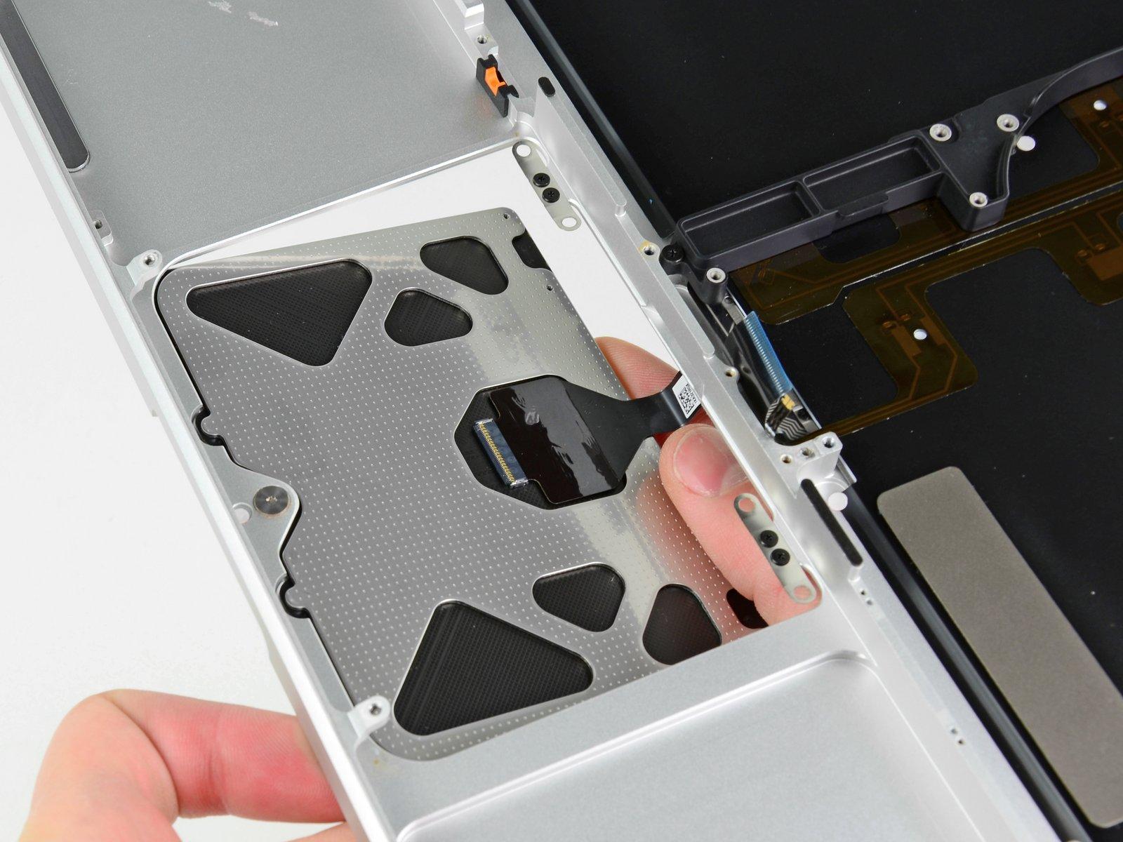
Step 19

– Carefully lift the logic board from the end closest to the optical drive, keeping an eye on those connectors along the edges.
– Gently maneuver the board out of the upper case without bending it, and watch out for that flexible connection to the DC-In board that might try to hitch a ride.
– And voilà, the logic board is free!
Step 20

Keep an eye on those little springs hiding under each screw; they love to play hide and seek!
– Let’s get started! First, grab your trusty screwdriver and remove those three 8.4 mm #1 Phillips screws that are holding the heat sink snugly to the logic board. You’ve got this!
Step 21

Make sure to wipe off that old thermal paste and slather on a fresh layer before putting the heat sink back in place. Check out our guide to make it a breeze!
If the heat sink is feeling a bit clingy, try gently prying it off the processor with a