DIY MacBook Pro 13 Unibody Early 2011 Heat Sink Replacement Guide
Duration: 45 minutes
Steps: 21 Steps
Heads up! Before you dive in, make sure you’ve got a comfy space and all your tools ready to roll. If things get tricky or you’re feeling a bit stuck, don’t hesitate to schedule a repair. We’ve got your back!
Is your MacBook Pro feeling a bit slow and overheated thanks to those hefty blobs of OEM thermal paste? Fear not! This guide will help you tackle that heat sink and refresh your thermal paste like a pro. Let’s get to it!
Step 1

– Time to get those screws out! Let’s tackle the ten screws that are just waiting to be removed. You’ve got this!
Step 2


– Gently wiggle your fingers to pop the lower case away from the MacBook body, right by the vent. You’ve got this!
– Now, go ahead and lift off that lower case.
Step 3


Gently lift up on both shorter sides of the connector to help it ease out of its socket. Just a heads up, the corners of the connectors can be a bit fragile, so handle them with care!
– Gently nudge the battery connector upward from its cozy little home on the logic board using the edge of a spudger. You’ve got this!
Tools Used

Step 4

– Gently nudge the battery cable away from its cozy spot on the logic board to prevent it from making any surprise connections while you work your magic.
Step 5


Check out the fan socket and connector in the second and third pictures! Just a heads up—when you’re using your spudger to gently lift the fan connector straight up and out of its socket, be extra careful not to break off that plastic fan socket from the logic board. The layout in the second picture might look a bit different from your device, but don’t worry, the fan socket is still the same.
Step 6

– Unscrew those three little screws holding the fan tight to the logic board. Let’s get that fan free!
Step 7

– Gently lift the fan out of its cozy spot on the logic board, keeping an eye on its cable so it doesn’t get tangled up.
Step 8


– Grab your trusty spudger and gently coax the right speaker/subwoofer cable out from under the retaining finger that’s snugly molded into the upper case.
– Now, give that right speaker/subwoofer cable a little lift to pop the connector right out of its cozy socket on the logic board.
Tools Used
Step 9

– Unplug the camera cable from the logic board.
Step 10


To unplug the cables, grab your trusty spudger and gently lift their connectors off the sockets on the logic board. You’ve got this!
– Time to unplug those four cables!
Tools Used
Step 11


Just a friendly reminder: make sure you’re gently lifting the hinged retaining flap, not the socket itself. You’ve got this!
– Gently use your fingernail to lift the retaining flap on the keyboard ribbon cable ZIF socket.
– With the tip of a spudger, carefully pull the keyboard ribbon cable out of its cozy socket.
– If the cable is being a bit stubborn, try sticking a piece of tape to it temporarily. It’ll help guide that cable right where it needs to go!
Tools Used

Step 13


Just a friendly reminder: make sure you’re gently lifting the hinged retaining flap, not the socket itself!
– Grab your trusty spudger or just use your fingernail to gently lift the retaining flap on the keyboard backlight ribbon cable ZIF socket. You’ve got this!
– Once the flap is up, carefully pull the keyboard backlight ribbon cable out of its cozy little socket. Easy peasy!
Tools Used
Step 14

– Gently use the flat end of your trusty spudger to lift the sleep sensor/battery indicator connector out of its cozy socket on the logic board. You’ve got this!
Tools Used
Step 15


Hey there! Just a gentle reminder: don’t yank on that display data cable! It’s a bit delicate, and its socket is super fragile. Instead, give it a nice, smooth pull parallel to the logic board’s face. You’ve got this!
– Hey there! First, give that plastic pull tab attached to the display data cable lock a gentle twist toward the DC-In side of your device. You’ve got this!
– Now, with a smooth motion, pull the display data cable right out of its cozy spot on the logic board. Easy peasy!
Step 16

In some models, you might find that the screws are a tad shorter, and that’s totally normal!
– Unscrew those nine little guys right there!
Step 17


– Let’s get started by unscrewing those two pesky screws!
– Next up, gently take out the display data cable retainer from the upper case. You’re doing great!

Step 19

– Carefully lift the logic board from the side closest to the optical drive, keeping an eye on all those little connectors hanging out near the edges.
– Gently wiggle it out of the upper case without bending the board. Just be cautious of the flexible connection to the DC-In board—it might want to stick around in the upper case.
– And voilà! You’ve successfully removed the logic board.
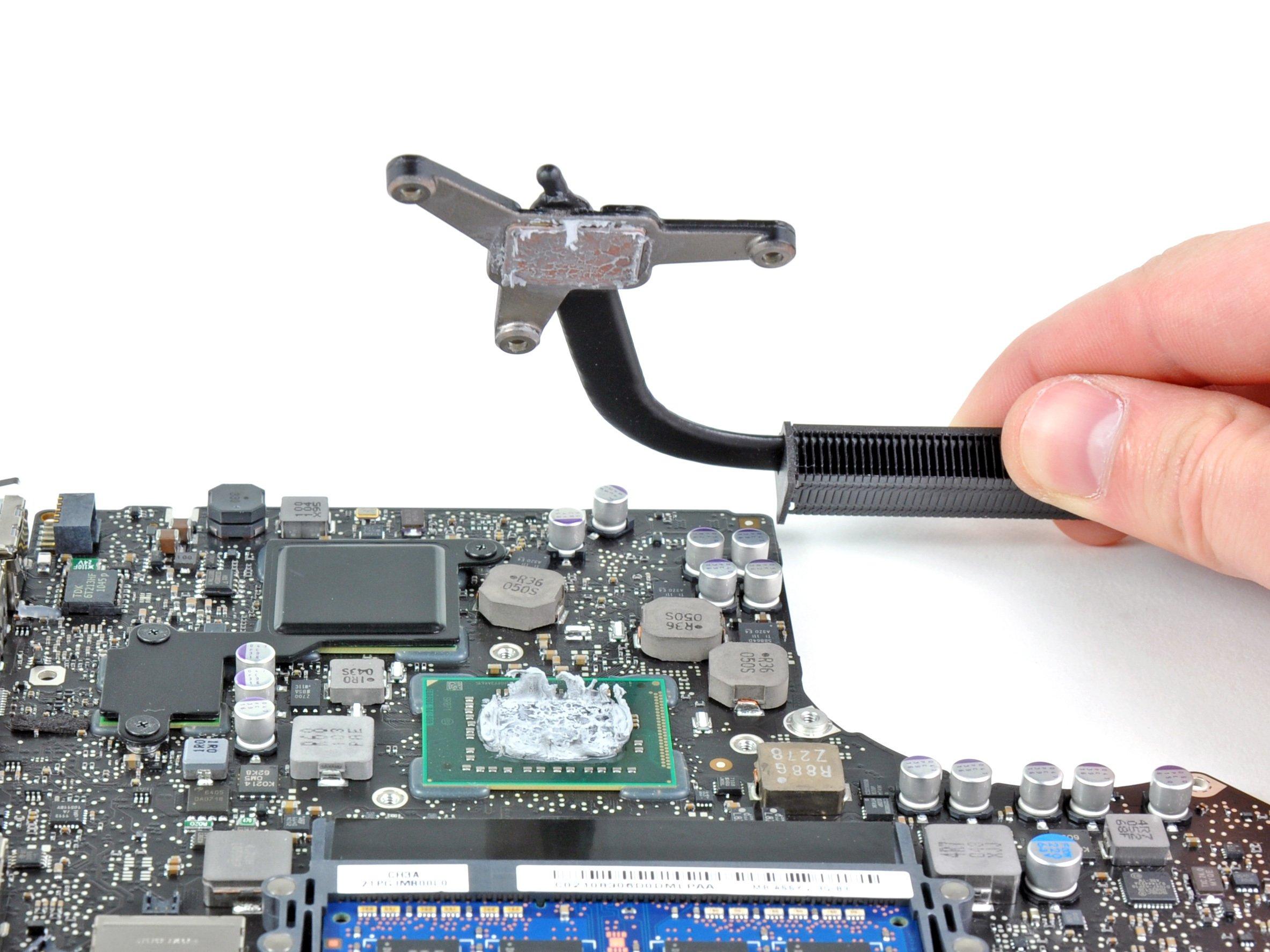
Step 20

Make sure to keep those little springs safe that are tucked under each screw. They’re important buddies for your device!
– Let’s tackle those pesky screws! Grab your trusty #1 Phillips screwdriver and remove the three 8.4 mm screws holding the heat sink snugly against the logic board. You’ve got this!
Step 21

Don’t forget to wipe off that old thermal paste and slather on a fresh layer before you put the heat sink back in place. We’ve got a handy guide to help you with it!
If the heat sink is feeling a bit stubborn, try gently coaxing it off the processor with a