MacBook Pro 13″ Unibody Mid 2010 Microphone Replacement
Duration: 45 minutes
Steps: 21 Steps
Hey there! Just a friendly reminder to keep your workspace tidy and organized while you tackle this repair. A clean area helps you focus and keeps everything in one place. And remember, if you ever feel stuck or need a hand, you can always schedule a repair. You’ve got this!
Ready to tackle that pesky blown-out microphone? Dive into this guide and let’s get that sound back on track! If you need help, you can always schedule a repair.
Step 1

– Time to get your hands busy! Start by unscrewing the 10 screws that are holding down the lower case of your MacBook Pro 13″ Unibody. You’ve got this!
Step 2

– Gently lift the lower case and slide it towards the back of the device to release those pesky mounting tabs.
Step 3

Just a friendly reminder: it’s a great idea to unplug the battery connector from the logic board before diving in. This helps keep any electrical surprises at bay while you work your magic!
– Grab that trusty spudger and gently nudge the flat end under the battery connector. Give it a little lift to pop it out of its cozy socket on the logic board. You’ve got this!
Tools Used

Step 4


Check out the second and third pictures to spot the fan socket and the fan connector. Remember, you’re on a mission here—so be gentle with that plastic fan socket on the logic board! Use your trusty spudger to carefully lift the fan connector straight out of its cozy socket. The layout of the logic board in the second picture might look a bit different from your device, but no worries—the fan socket is just the same.
A little twist with the spudger from under the fan cable wires can work wonders to pop that connector loose!
– Gently use a spudger to lift the fan connector out of its cozy socket on the logic board. You’ve got this!
Step 5

– Time to take off those screws! Go ahead and remove the three screws listed below:
Step 6

– Gently lift the fan out of the upper case, like you’re giving it a little hug as it makes its exit!
Step 7


– Give that plastic pull tab a gentle tug and swing it toward the DC-In side of your computer like you’re opening a party favor.
– Now, carefully slide the display data cable connector away from the board, keeping it nice and parallel. You’re doing great!
Step 8


– Unscrew those two screws holding down the display data cable bracket to the upper case – you’re almost there!
– Gently lift that display data cable bracket out of the upper case. You’ve got this!
Step 9

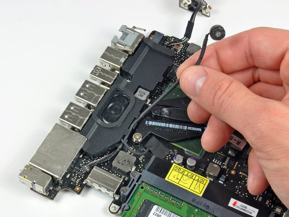
– Gently slide the flat end of your trusty spudger underneath the subwoofer and right speaker connector, and give it a little lift to pop it off the logic board. You’ve got this!
Tools Used
Step 10

This socket is made of metal and is a bit flexible, so handle it with care! Make sure to line up the connector perfectly with its socket on the logic board before joining them together. You’ve got this!
– Gently tug the camera cable connector toward the optical drive to free it from the logic board. You’re doing great!
Step 11


– Gently use the flat end of a spudger to lift the optical drive, hard drive, and trackpad cable connectors off the logic board. You’ve got this!
Tools Used


Step 13

– Gently remove the little strip of black tape that’s holding down the keyboard backlight ribbon cable socket. You’ve got this!


Step 15

– Gently use the flat end of a spudger to lift the battery indicator cable connector off the logic board. You’ve got this!
Tools Used
Step 16

– Grab your trusty spudger and gently nudge the microphone away from its sticky home on the upper case. You’ve got this!
Tools Used
Step 17

– Unscrew the following screws:
Step 18


While it’s not absolutely necessary to remove the battery before taking out the logic board, doing so definitely makes the job smoother and safer. If you decide to keep the battery in, just be extra careful not to bend the logic board against the battery case near the bar code. You’ve got this!
– Unscrew those pesky Tri-point screws holding the battery snugly in the upper case: it’s time to set it free!
– Gently lift the battery out of its cozy home in the upper case. You’ve got this!
Step 19


– Gently lift the logic board by its left edge and raise it until those ports can happily wave goodbye to the side of the upper case.
– Now, with a little finesse, pull the logic board away from the upper case, making sure to keep an eye on the DC-In board so it doesn’t get stuck along the way.
Step 20

– Gently peel away the tape that’s guarding the microphone cable connector.
Step 21

– Gently slide the flat end of a spudger under the microphone cable connector and lift it off the logic board with a little finesse.
– Carefully guide the microphone cable out of the channel in the left speaker. You’ve got this!
Tools Used
