DIY Guide to Remove Logic Board from Fairphone 2
Duration: 45 min.
Steps: 22 Steps
In this guide, we’ll walk you through the process of removing the PCB from your Fairphone 2 all by yourself! If you’re looking to give your logic board a good clean, this is the step you need to take. Let’s get started!
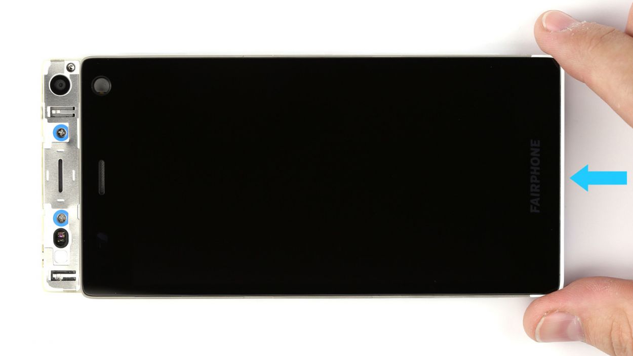
Step 1

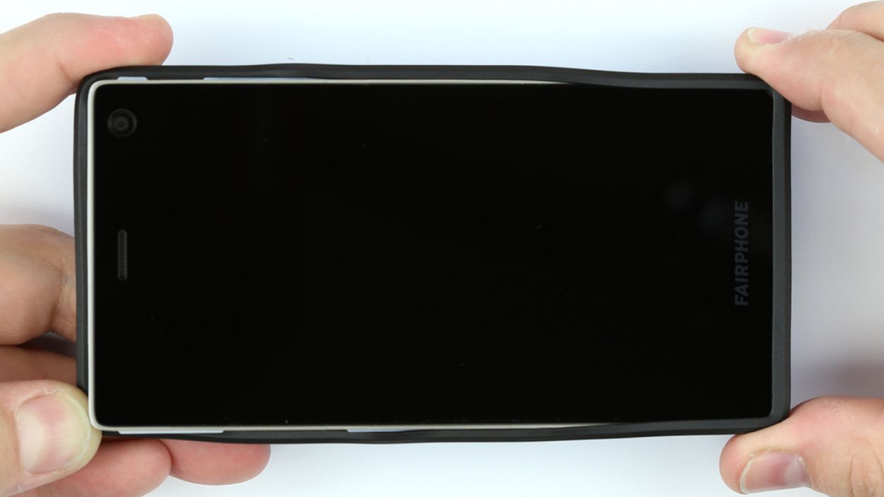
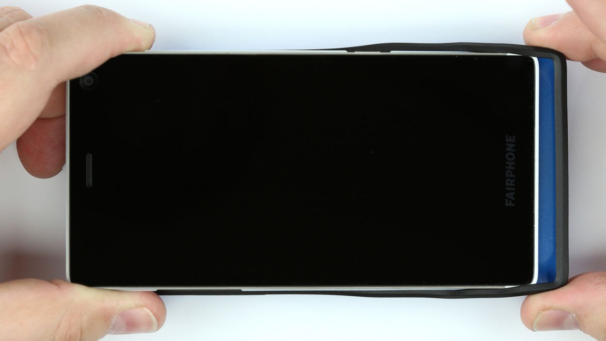
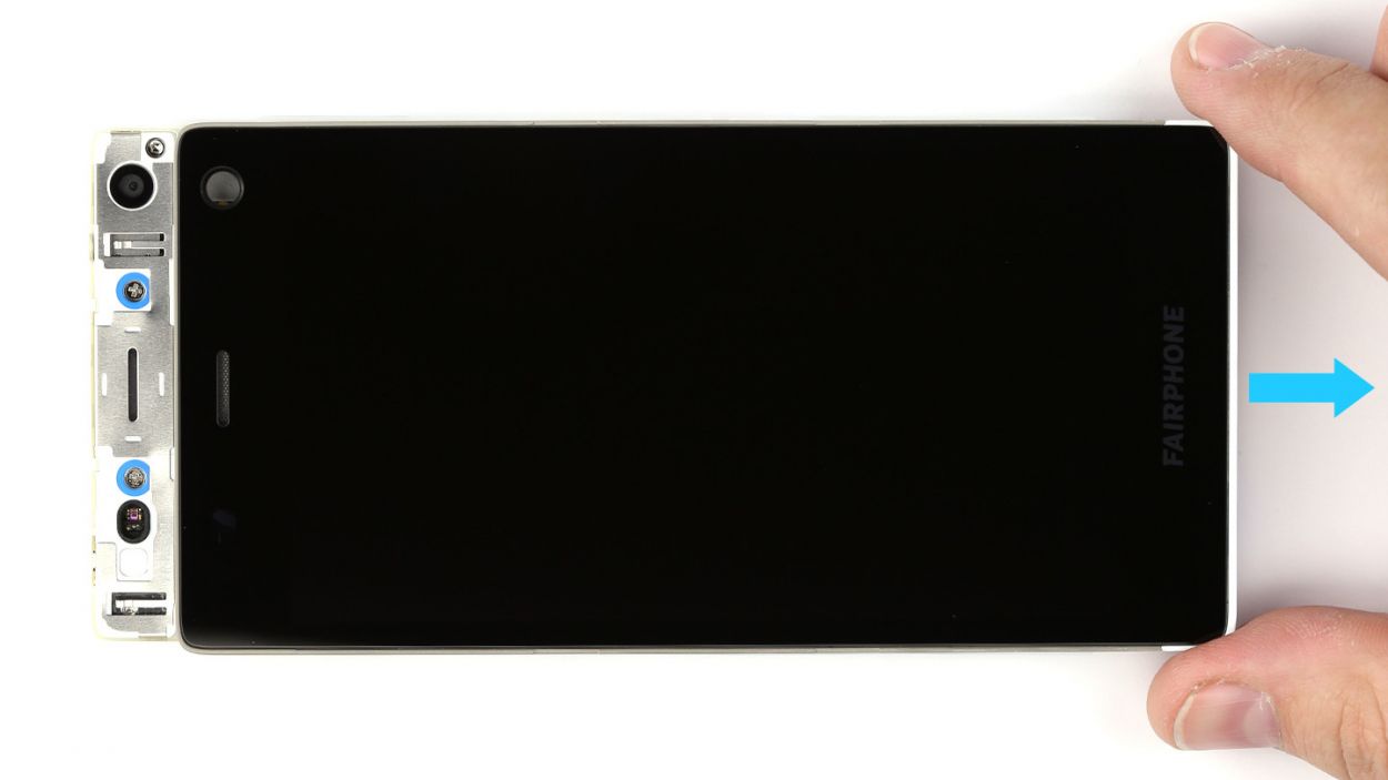
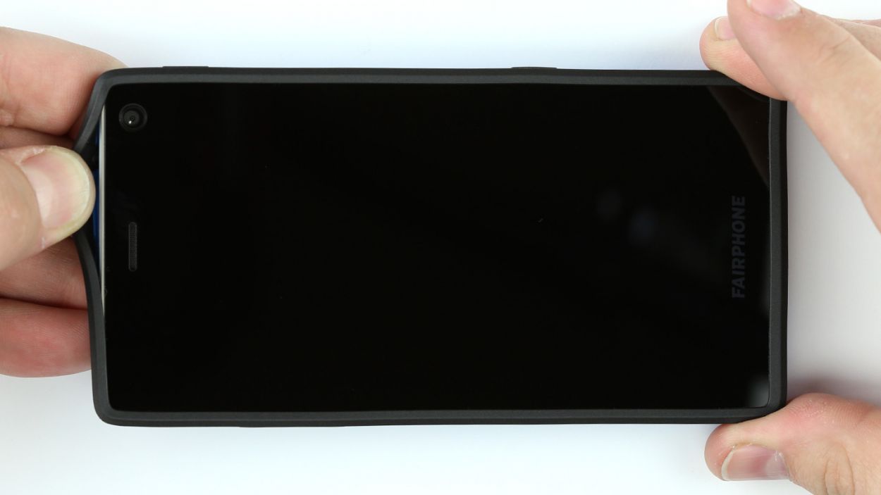
– Pull on the back cover’s rubber rim on one of the short sides of your Fairphone, and pull the cover off one corner of the device. It’s easy to get your fingernails under the rubber rim.
– Pull the back cover off the next corner of your device.
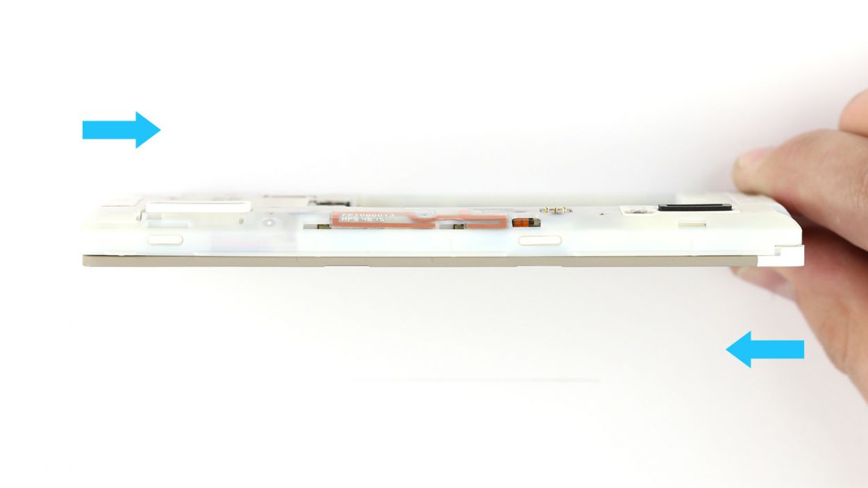
– Remove your Fairphone from the enclosure.
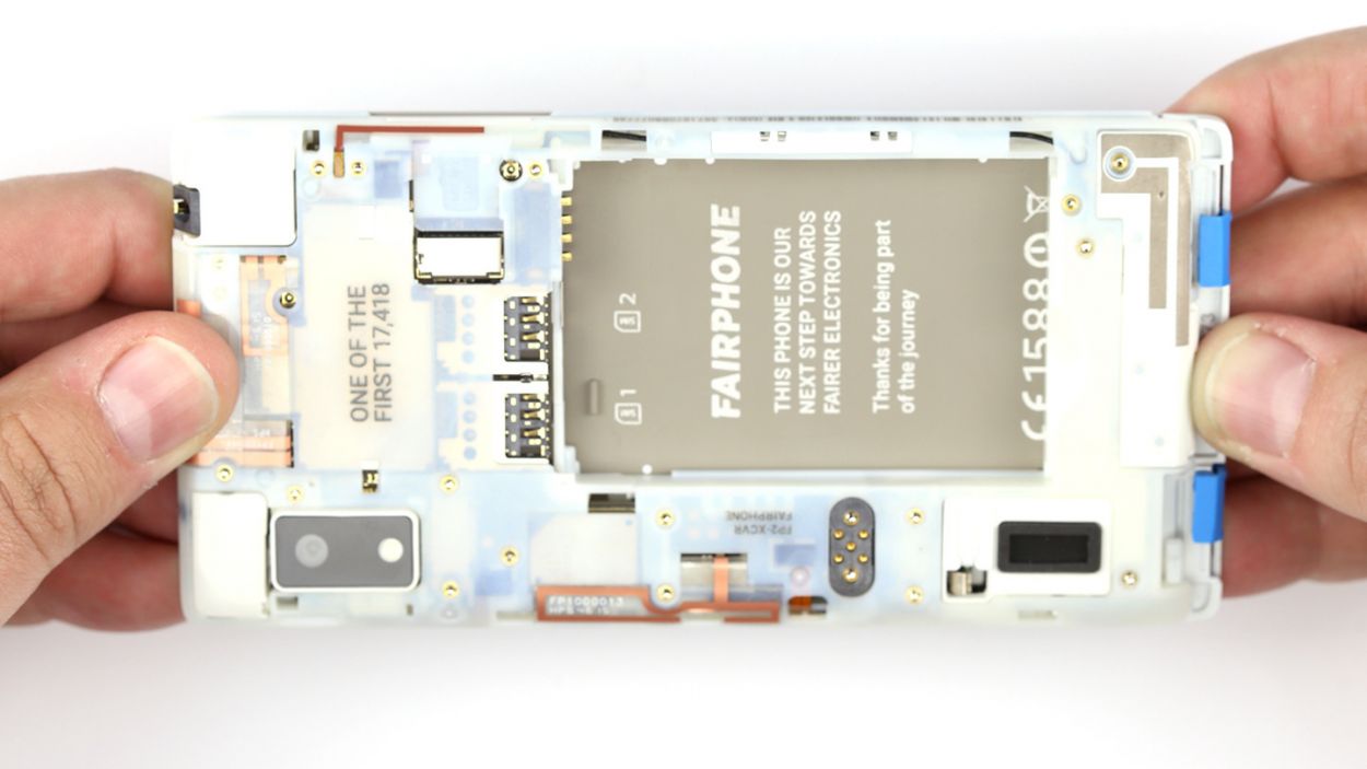
Step 2

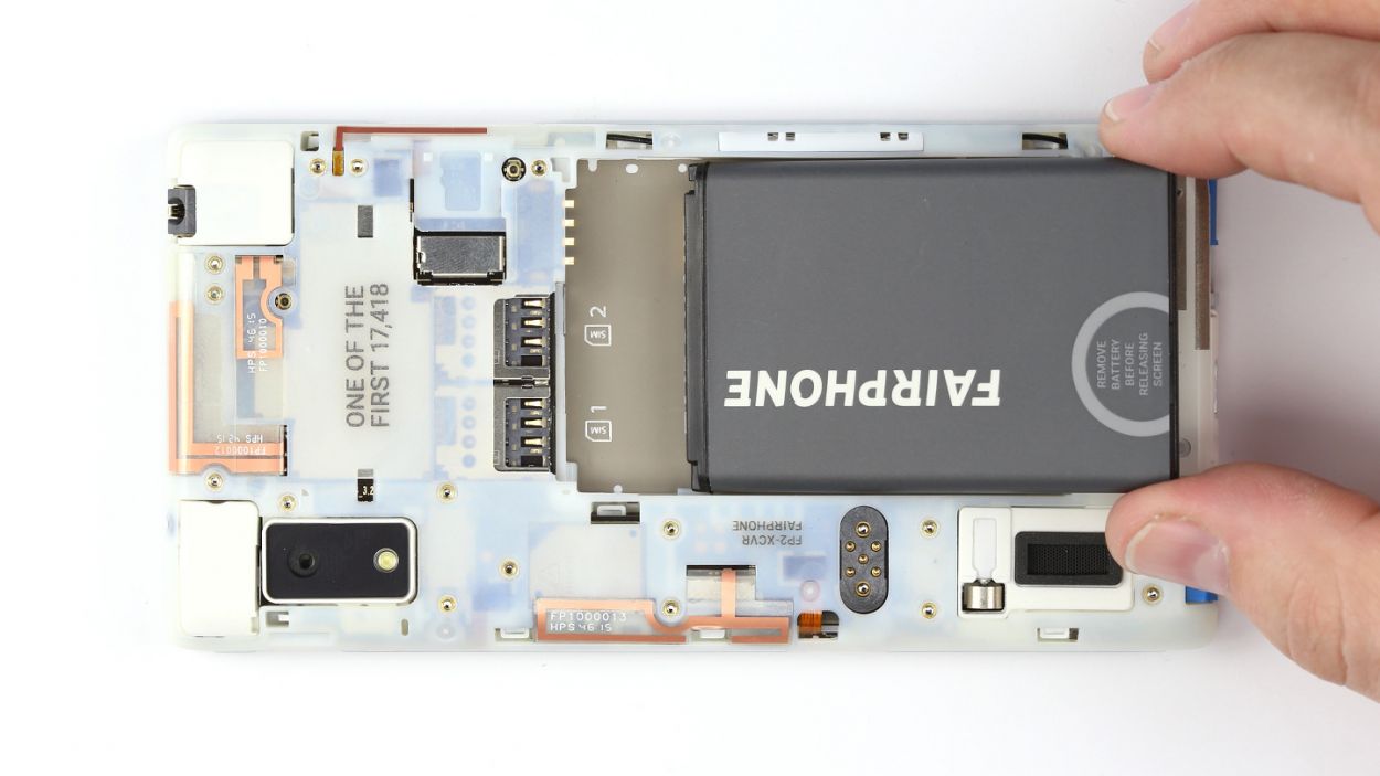
– Lift the battery out of the chassis.
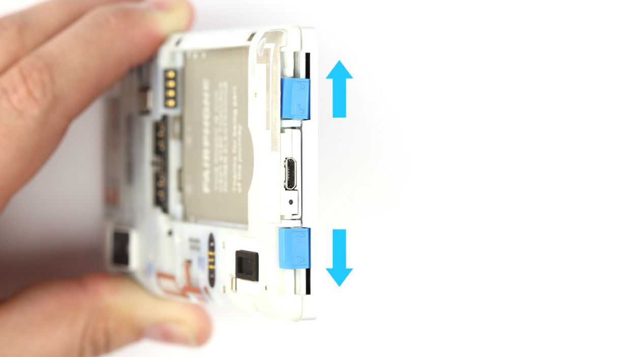
Step 3

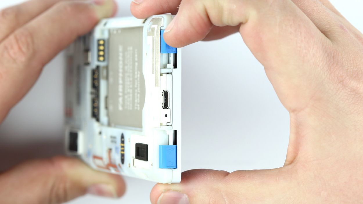
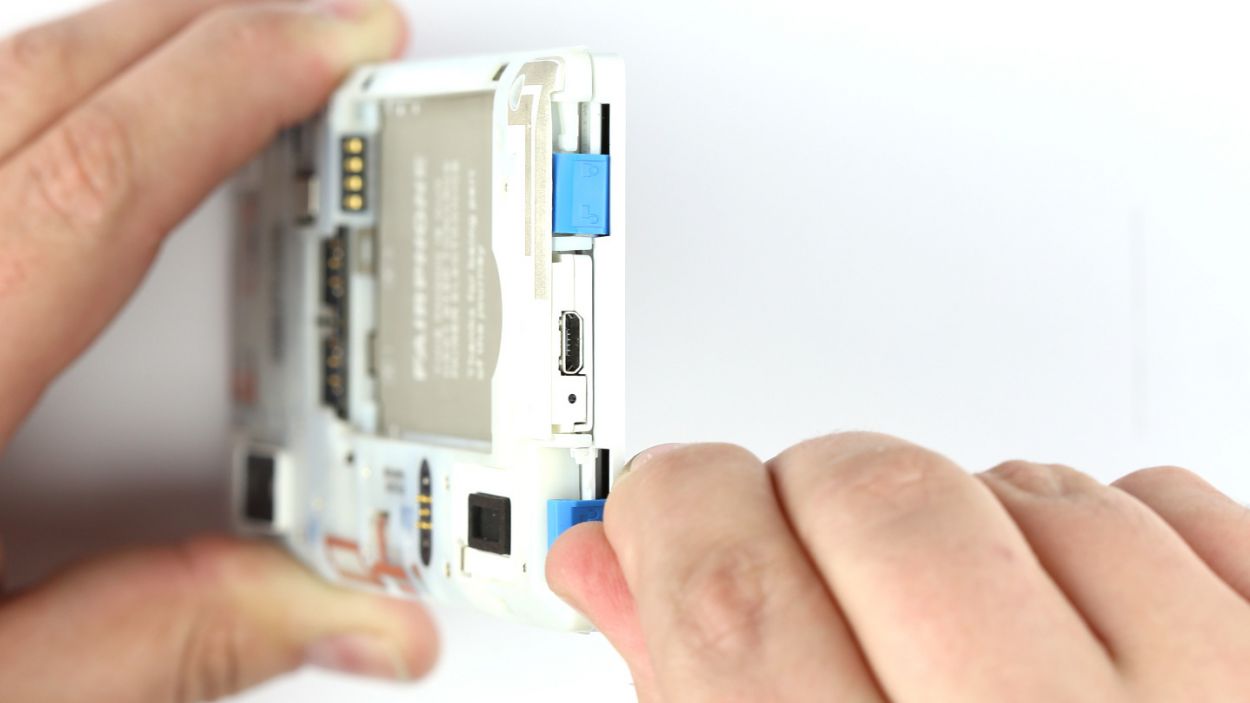
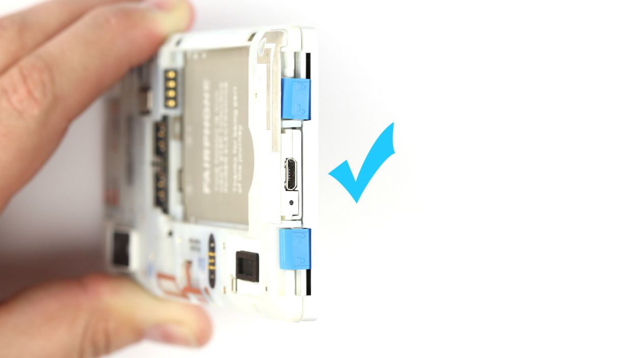
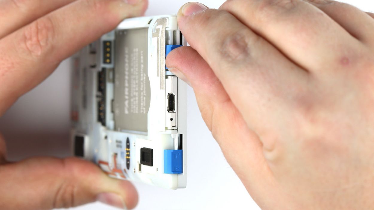
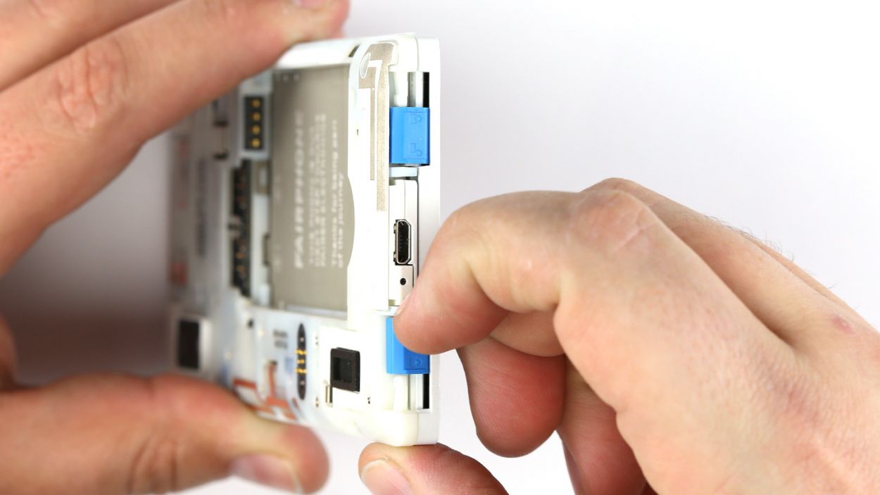
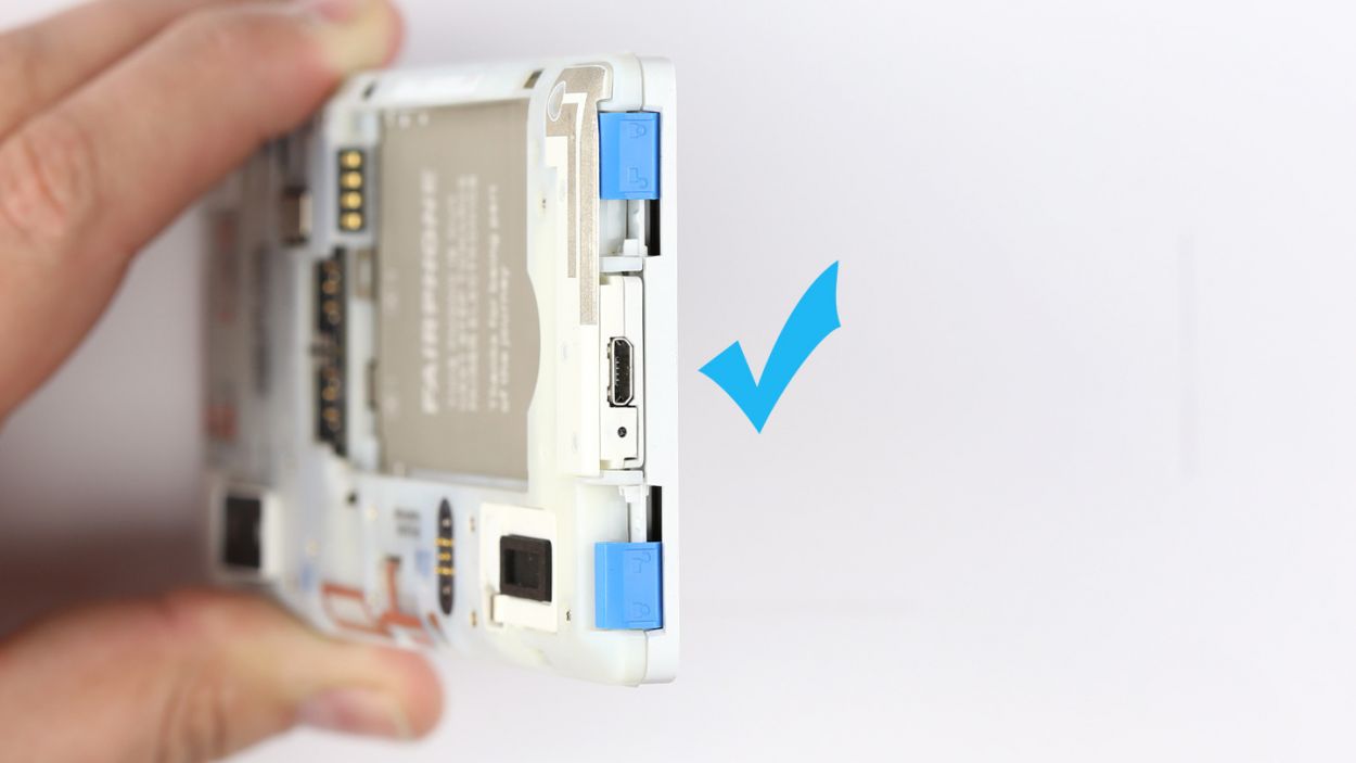
– At the bottom of your Fairphone 2, you’ll find two little locks holding the display module snugly to the chassis. Just give those sliders a friendly nudge toward the Micro-USB port to set them free.
– Make sure to release those locks one at a time, and you’re on your way!

Step 5
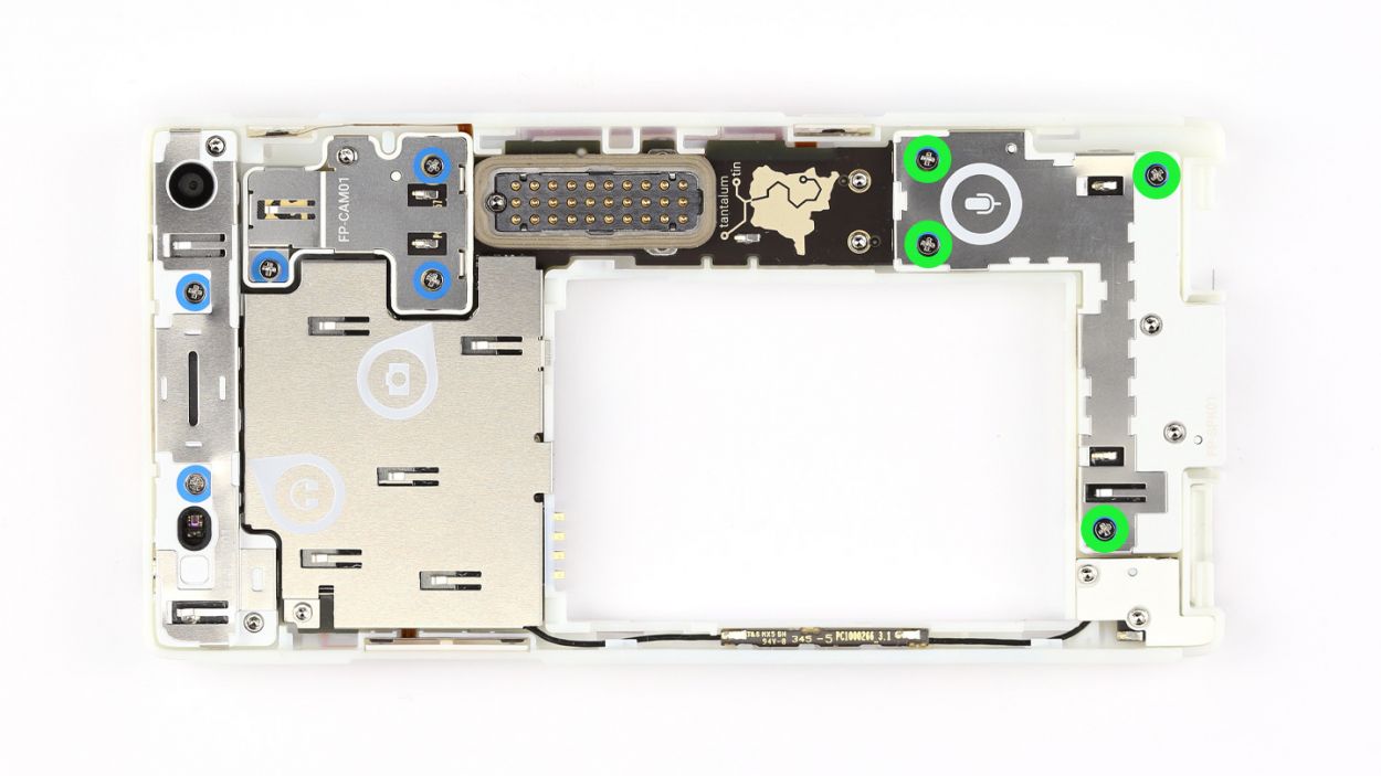

– First things first, grab your trusty Phillips screwdriver and take out those four screws holding the module snugly in place. We’re talking about 4 x 5.5 mm Phillips screws here!
– Now, gently lift out the microphone/USB module and keep it safe with the screws. You’re doing great!
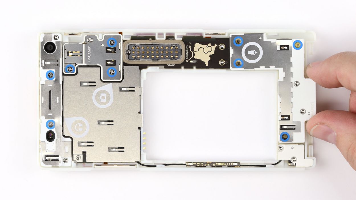
Step 6
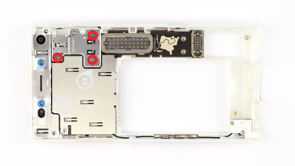
– First up, grab your trusty screwdriver and take out those three Phillips screws holding the camera module snugly in place. We’re talking about 3 x 5.5 mm Phillips screws here!
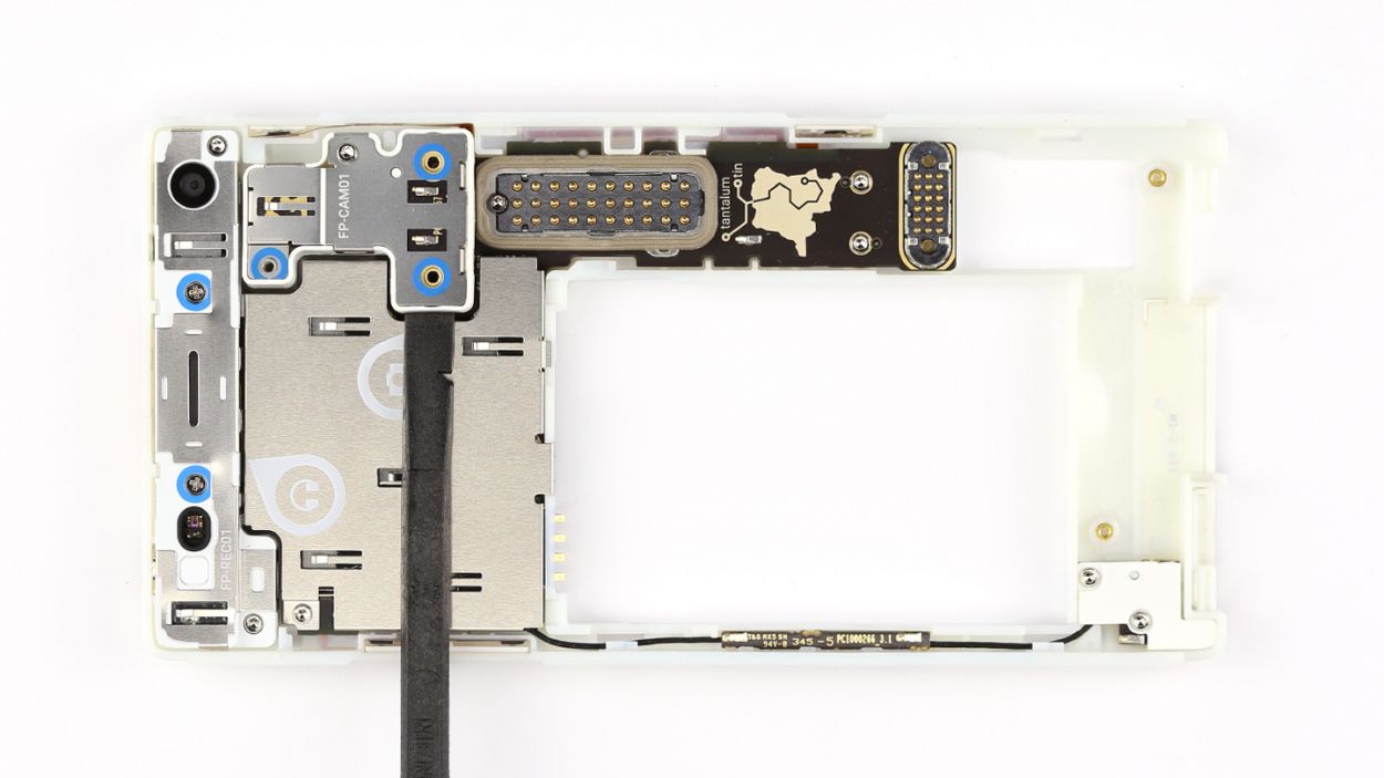
– Next, it’s time to get a little crafty! Use the flat end of your spudger to gently pry the module out. You’ve got this!
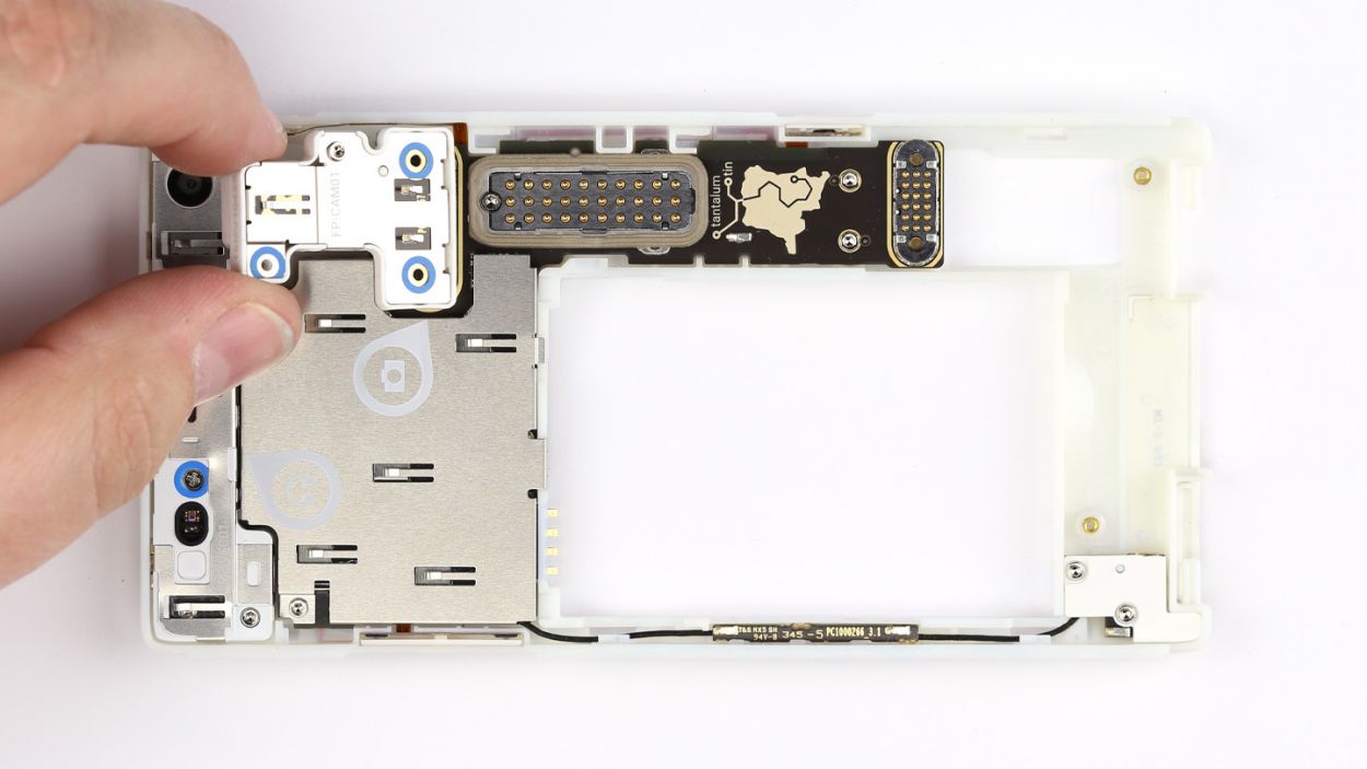
– Finally, carefully lift out the camera module and keep it safe with those screws. You’re doing great!
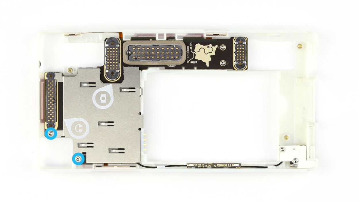
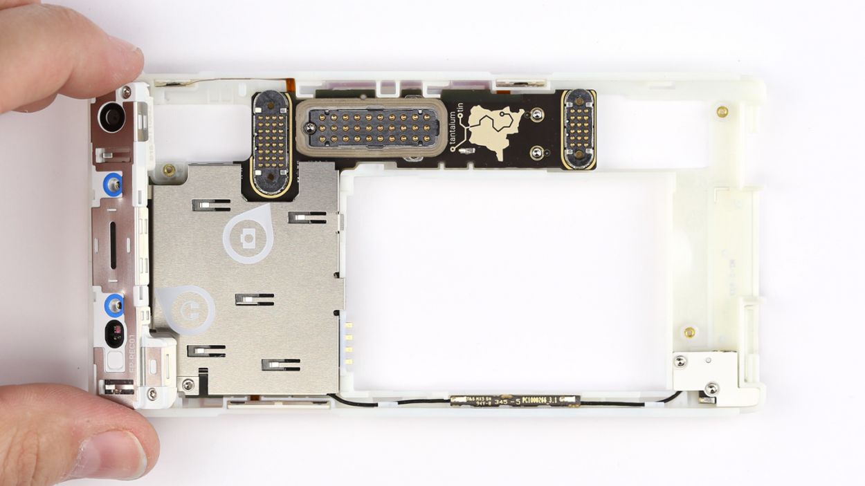
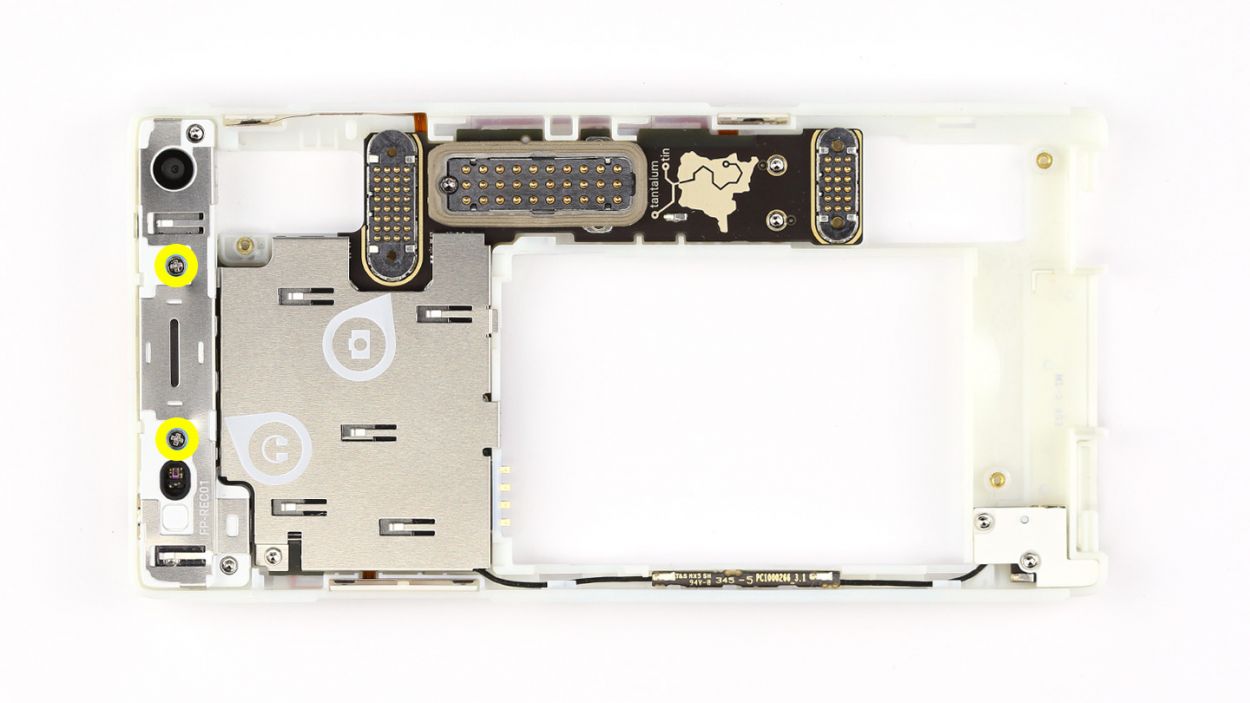
Step 7


– Remove the two Phillips screws that hold the module in place.2 x 5.5 mm Phillips screws
– Push the module out of the chassis from the back. First press the surface next to the rear camera.
– Then press the surface with the headphone jack.
– Remove the audio module and put it with the screws.
Step 8


– First up, grab your trusty Torx screwdriver and take out those two Torx screws holding the cover plate snugly in place. We’re talking about 2 x 3.3 mm T5 Torx screws here!
– Next, it’s time to whip out your steel laboratory spatula. Use it to gently pop off the cover plate’s retaining clip. You’ve got this!
– Now, carefully lift off the cover plate. Just a heads up, two of the plate’s tabs are hiding below the connector for the audio module, so keep an eye out for them!
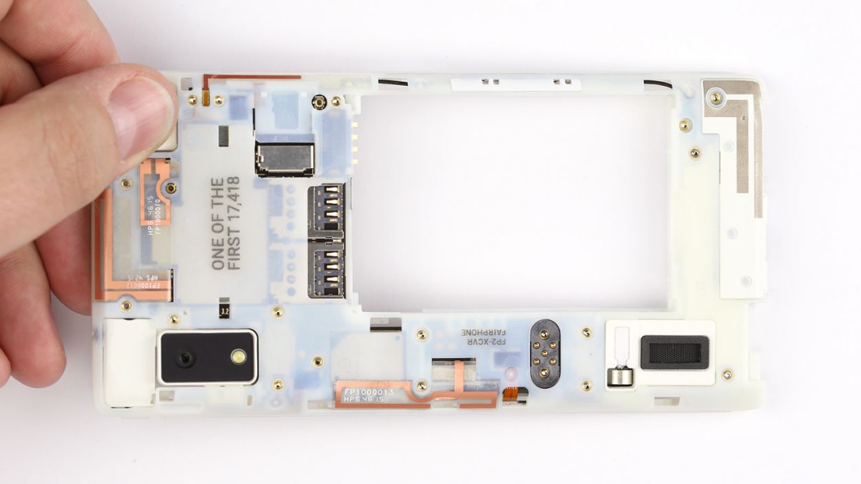
Step 9
– Time to get your hands a little messy! Start by gently unplugging the main antenna from the logic board with the spudger’s pointed tip – you’ll be a pro in no time.
– Next up, it’s screw removal time! Take out those five Torx screws that are keeping the logic board snug and secure: 4 of them are 3.3 mm T5 Torx and 1 is a 4.5 mm T5 Torx screw (the black one). Let’s get that board free!
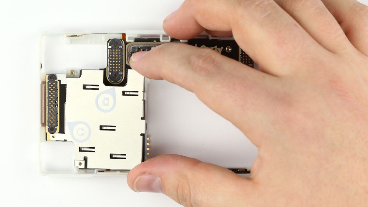
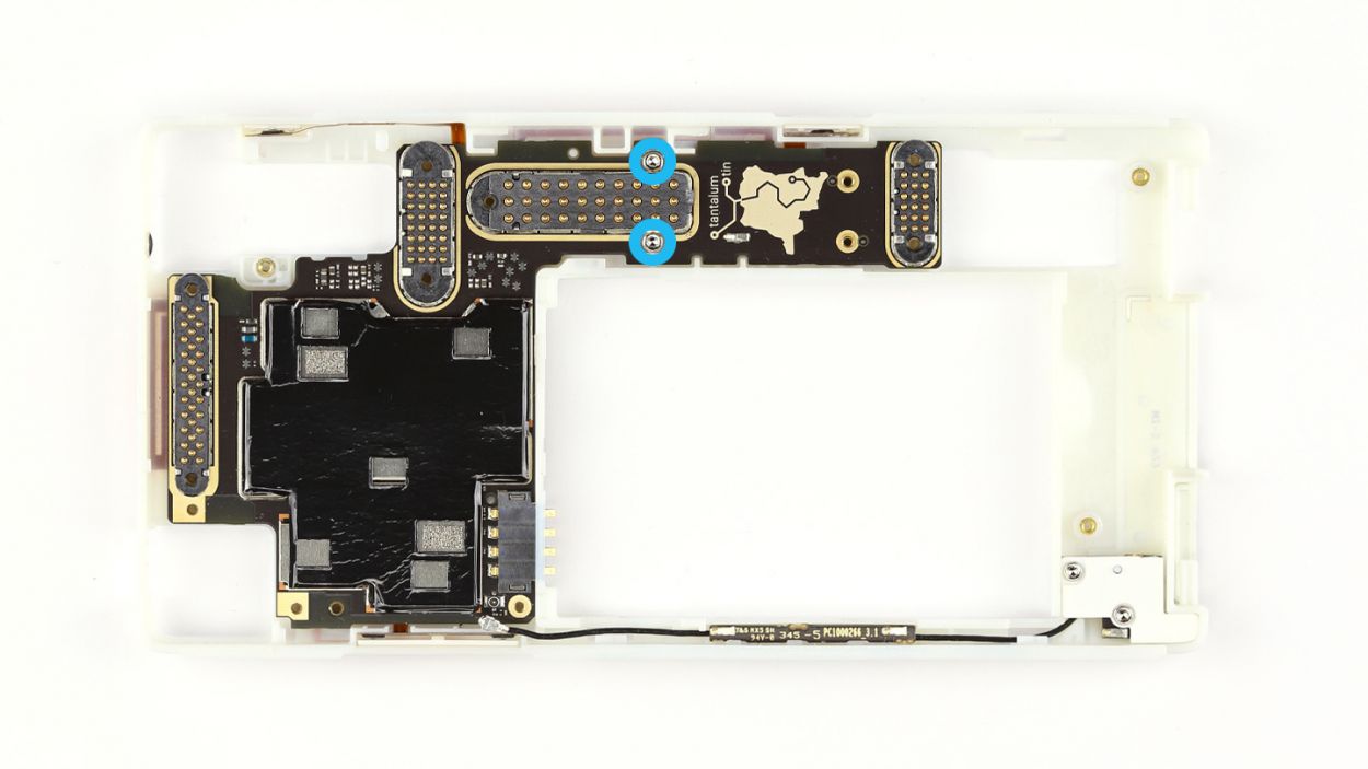
Step 10
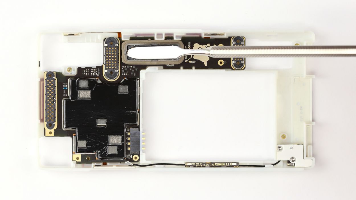


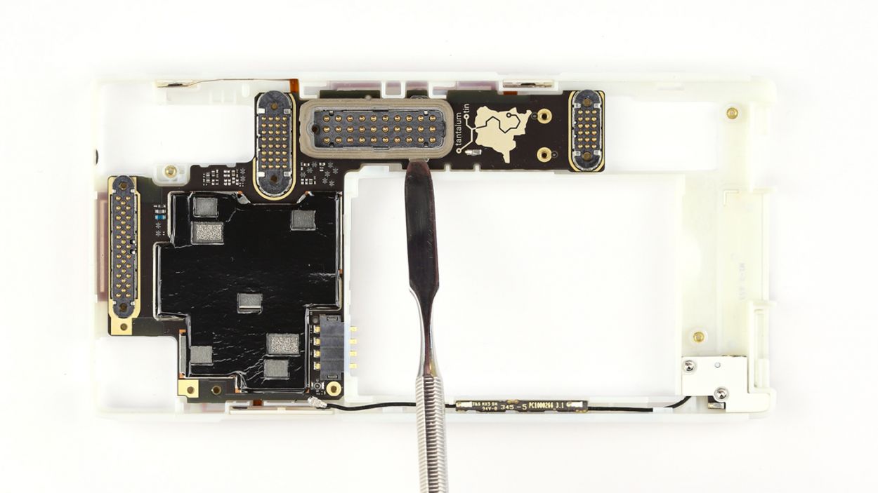
– Grab your trusty steel spatula and gently wiggle it between the display connector and the seal to get things started. You’re on the right track!
– Now, give that seal a little nudge from the other side and pop it out like a pro.
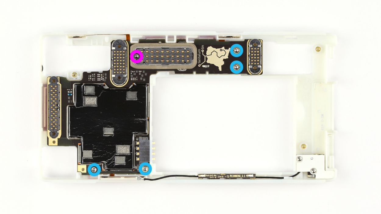
– Time to tackle those pesky Torx screws! Remove the two 3.3 mm T5 Torx screws that are keeping the logic board snug as a bug.
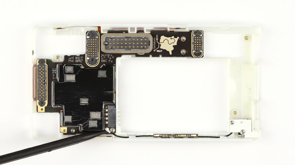
Step 11
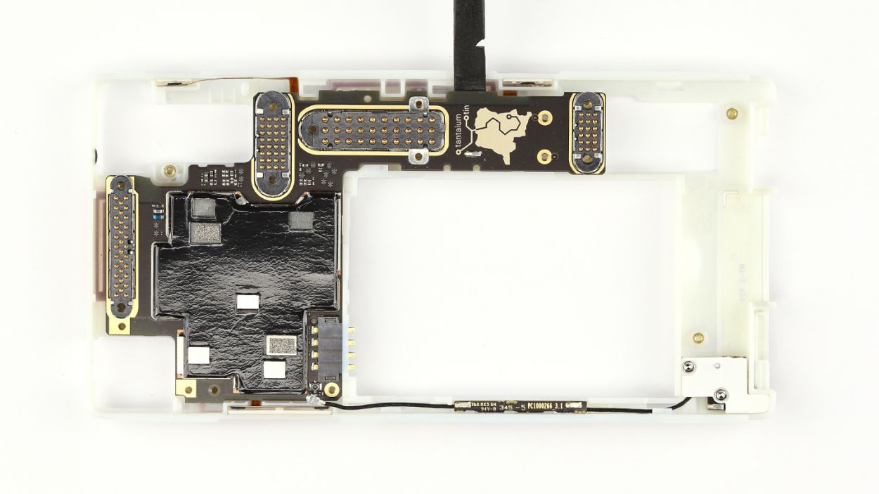
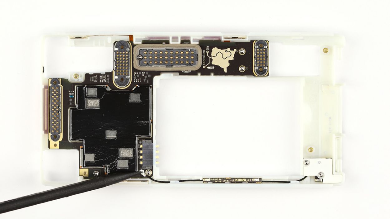
– Disconnect the logic board from the chassis by using the flat end of the spudger to pry it out of the logic board.
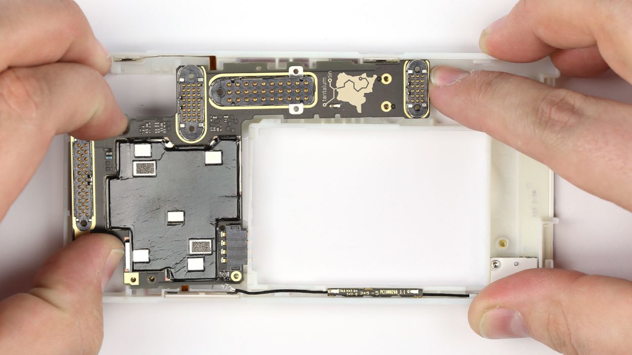
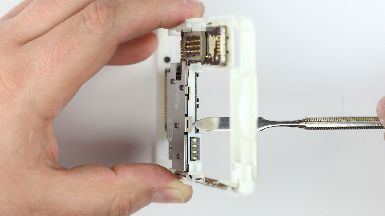
– Lift the logic board with your fingers and move it so the battery connector slides out of the chassis.
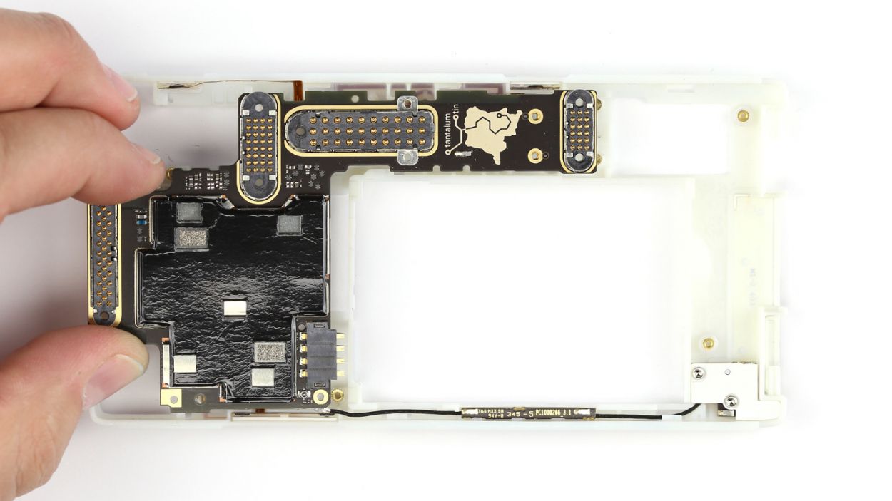
– Lift the logic board out of the chassis.
Step 12


– Gently place the logic board into the chassis, making sure it fits snugly.
– While you’re at it, carefully guide the battery connector into its designated spot in the chassis.
Step 13
– Secure that logic board like a boss with those two sleek Torx screws. We’re talking 2 x 3.3 mm T5 Torx screws, so get ready to tighten things up!
– Now, let’s give that seal another chance to shine on the connector. Position it carefully, and watch the magic happen!
Step 14

– Secure the logic board in place with five Torx screws: four 3.3 mm T5 Torx screws and one 4.5 mm T5 Torx screw (the black one).
– Connect the main antenna to the logic board using the sharp end of the spudger. You’ve got this!
Step 15

– Let’s get that cover plate back on the logic board! Slide those two tabs right under the audio module connector like a pro.
– Give a little push to ensure the plate’s retaining clip snaps into place. You got this!
– Now, secure the cover with those two Torx screws. Remember, we’re using 2 x 3.3 mm T5 Torx screws here. Tighten them up and feel accomplished!
Step 16
– Position the audio module in the chassis. Make sure that it clicks into place under the two tabs on the chassis.
– Fasten the module with the two Phillips screws.2 x 5.5 mm Phillips screws
Step 17


– Gently place the camera module in its cozy spot within the chassis.
– Secure the module using the trio of trusty Phillips screws (3 x 5.5 mm).
Step 18

– Position the microphone/USB module in the chassis.
– Fasten the module with the four Phillips screws.4 x 5.5 mm Phillips screws
Step 19
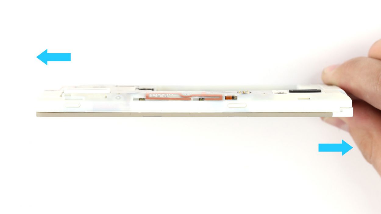
– Put the display on the chassis.
– You can push on the display to connect it to the chassis.
– Push the display module toward the front camera.
Step 20
– Hey there! Two tiny locks are chillin’ at the bottom of your Fairphone 2, holding the display to the chassis. Give those sliders a nudge – push ’em away from the Micro-USB port to unlock!
– Sweet! Now, fasten those locks one at a time. You got this!
Step 22


– Put the Fairphone in the back cover lengthwise. The device can click into place in two corners of the back cover.
– Pull the back cover’s rubber rim over one corner.
– Pull the rubber rim over the last corner. Check whether the rubber rim is on evenly all around the display.


