DIY Guide to Replace Google Nexus 5 Front Camera
Duration: 30 min.
Steps: 15 Steps
Ready to get your LG Google Nexus 5’s front camera back in action? In this guide, we’ll walk you through the steps to swap out that faulty front camera yourself. If your selfies are coming out blurry, the aperture refuses to open, or the camera seems to be on strike, it’s time for a change! Let’s dive in and get your device snapping clear pics again. And remember, if you need help, you can always schedule a repair.
Step 1
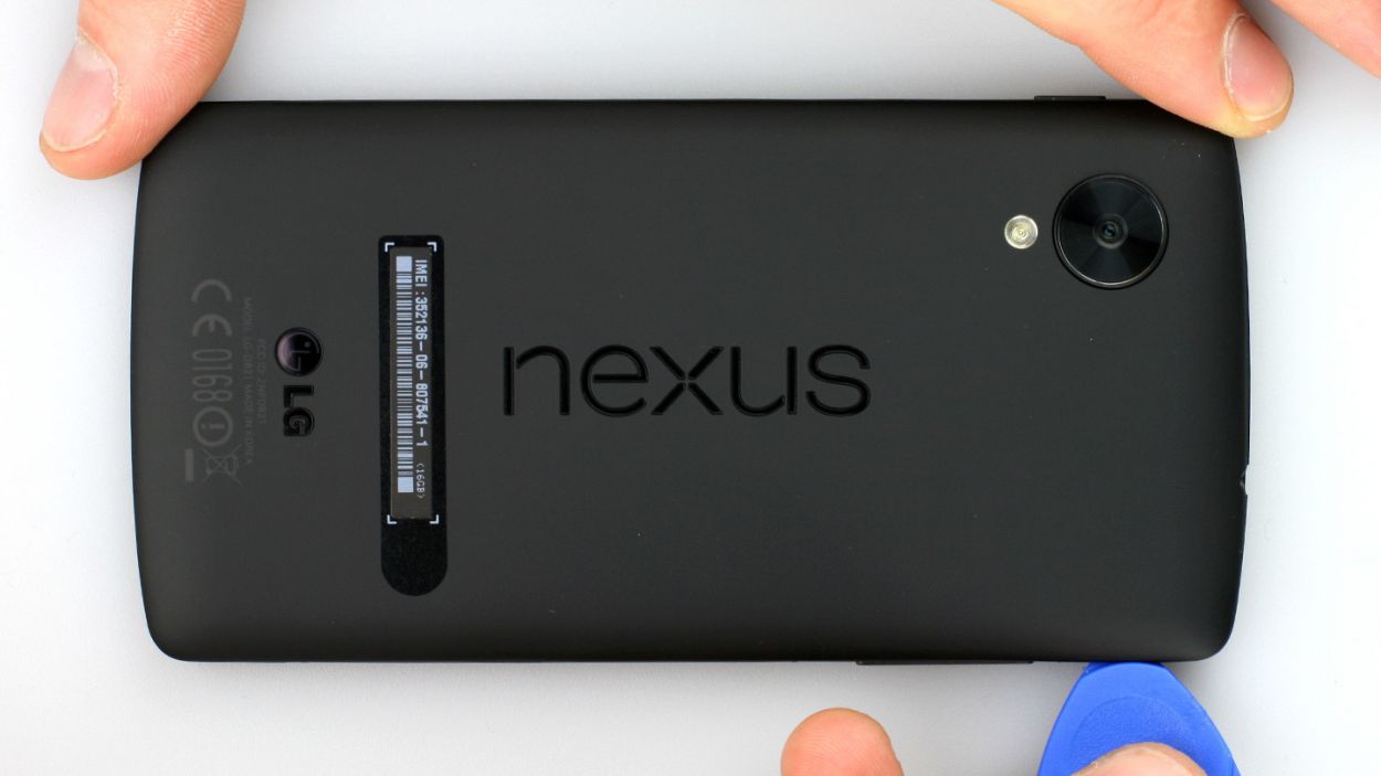
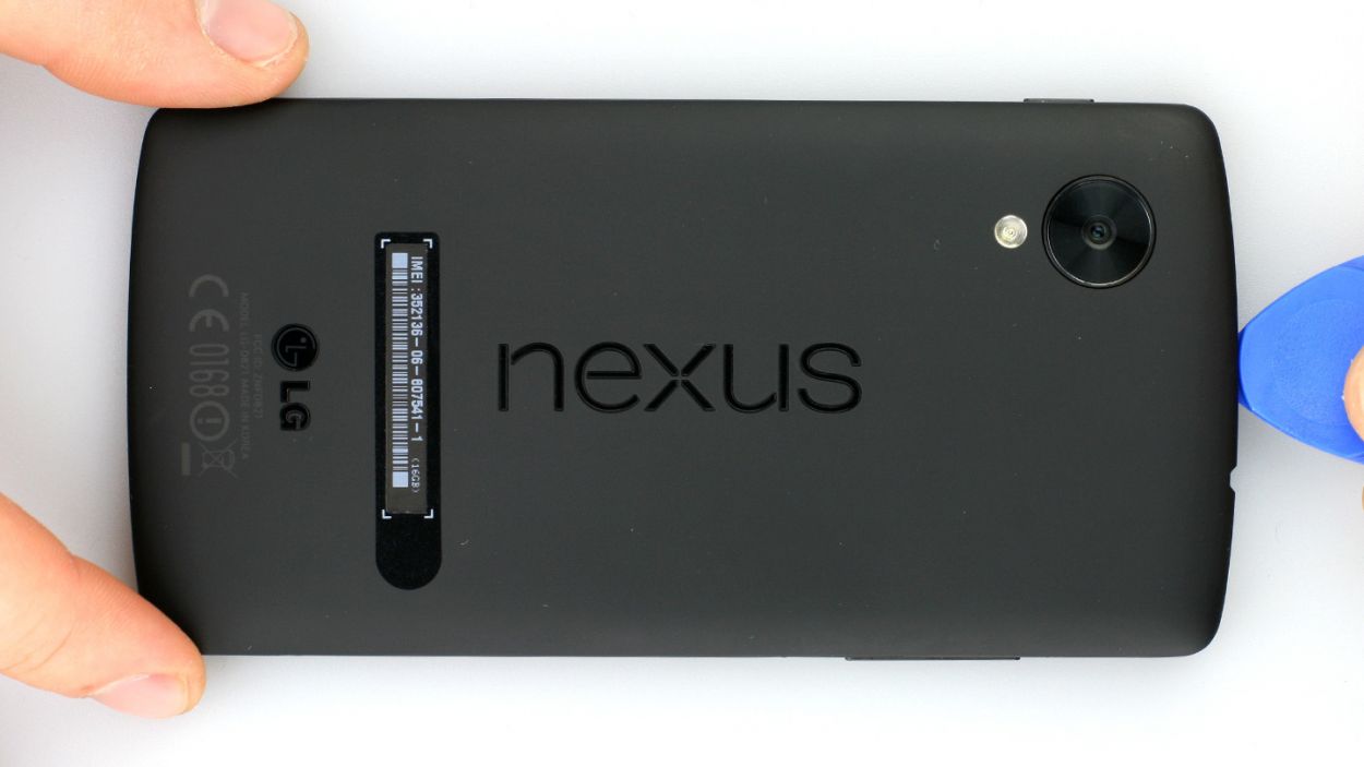

– Alright, let’s get this party started! Gently slide a plastic opening tool into the gap by the volume button. Unclip those 18 tiny (but tenacious!) clips holding the back cover on. Wiggle that tool all the way around the phone – think of it as a phone-hugging dance! Start at the volume button, groove past the headphone jack, and then waltz on over to the SIM card tray. It’ll pop off easier there. You might need a little extra oomph in some spots.
– And there you have it! The back cover is ready to come off. High five! If you need a hand, you can always schedule a repair.
Step 2
– First up, let’s tackle those 6 Phillips screws holding the plastic cover snugly in place (check out figure 1 for a visual!). We’re talking about 6 x 4.0 mm Phillips screws here, so grab your trusty screwdriver and get to work!
– Once those screws are out of the way, gently lift the cover off the logic board. You can use a spudger to slide into the gap next to the headphone output (figure 2 has your back here). If you need a little extra leverage, feel free to explore other points to help you out!
Step 3
– Grab your trusty SIM Tool or a simple paperclip to pop that SIM card tray right out! Just gently press the tool into the little hole on the tray, and watch it come free. Easy peasy!
Step 4
– That headphone jack is feeling a little snug in its plastic home! Gently nudge the pointed end of your spudger into the jack and give it a little lift. Easy peasy!
Step 6
LCD
USB port
Battery
Front camera
Rear camera
4 × Antenna
Be super careful not to accidentally snap off those little resistors that are happily soldered onto the logic board. We want them to stay put!
– Alright, it’s time to gently disconnect those highlighted connectors! Just a friendly reminder to be super careful (check out figure 1). We definitely don’t want to accidentally break off those little resistors that are snugly soldered onto the logic board.
– Now, grab your trusty spudger and place the flat end just a smidge below the connectors. Give them a gentle pry to pop them off. The pictures will guide you on where to position the spudger to keep those tiny resistors safe, even if it slips (see figures 2 to 6).
– And don’t forget to disconnect those tiny antenna connectors from the logic board as well (see figures 7 and 8). You’ve got this!
Step 7
– Time to channel your inner tech wizard! Gently lift that logic board with your trusty spudger (check out figure 1). Slide the flat end under the GPS antenna’s contacts, give it a little lift, and then gracefully remove it by hand (see figure 2). You’ve got this!
Step 8
– Use the tweezers or your fingers to lift the camera at the connector. It’s still connected to the plastic frame from above by an adhesive strip. The end of the adhesive strip is hidden below a piece of rubber coating, but this rubber coating is easy to lift.
– Now remove the front camera.
Step 9
– Let’s get that front camera back home where it belongs, yeah!
– Time to give it a little hug by securing that adhesive strip back where it belongs.
Step 10
– Carefully put the logic board back in, making sure it’s in the right position.
– Make sure the antenna connectors don’t get under the logic board.
Step 11
LCD
USB port
Battery
Front camera
Rear camera
4 × Antenna
– Give the contacts a high-five, make sure they’re nice and cozy in their new spot. Don’t go overboard with the finger power, just a gentle nudge and they’ll give you a happy little click.
– If you’ve got antenna connectors waiting to join the party, give them a warm welcome too.
Step 12
– Now put the earpiece back in the appropriate position. The adhesive strip should still be sticky enough.
Step 13
– Now put the new headphone output in the appropriate position. Carefully press on the part between the earpiece and the logic board. This step is a bit tricky.
Step 14
– Put the black plastic cover on the logic board and gently press it on.
– Fasten the 6 Phillips screws that hold the cover in place again.6 x 4.0 mm Phillips screws
Step 15
– It’s very easy to put the back cover back on. Put it on in the correct position and press it on all the way around until it’s completely clicked into place.