How To Replace OnePlus One Screen: Step-by-Step Guide
Duration: 75 min.
Steps: 22 Steps
In this guide, we’re here to help you swap out that pesky display unit on your OnePlus One. If your screen is cracked, the touchscreen is playing hard to get, or the LCD is stuck in a black hole or flickering like a disco ball, it’s time for a change! If you need help, you can always schedule a repair.
Step 1
– Get your OnePlus One powered down. We recommend this as a first step, for safety reasons.
– Grab your SIM Tool, or if you cannot locate your SIM Tool, a paperclip will do the trick for pulling off the SIM card tray. Our tool or the straightened-out paperclip can fit right into that tiny hole in your SIM card tray. Give it a good push, and the tray will pop right out.
Step 2
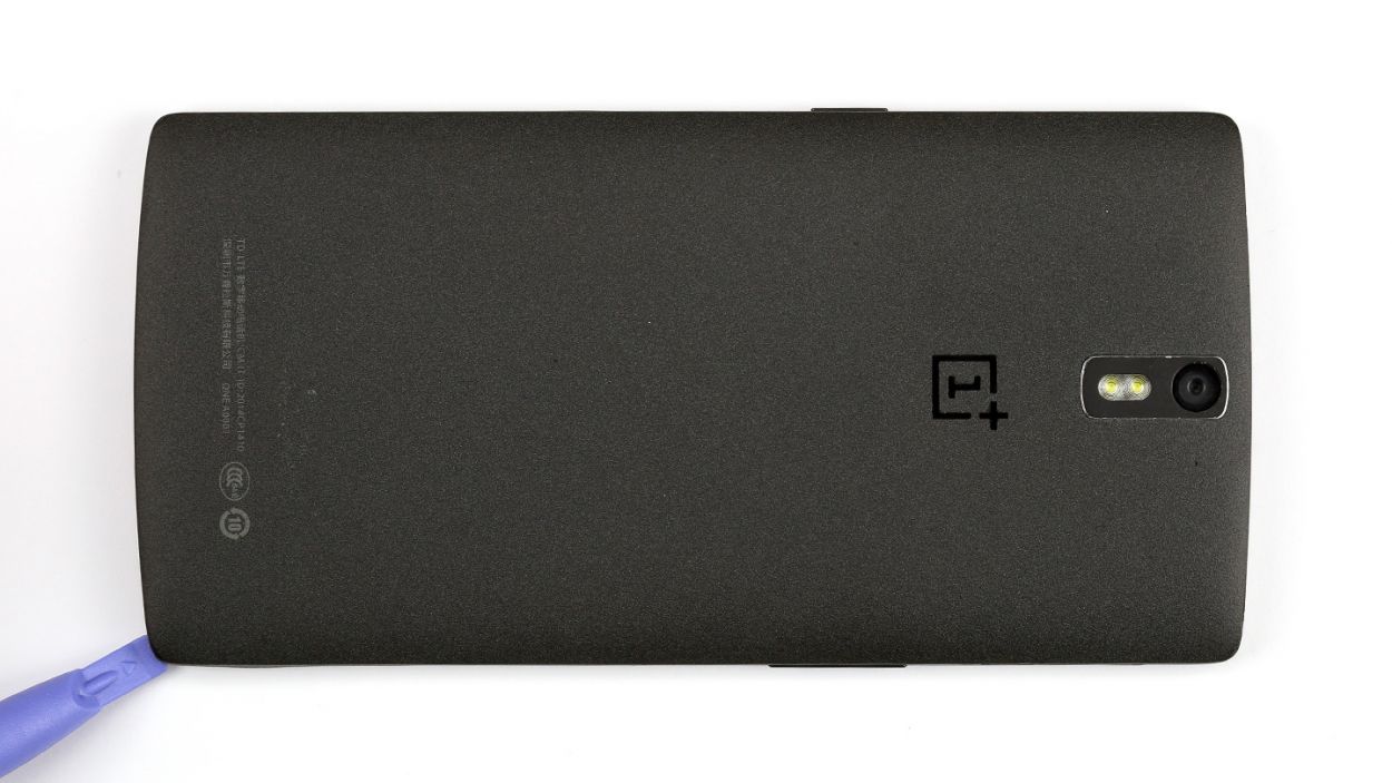
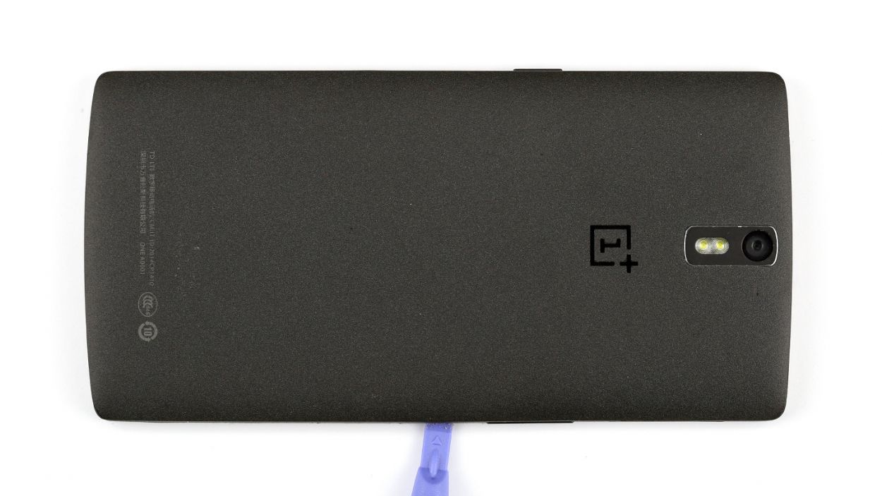
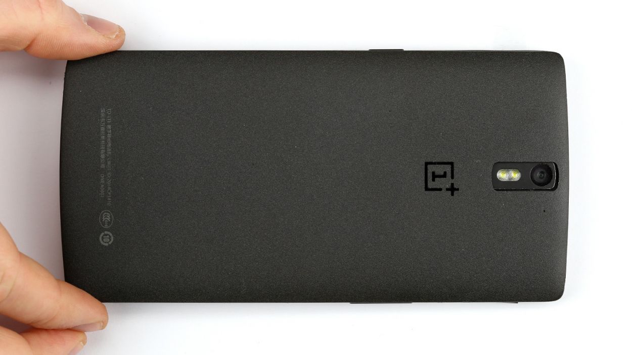
– Insert a thin, flat, tapered spudger into the gap at the corner of your smartphone. There are several clips on the outside under the back cover. You have to disconnect them by moving the spudger around the entire smartphone one time. Alternatively, you can detach the back cover using your fingernails.
– Then you can take off the back cover.
Step 3
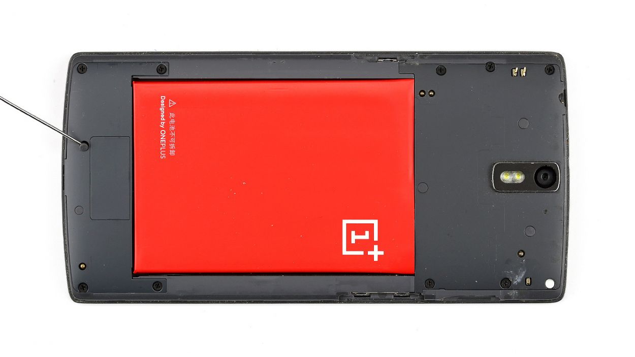
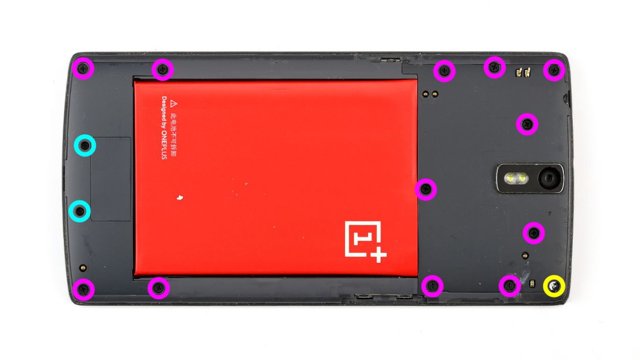
– Time to get those screws out! Start by removing all 15 Phillips screws that are keeping the plastic cover snug and secure.
– Keep an eye out for 5 sneaky Phillips screws hiding under a rubber cover. Grab a sharp object to gently lift that cover off and reveal the treasures beneath. We’re talking about 12 x 3.1 mm Phillips screws here!
– Now, let’s tackle the next batch of screws. You’ll need to remove 12 x 3.1 mm Phillips screws, 2 x 3.1 mm Phillips screws (the small ones), and 1 x 3.1 mm Phillips screw. You’ve got this!
– With those screws out of the way, it’s time to lift off the logic board cover. Carefully insert the pointed tip of your ESD spudger into the headphone jack and gently lift the black cover. Don’t forget to pry it out at other points too!
Step 4
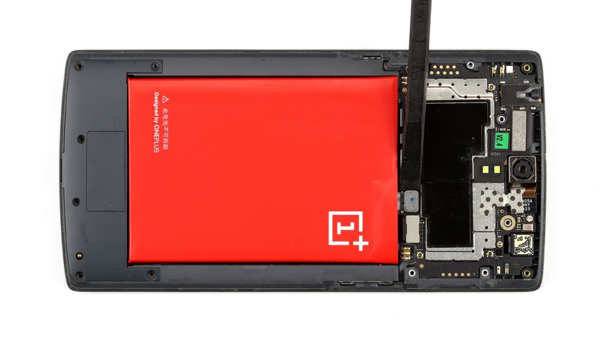
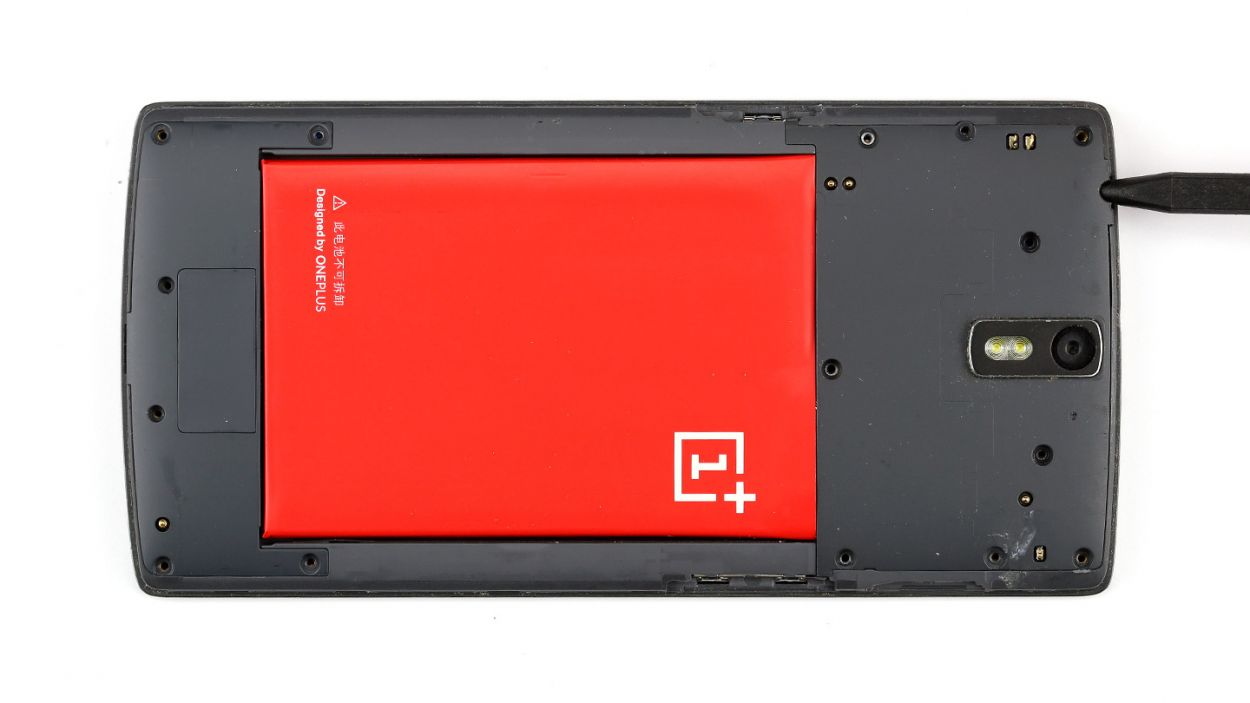
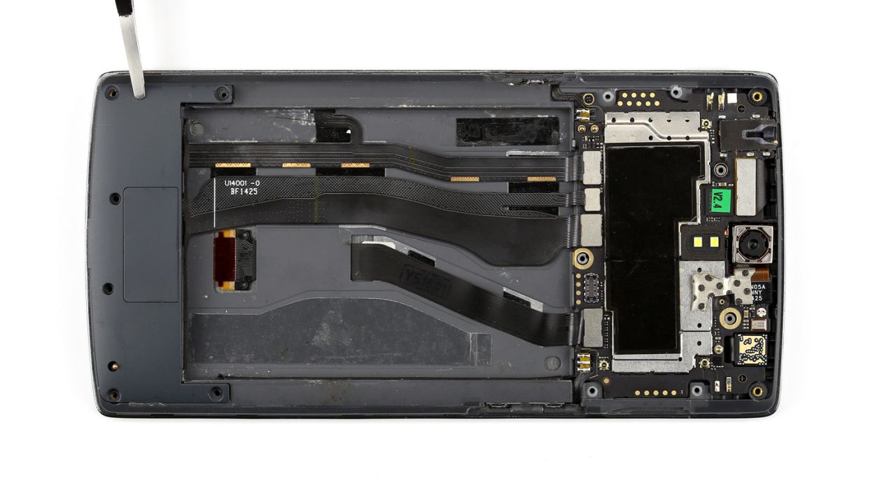
– Alright, let’s get that OnePlus One powered down! Press and hold the standby button for about three seconds, and just follow the on-screen instructions to turn it off.
– Next up, it’s time to gently detach the battery connector. Grab your spudger and place the pointed tip just below the contact—be super careful here! Lift it up slowly, and check out the pictures for the best spots to avoid any mishaps with those tiny resistors.
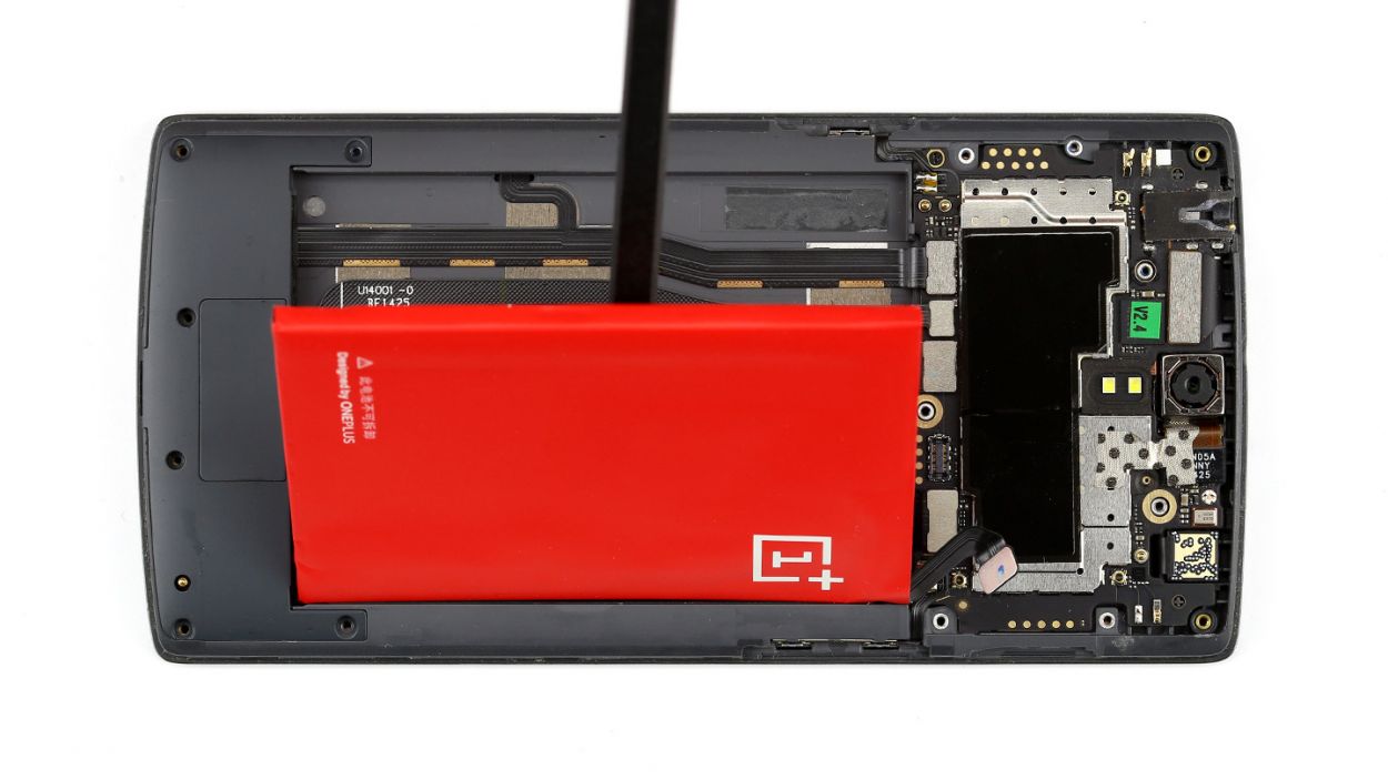
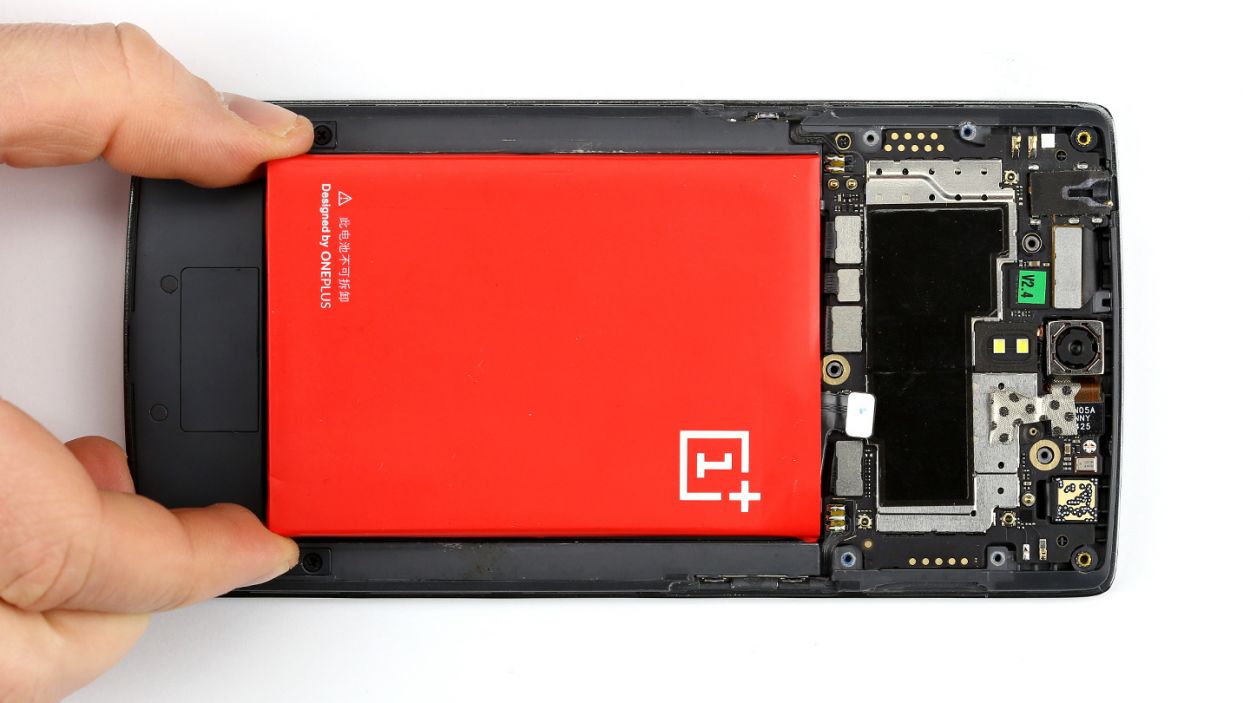
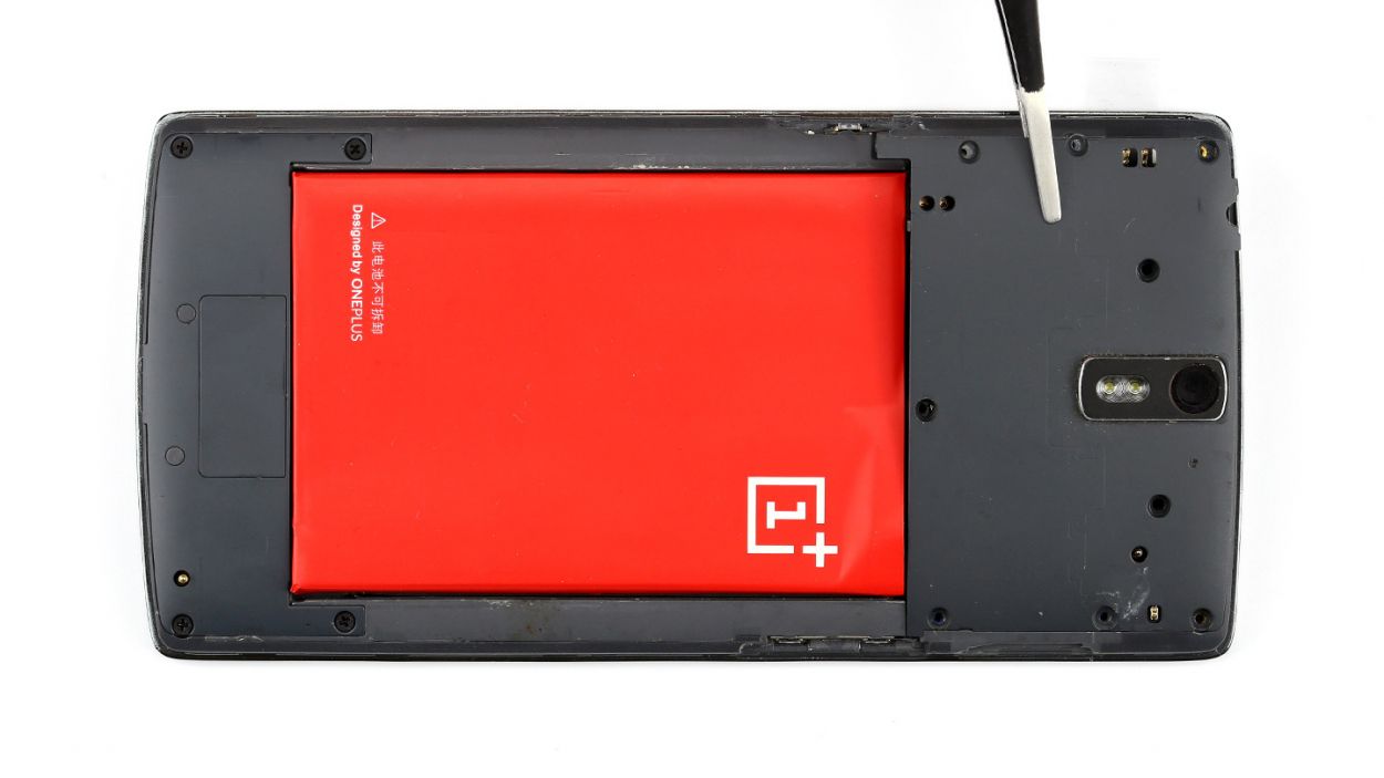
– Now, with a little finesse, use the spudger to lift the battery out and remove it. You’ve got this!
Step 5
– Grab that spudger and slide the flat end right under the cover near the charging port—be gentle, like you’re lifting a car off a kitten! Once you’re in there, give the cover a little nudge to lift it off. Your stereo speakers are waiting for you underneath.
– And just like that, you can pull them out!
Step 6
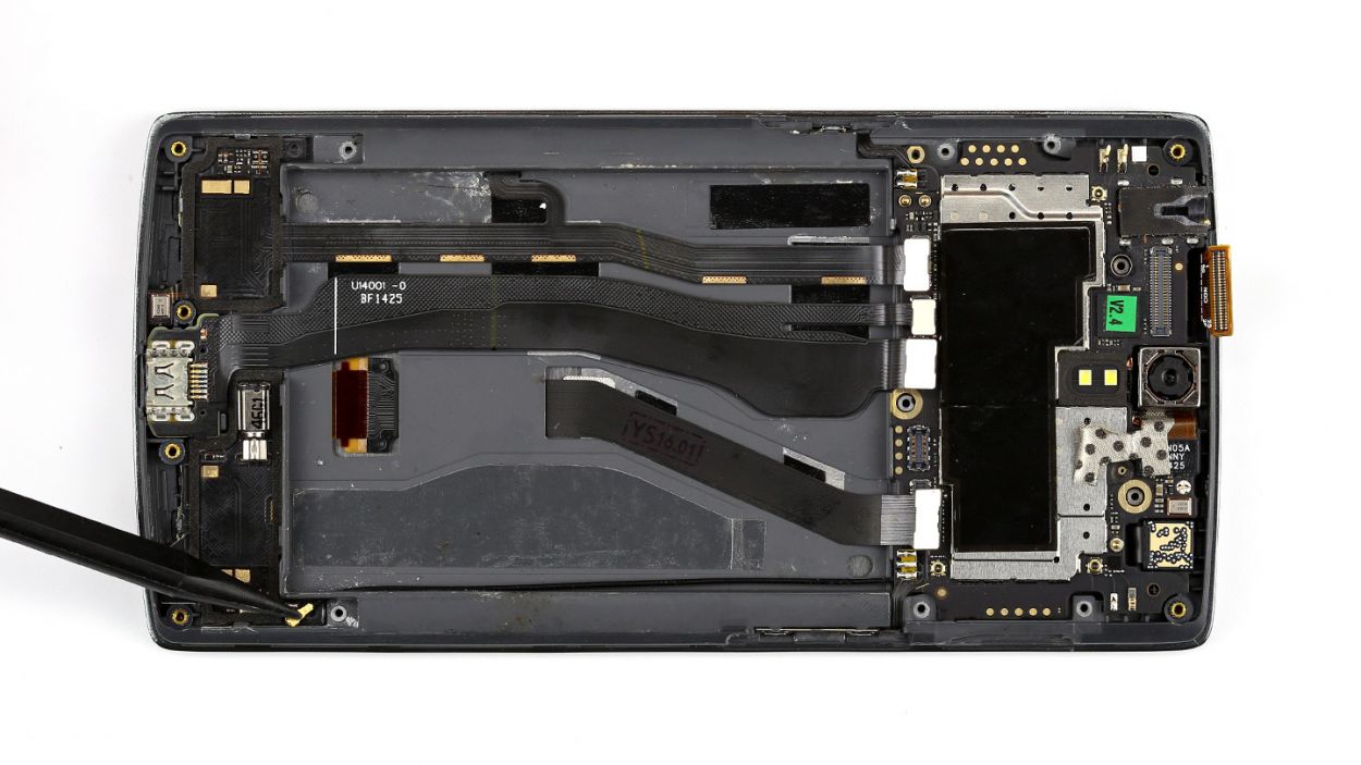
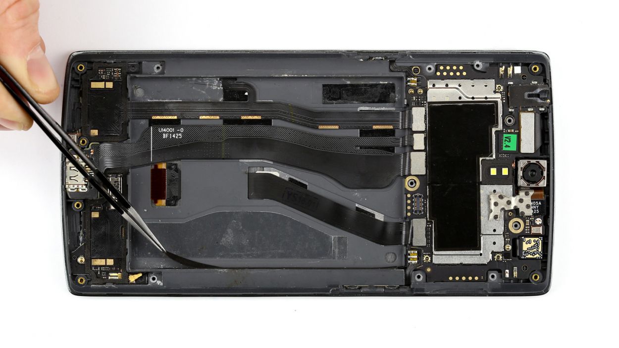
– ZFirst you have to remove the two black stickers on the side. You can easily pull them off with a pair of tweezers.
– Now you can disconnect the antenna cable from the connector using the pointed tip of the metal spatula, and then remove it.
Step 7
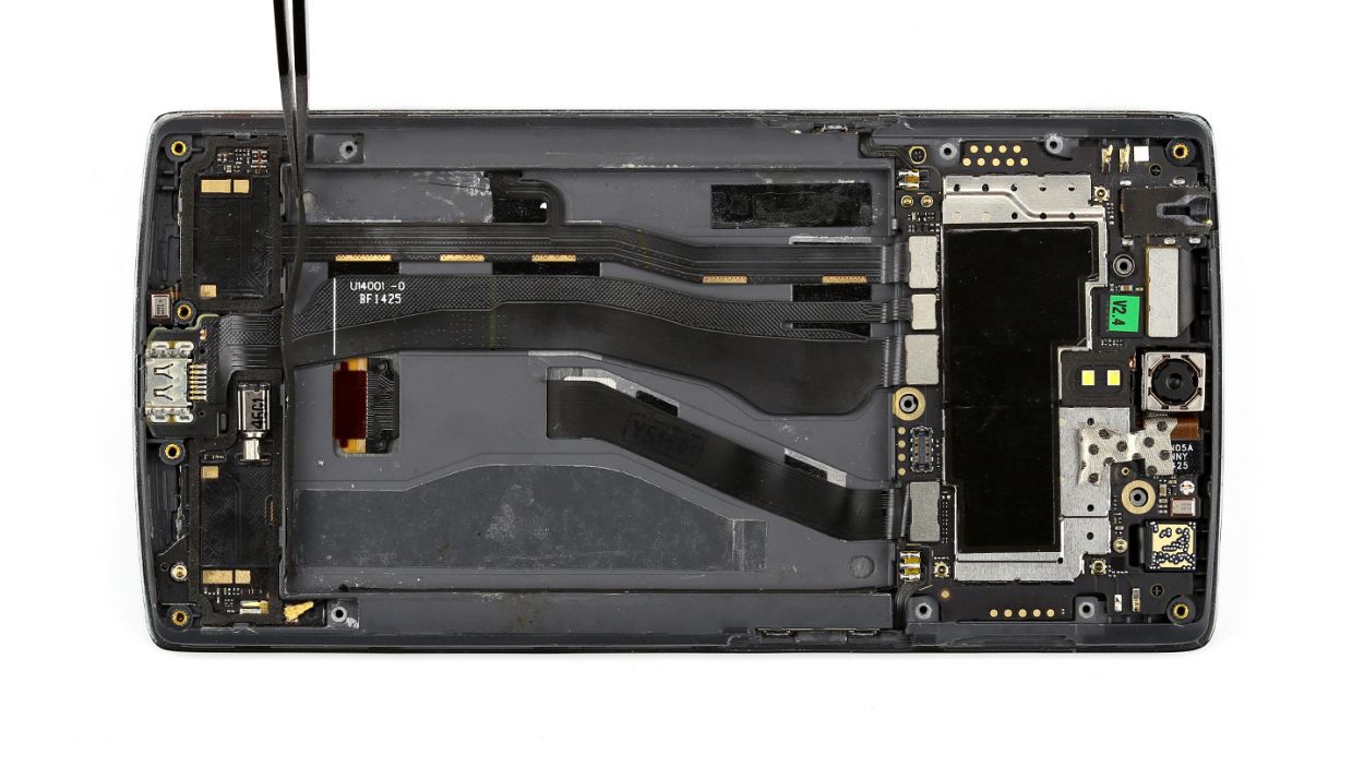
– The standby and volume buttons are connected to their own ribbon cables, which are securely soldered onto the logic board. No worries, you’ve got this!
– Grab your trusty metal spatula and gently pry off the cable, which is just a little bit glued to the frame. Easy peasy!
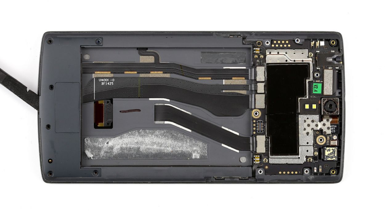
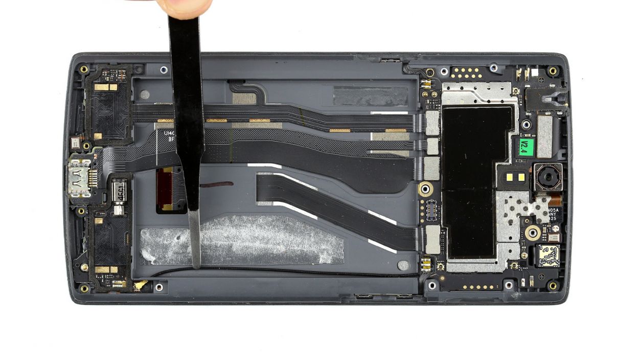
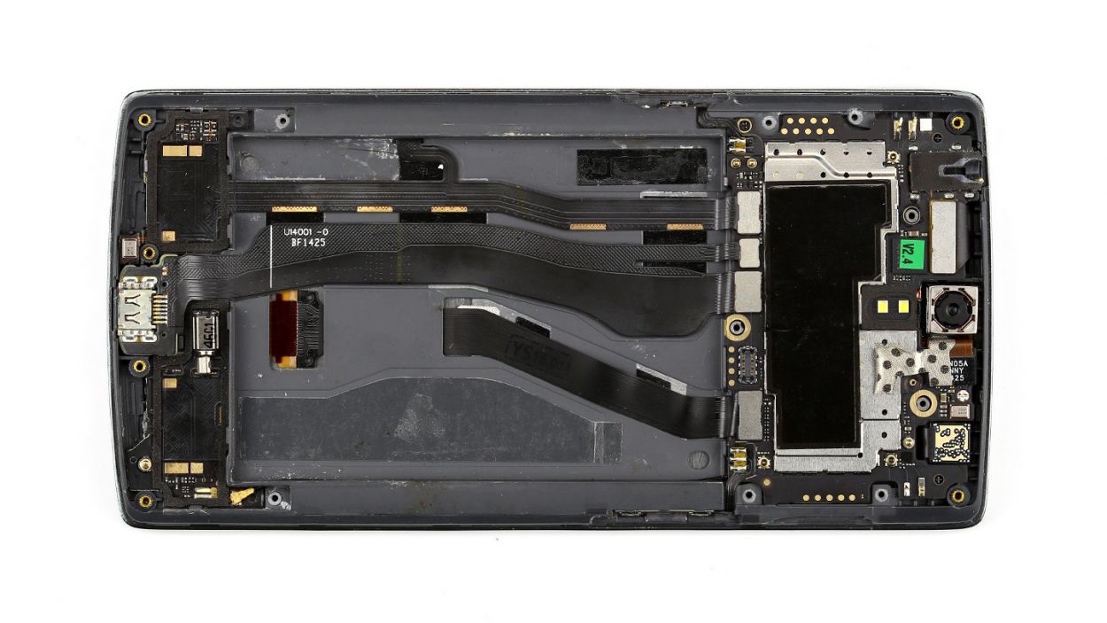
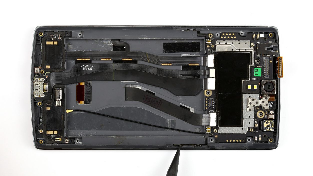
Step 8

Be super careful not to accidentally snap off those little resistors and coils that are snugly soldered onto the logic board. We want everything to stay in one piece!
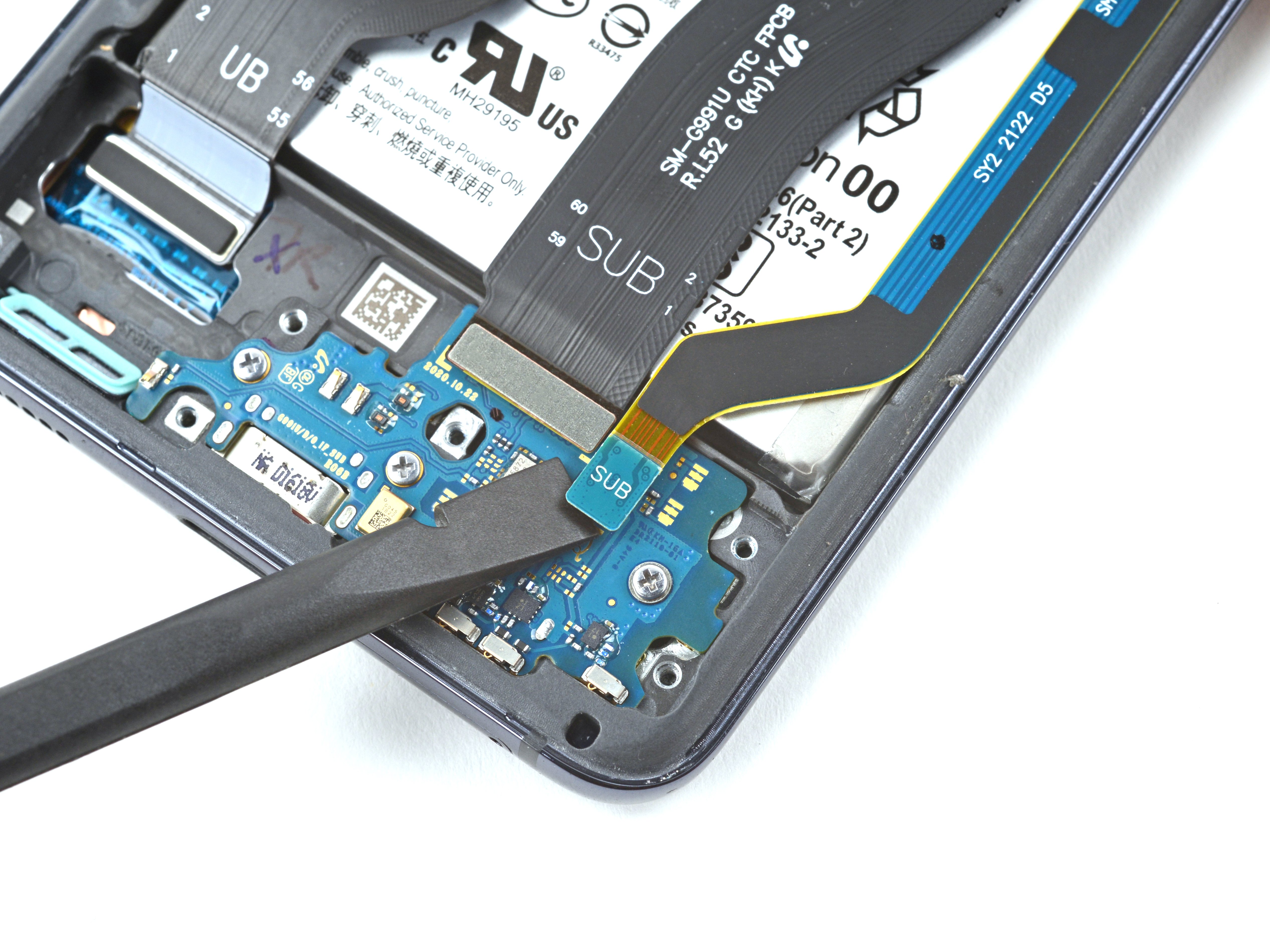
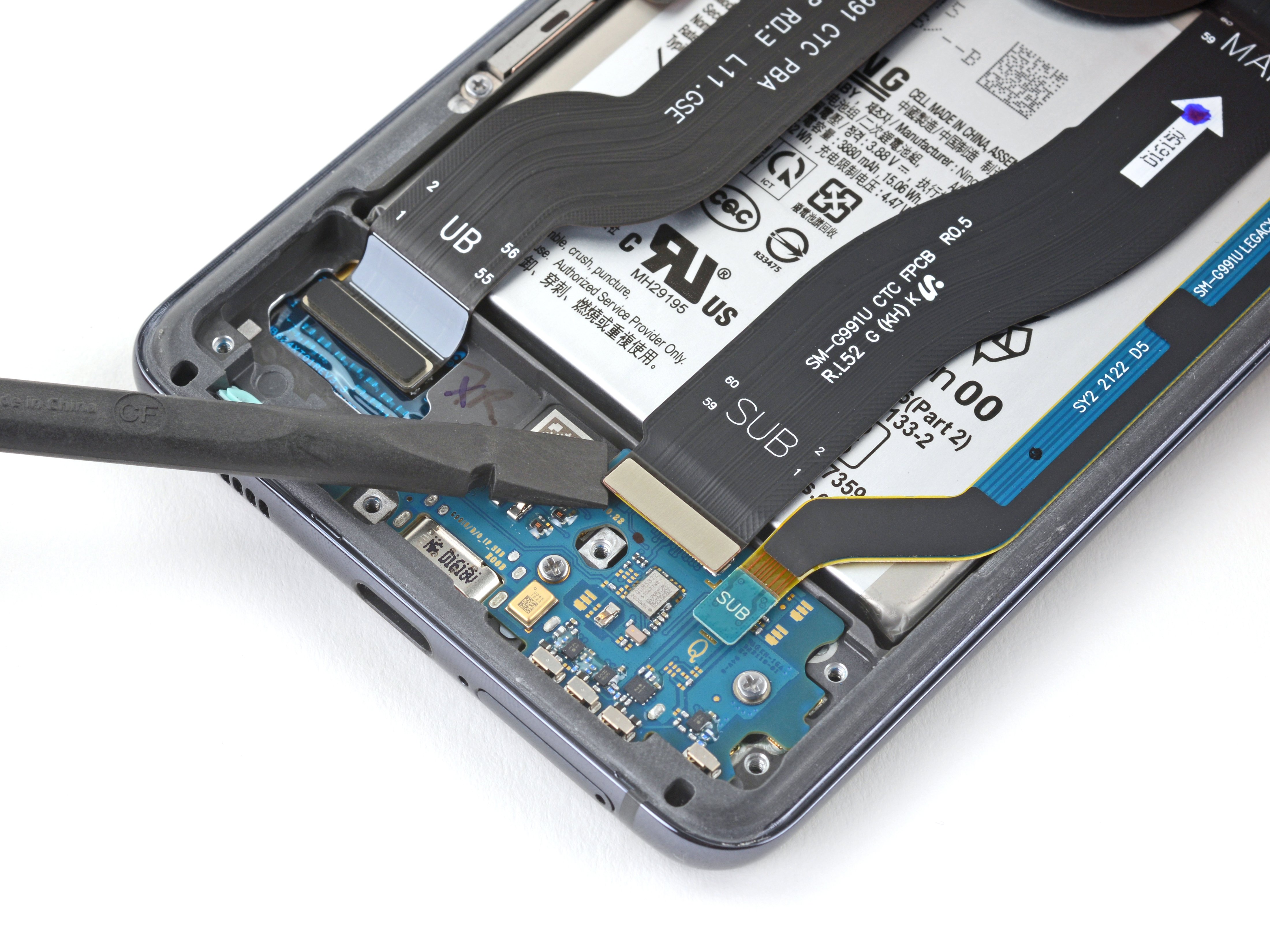
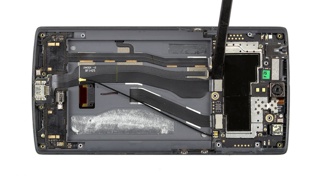
– Alright, it’s time to gently disconnect those five connectors. Take your time and be super careful!
– Grab your spudger and place the pointed tip or flat end just a smidge below the contact, then carefully lift it up. Remember, we want to keep those resistors and coils on the logic board safe and sound!
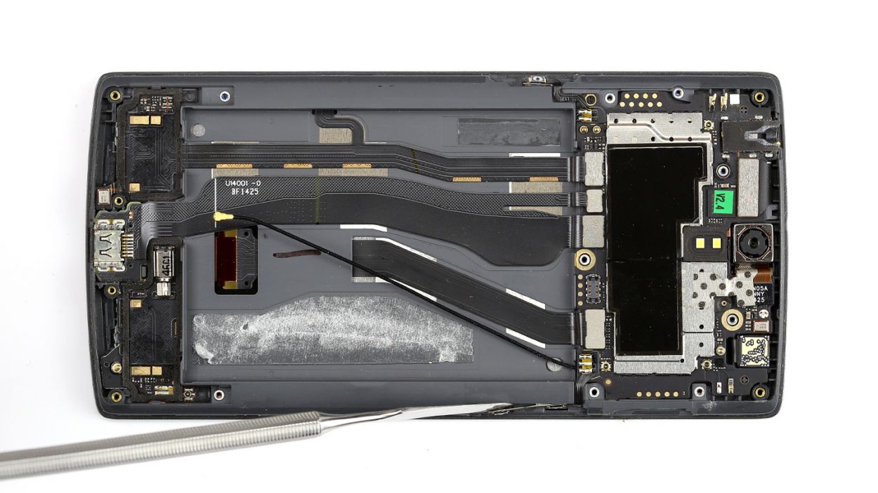
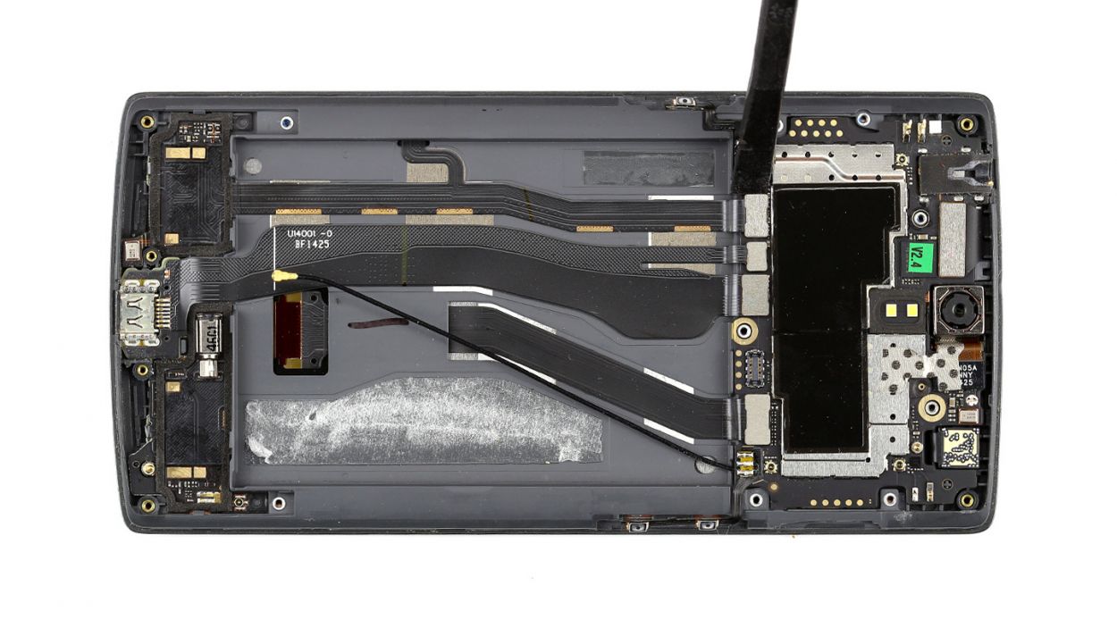
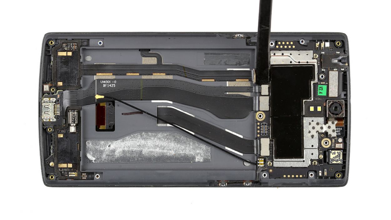
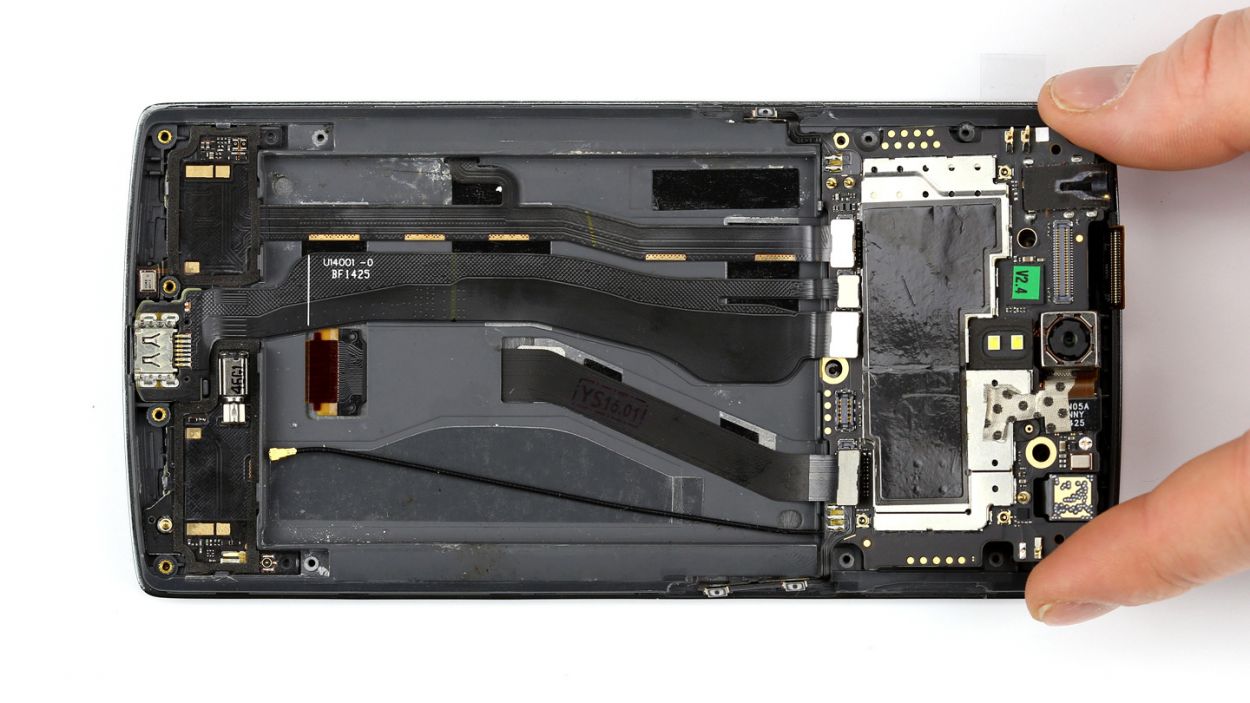
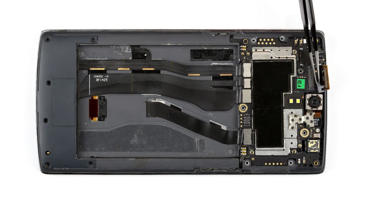
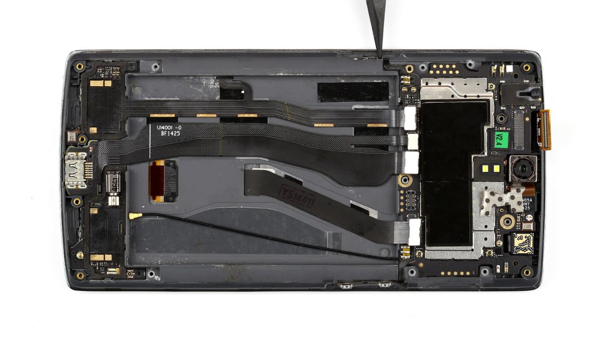
Step 9
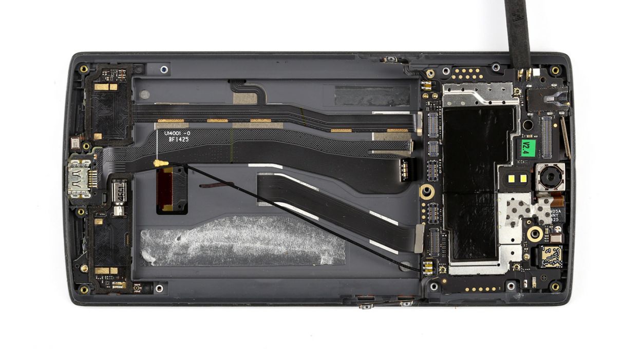
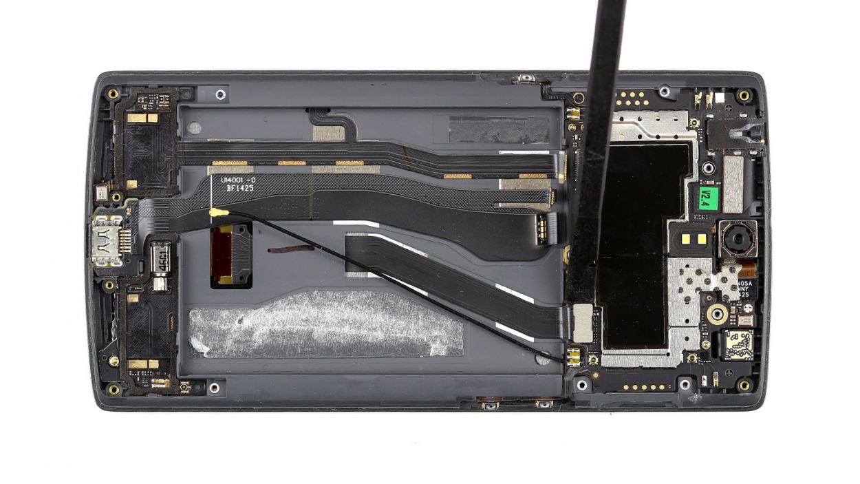
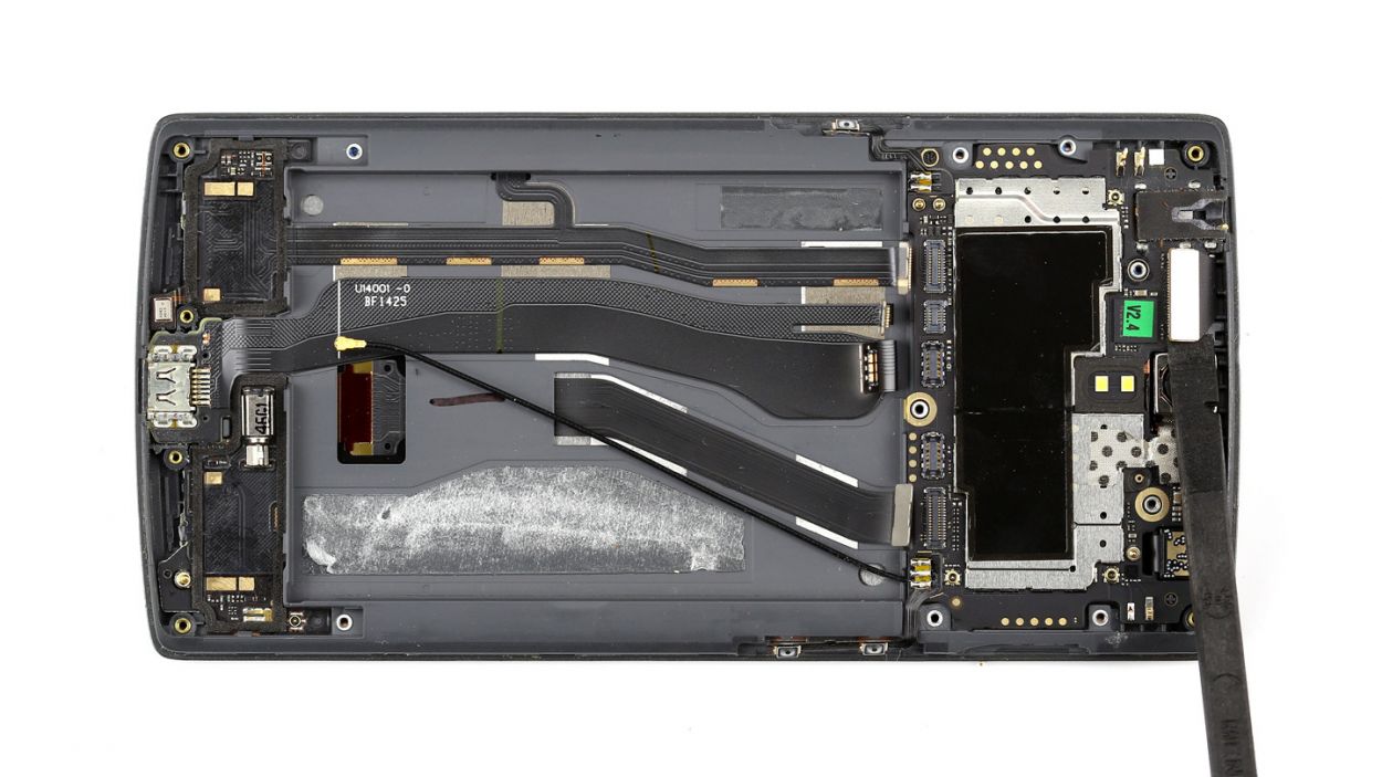
Alright, don’t forget to take out that tiny screw lurking near the camera connector. It’s hiding just below the camera, so give it a little love tap! Remember, if you need help, you can always schedule a repair.
– Now, gently lift the logic board with the spudger and remove it by hand. You’ve got this!
Step 10
– Time to say goodbye to the earpiece! Grab your trusty laboratory spatula or spudger and gently slide the pointed tip underneath the earpiece. It might be stuck on there pretty well, so don’t be shy! If it’s being stubborn, a little warmth from a heat gun can help loosen that glue up.
– Now, go ahead and lift it off!
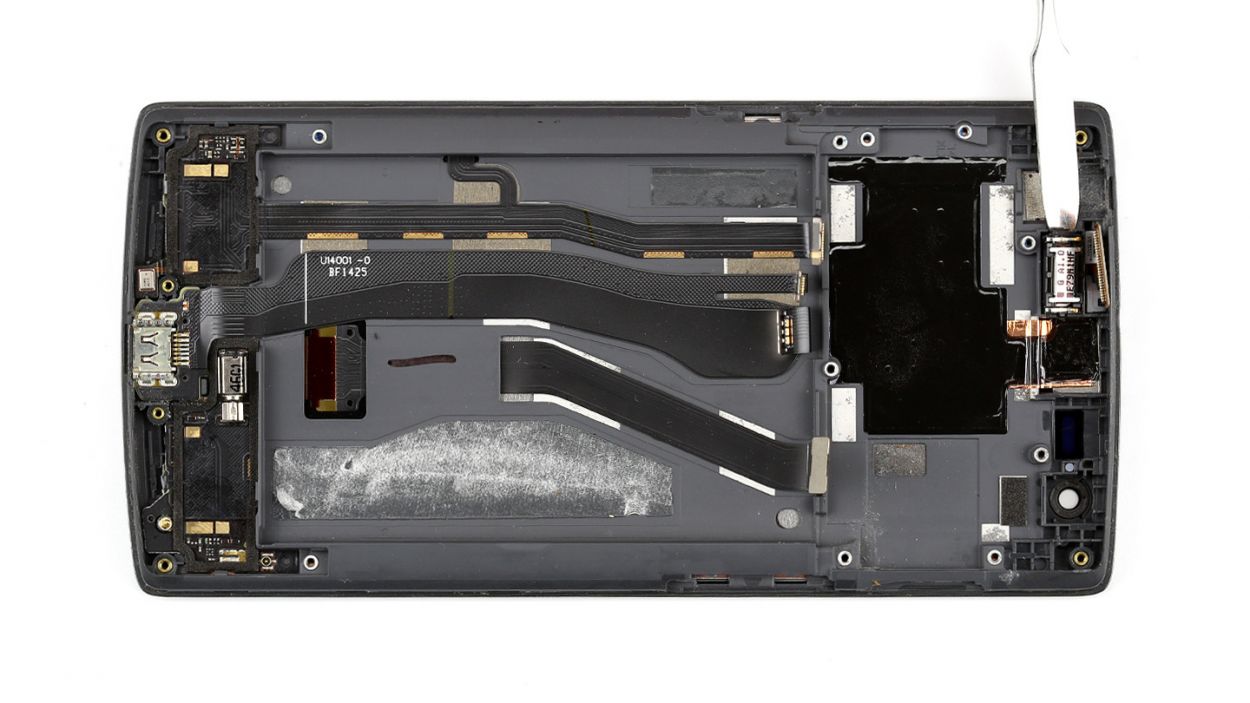
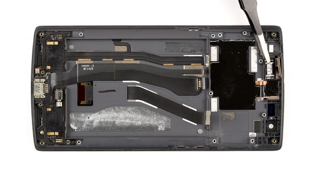
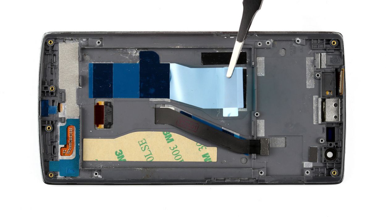
Step 11
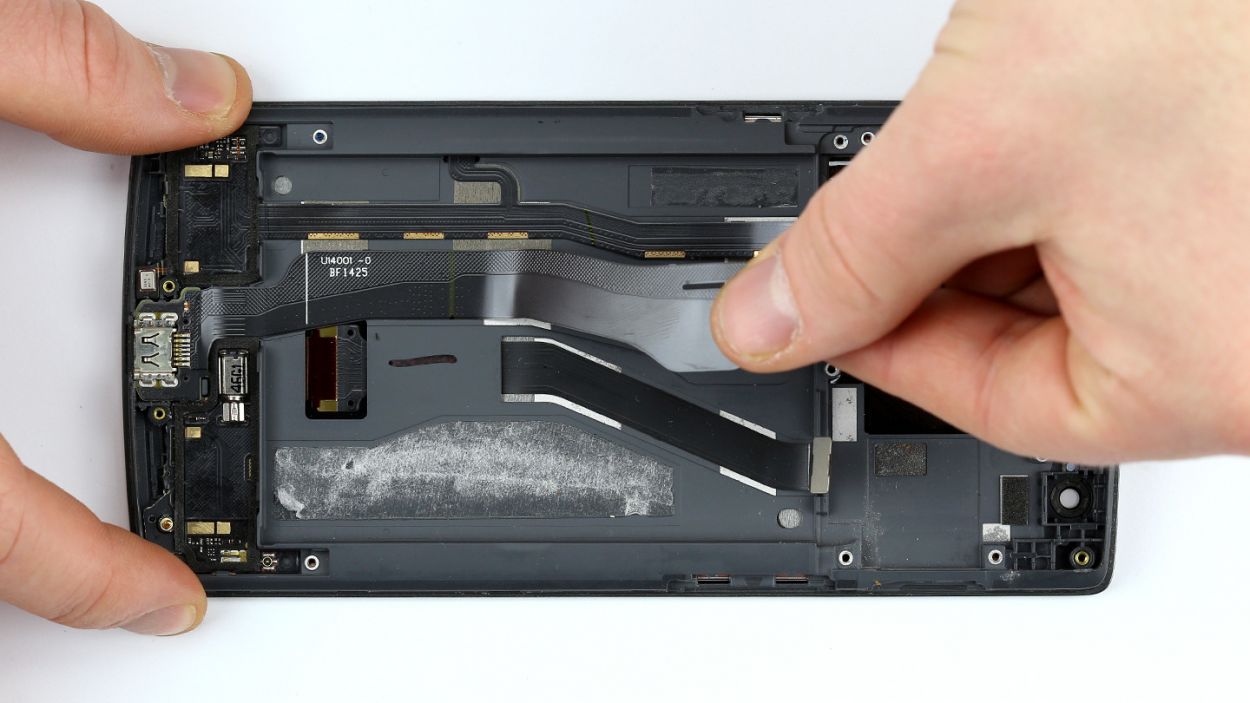
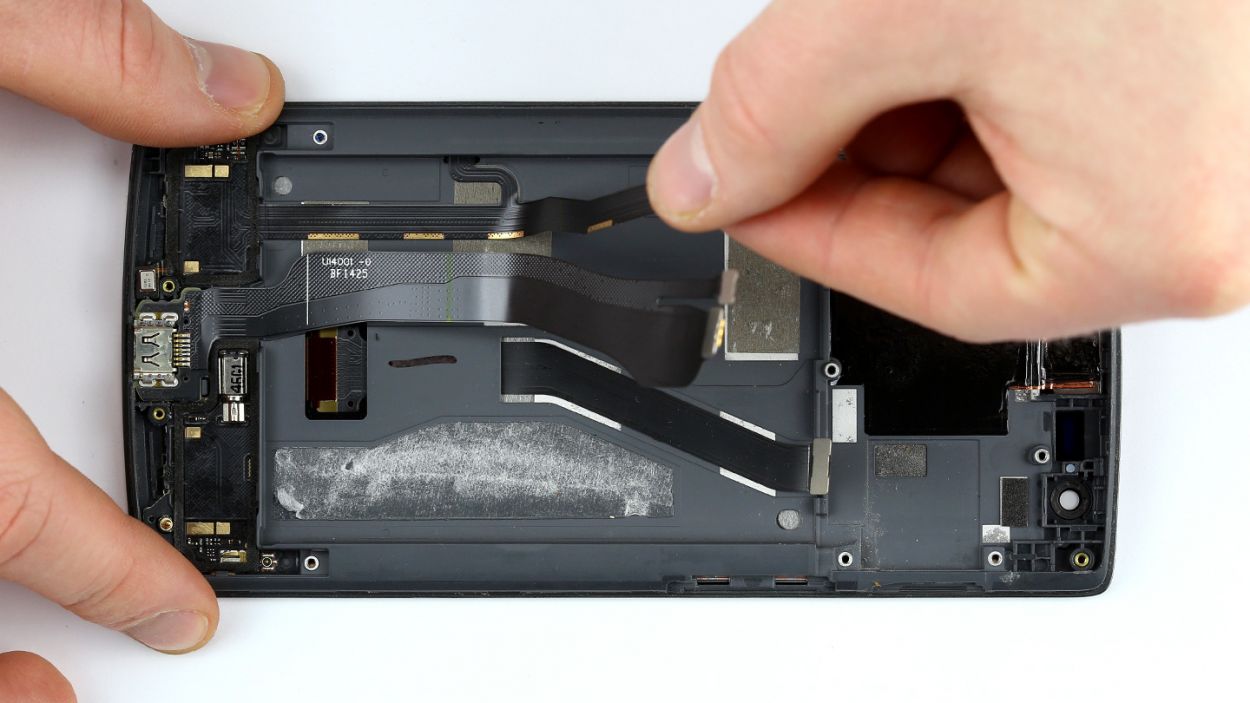
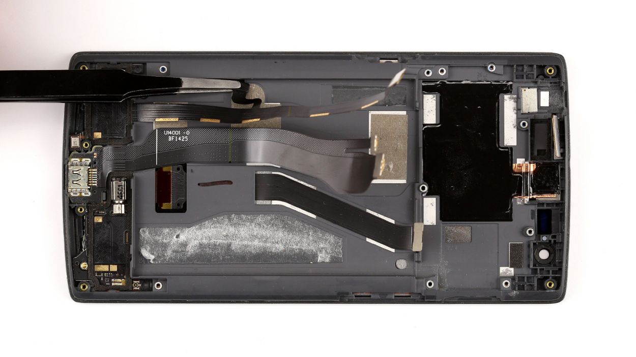
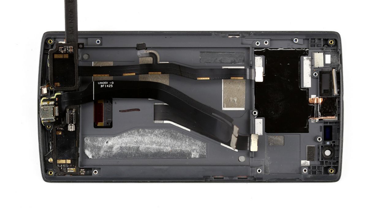

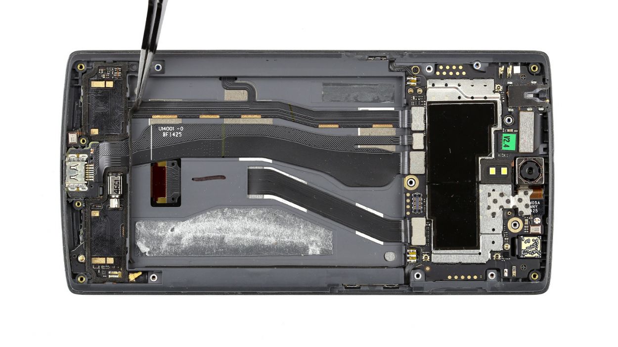
– Alright, let’s kick things off by gently removing those two ribbon cables that are snugly glued together. We’ve got this!
– To get started, let’s peel off the ribbon cable for the Micro-USB port. It’s just hanging out there, lightly glued to the frame. You could also remove it along with the port if that’s your style.
– Next up, it’s time to detach the ribbon cable for the stereo speakers, vibration motor, and antenna connector. Just a heads up, it has a little extension that goes into the frame, so make sure to separate that part too.
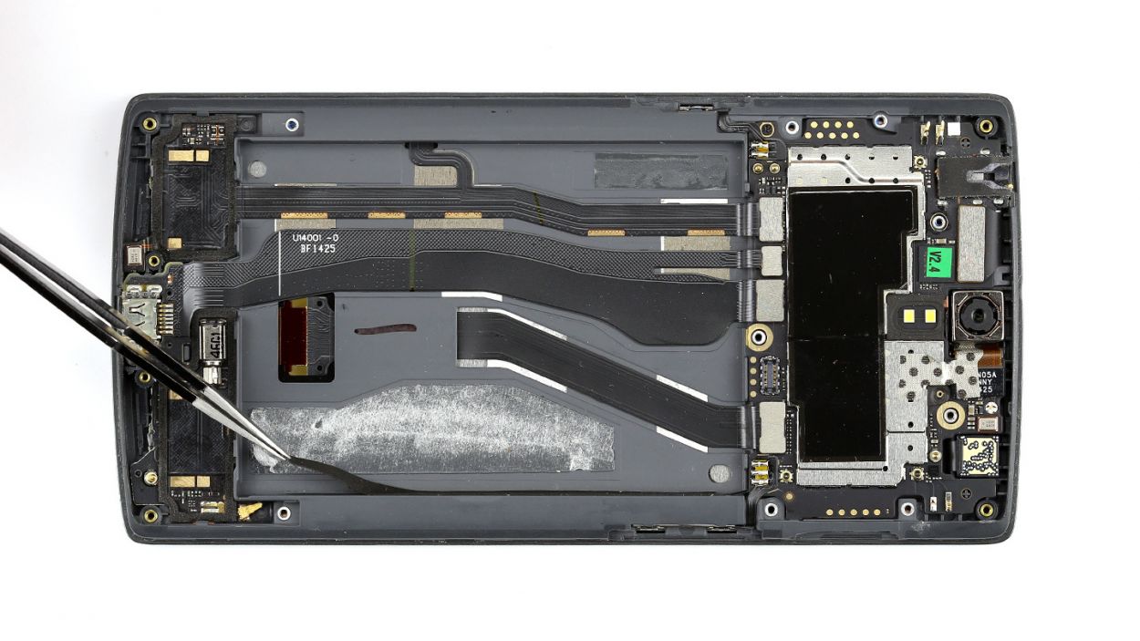
– For our second act, we’ve got another large ribbon cable glued to the bottom edge of the frame. Careful now! Slide the flat end of your spudger under the cable and detach it like a pro.
– And now, it’s time to remove it! You’re doing great!
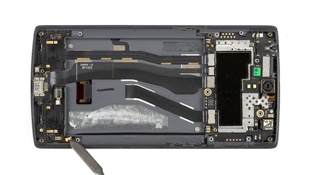
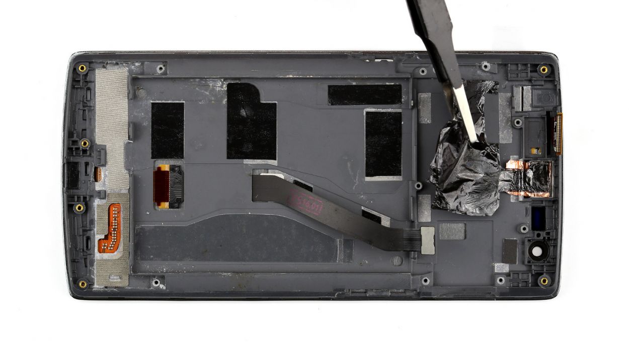
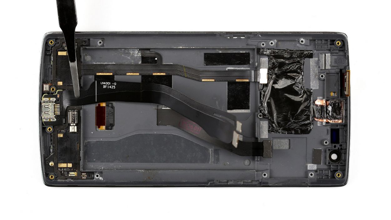
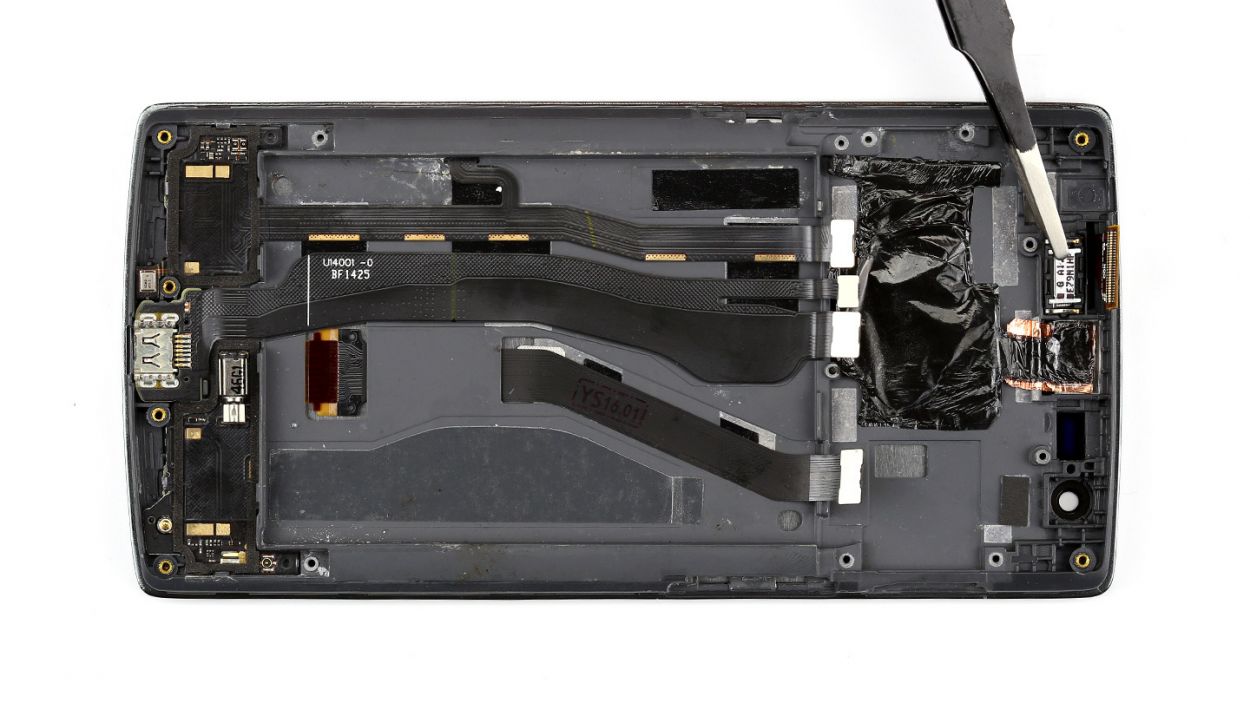
Step 12
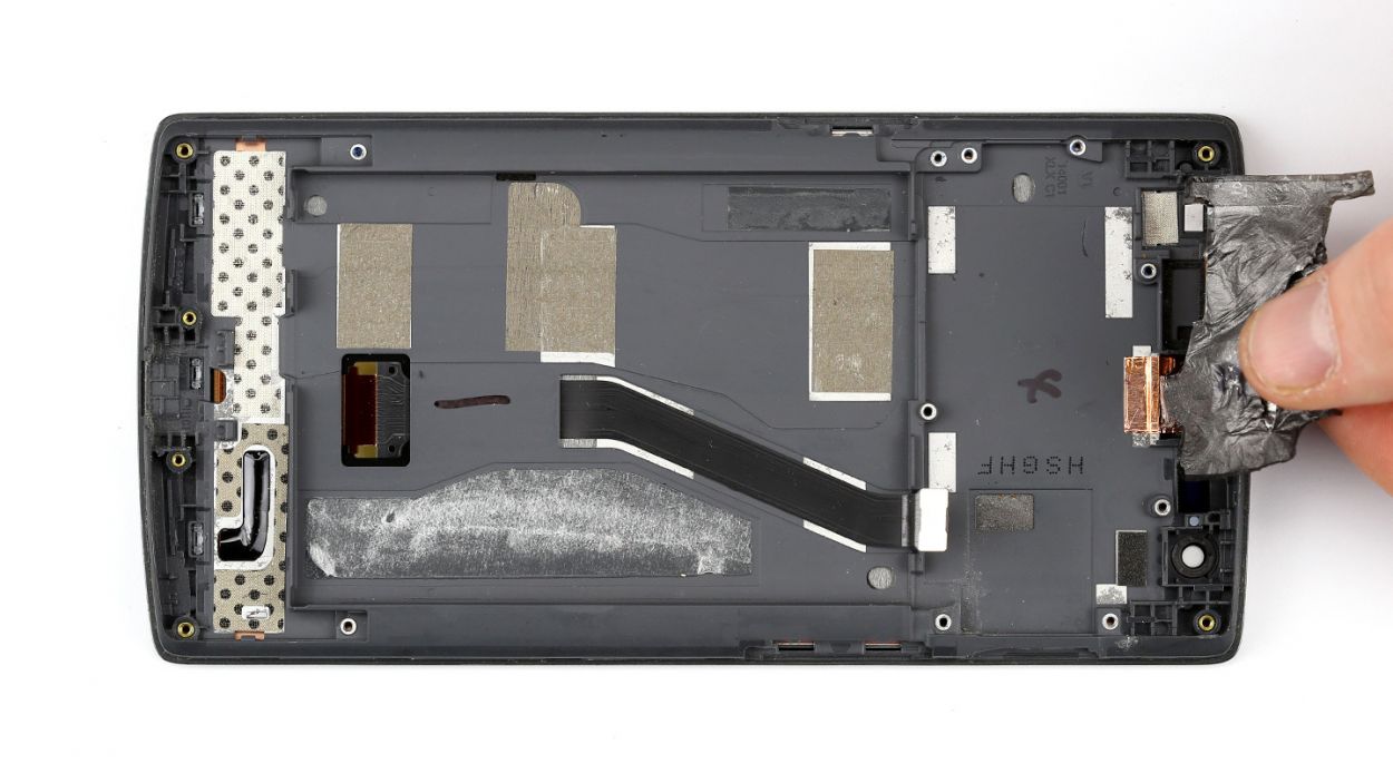
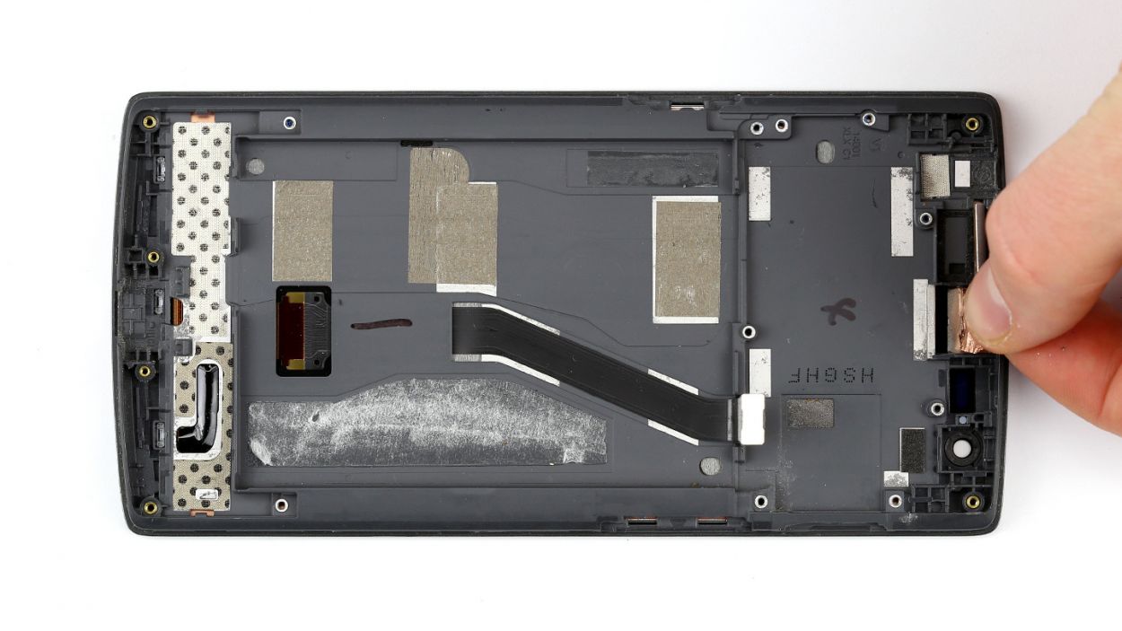
– You still have remove the heat shield and the copper pad.
Step 13
– Screen features vary, so you might need to move more parts than shown here before your new screen’s ready to shine!
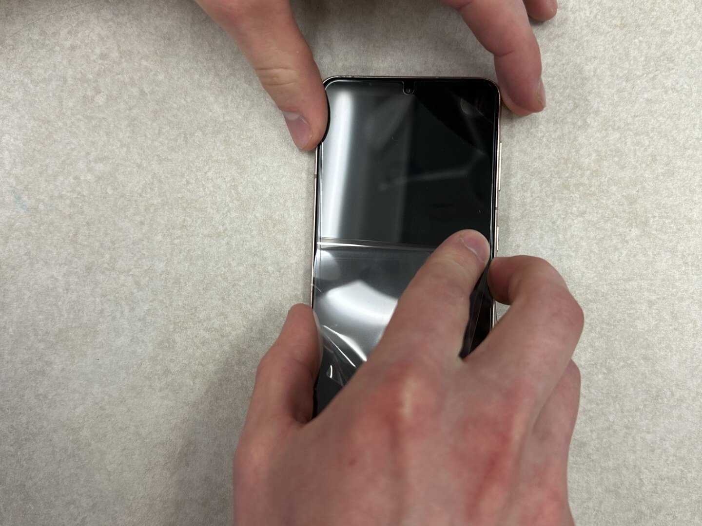
– Peel off that plastic film from the adhesive strips – or save it for later, no rush!
– Pop the heat shield and copper pad back where they belong. Easy peasy!
Step 14

– Let’s get those dock connector and speaker cables back in their rightful spots! It’s an easy task.
– Just lay the dock connector cable over the speaker cable where the old glue has been holding it snugly in place.
Step 15
– Now put the earpiece back in the appropriate position.
Step 16
– Alright, let’s slide that logic board back into its cozy frame!
– Just a friendly reminder: keep those cables from sneaking under the logic board.
– Check out the picture to make sure your logic board is sitting pretty in the right spot.
– Pop in that little placeholder on the display connector like a pro.
– Now, it’s time to reconnect all those connectors to the logic board. You’ve got this!
Step 17
– Install the standby button and the volume buttons again. Use the spatula to press them into the appropriate positions.
Step 18
– Gently guide that antenna cable back through the tiny opening and make sure to connect it snugly to the logic board.
– Next up, let’s get those adhesive strips back in place.
Step 19
– Next up, let’s pop that cover back on along with the snazzy stereo speakers and fit them into their rightful spots. You’ve got this!
Step 21


– Now put the cover back on.
– Then fasten all the Phillips screws again.12 x 3.1 mm Phillips screws2 x 3.1 mm Phillips screws (small)1 x 3.1 mm Phillips screw
– Don’t forget to put the little rubber plugs back in.
Step 22

– It’s very easy to put the back cover back on. Put it on in the correct position and press it on all the way around the phone until it’s completely clicked into place.