DIY Guide to Replace HUAWEI P9 Standby Volume Control Cable
Duration: 15 min.
Steps: 11 Steps
In this guide, we’re here to help you swap out your P9’s finicky standby/volume control cable all by yourself! This repair is essential if your volume rocker switch has lost its groove or just won’t press down properly. Plus, if your device won’t power on, it’s time to tackle this part replacement. Let’s get started and bring the sound back to life!
Step 1
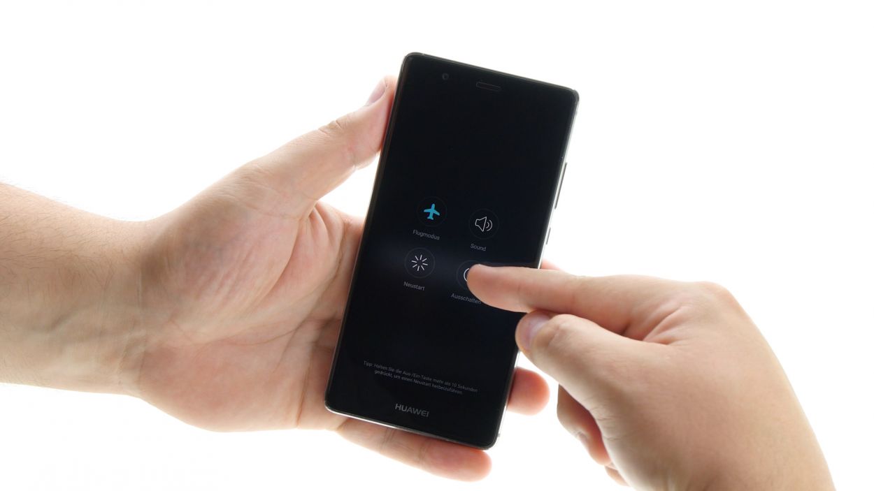
– Time to power down your device! Go ahead and press and hold that power button until the menu pops up. When you see the ‘Power off’ option, give it a tap, and just to be sure, tap it again to confirm. Easy peasy!
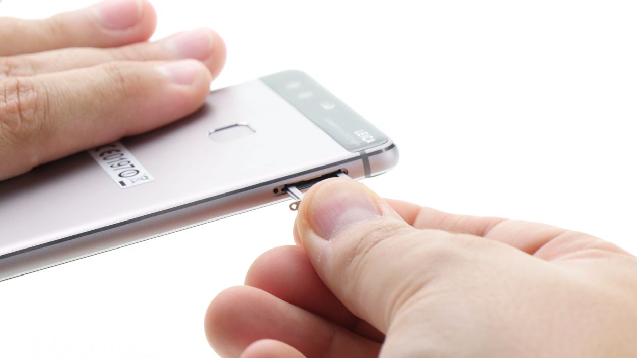
Step 2
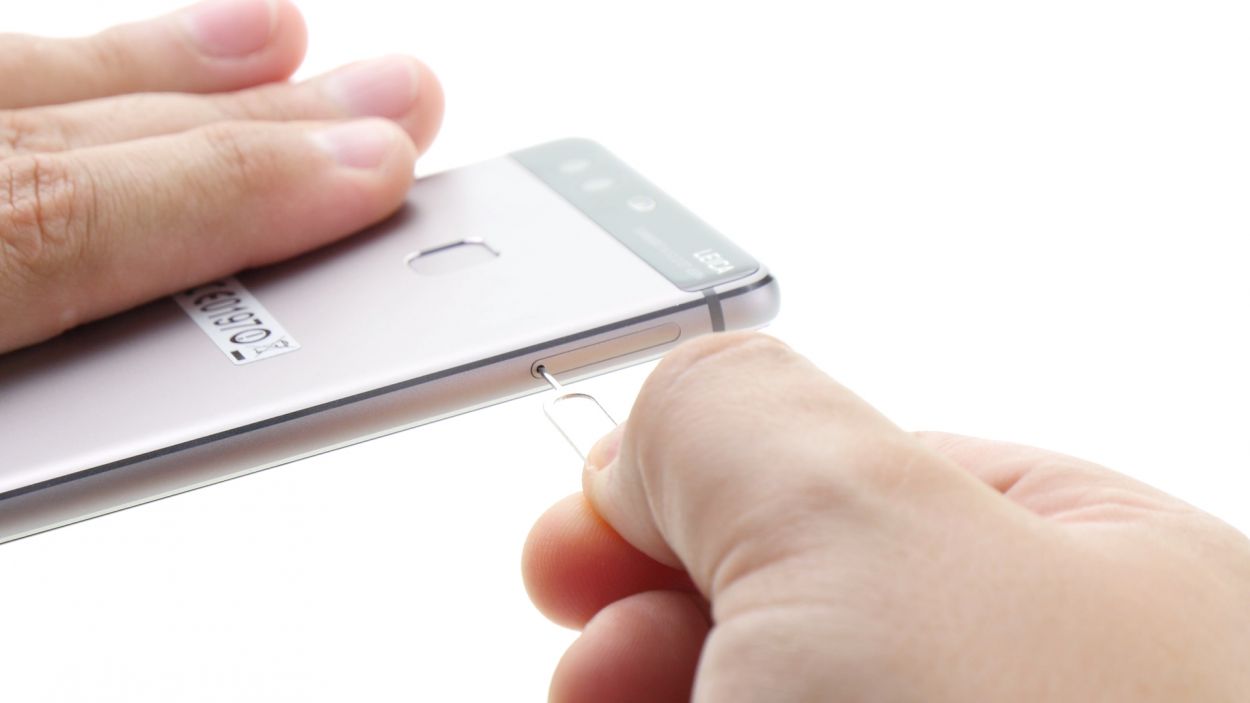
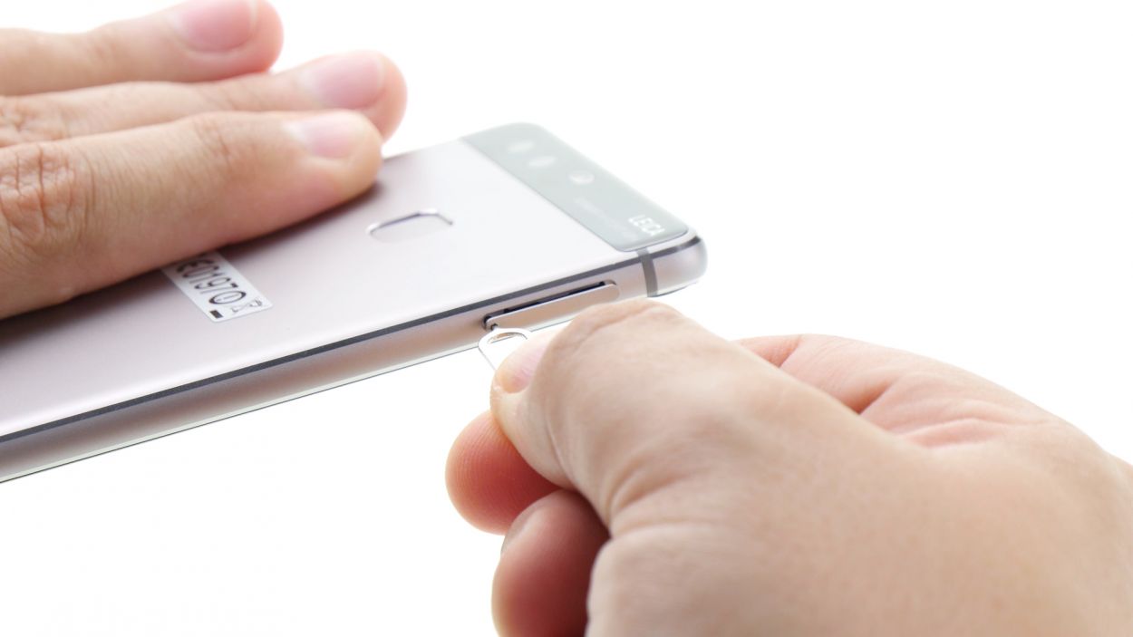
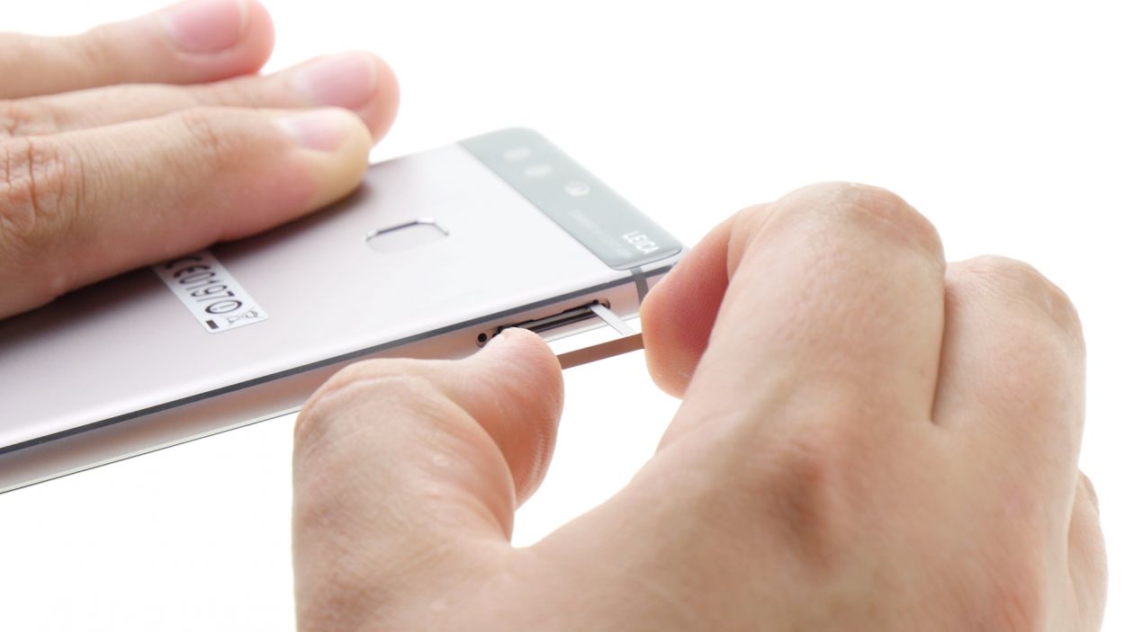
– Pop your SIM tool into the tiny hole on the tray to give it a little nudge and unlock it.
– Gently pull out the SIM tray and, if you’ve got them, take out the SIM and microSD cards too.
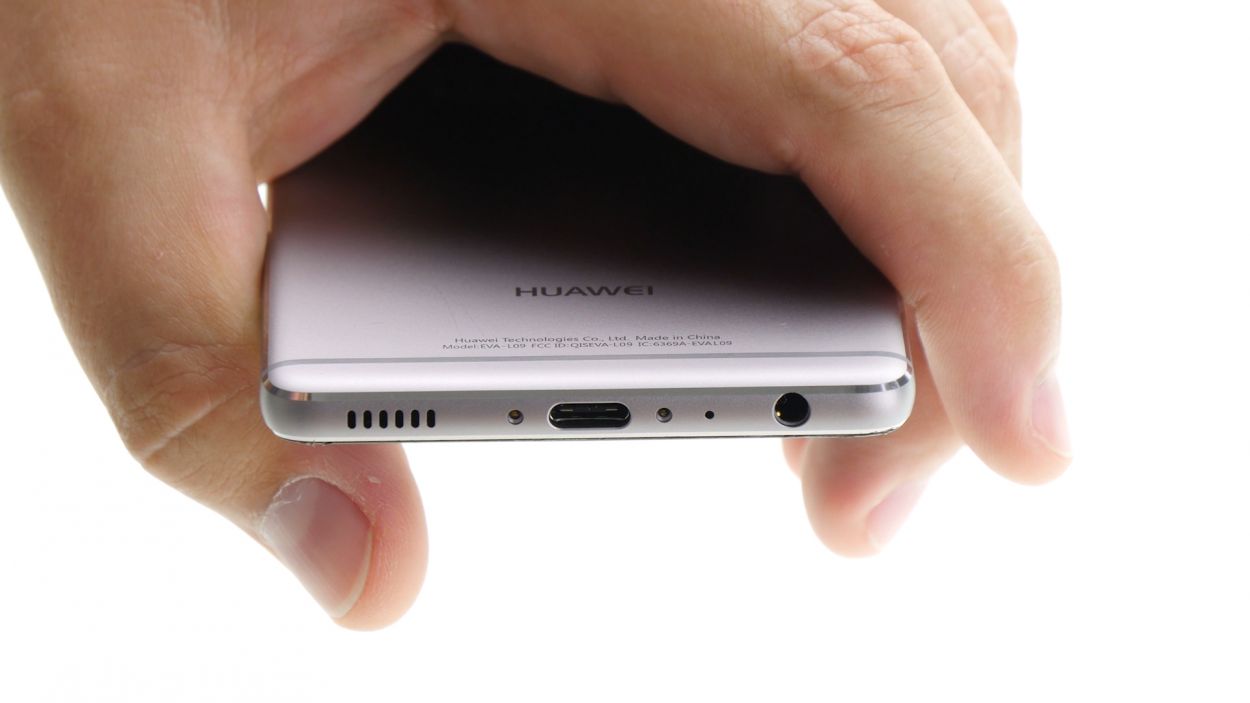
Step 3
2 × 2,8 mm P1 Pentalob-Schrauben
– Pop off those two screws hanging out at the bottom of your device! They’re the ones keeping the enclosure snug as a bug. Time to set them free!
Step 4
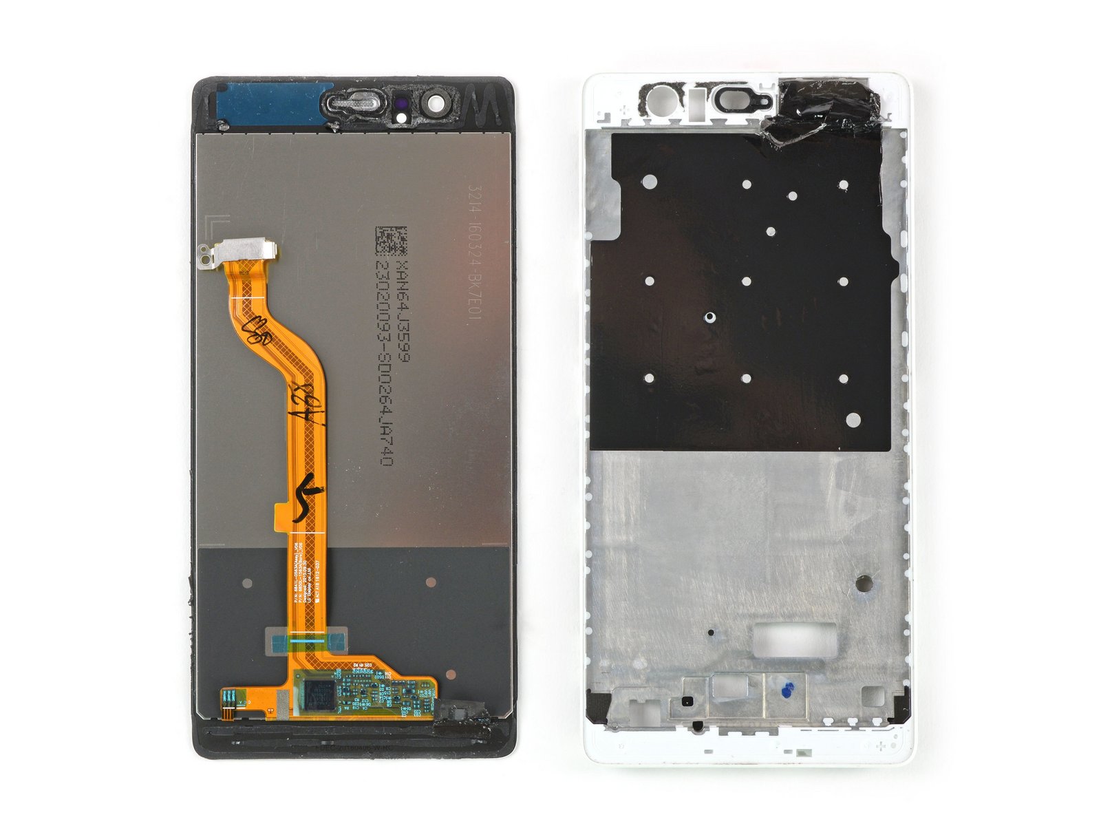
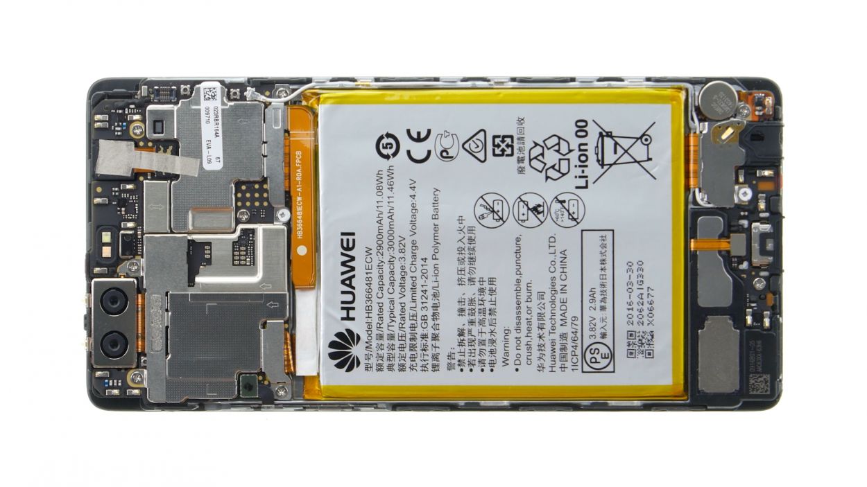
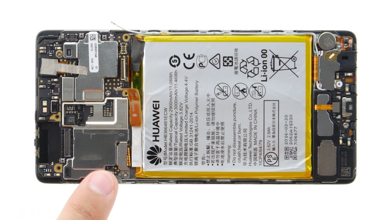
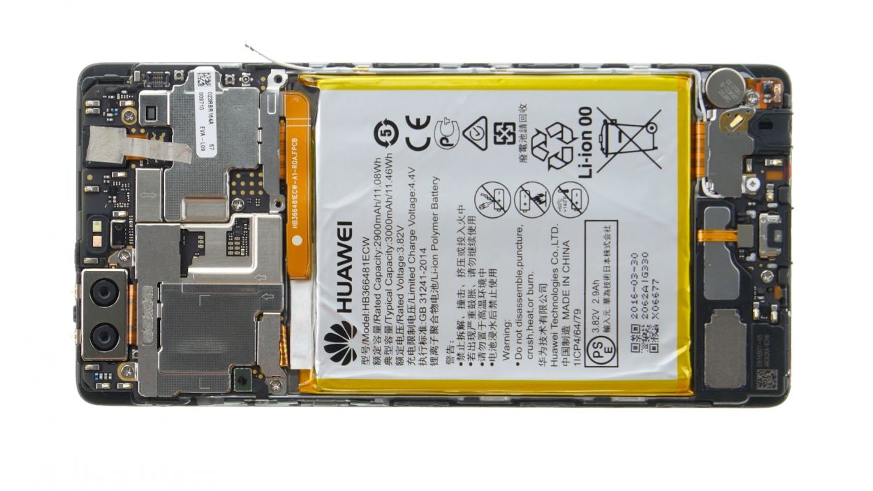
The fingerprint sensor is snugly tucked away in the back cover, connected to the motherboard by a flexible flat cable. When you’re removing the display, just keep an eye out for that cable and the board—let’s keep them safe and sound!
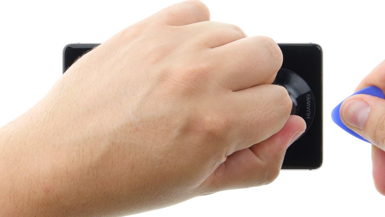
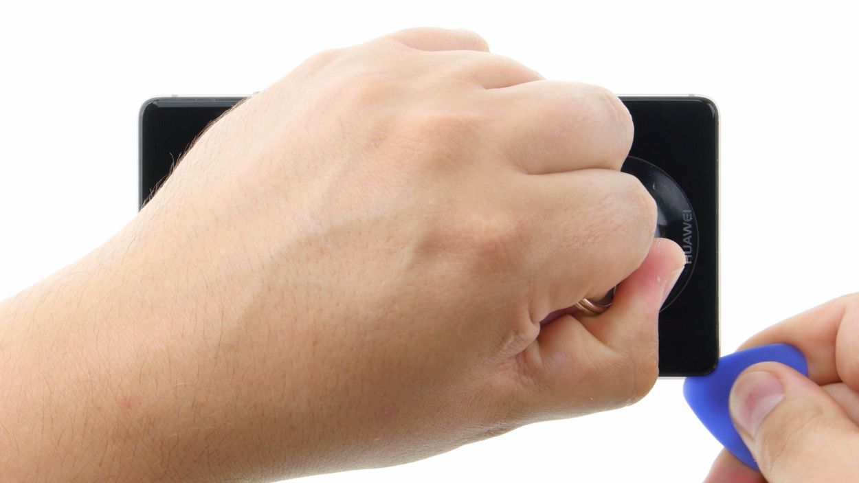
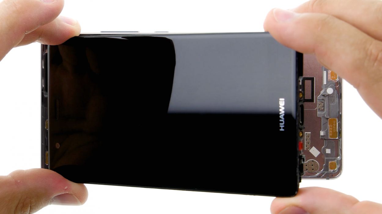
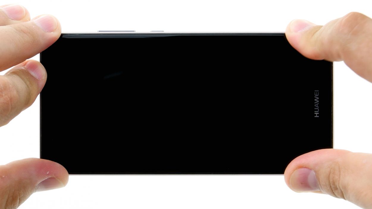
– Start by placing the suction cup nice and low on the display, right where it says ‘Huawei’. If the glass is so cracked that the suction cup can’t seal, a little tape on the display can do wonders.
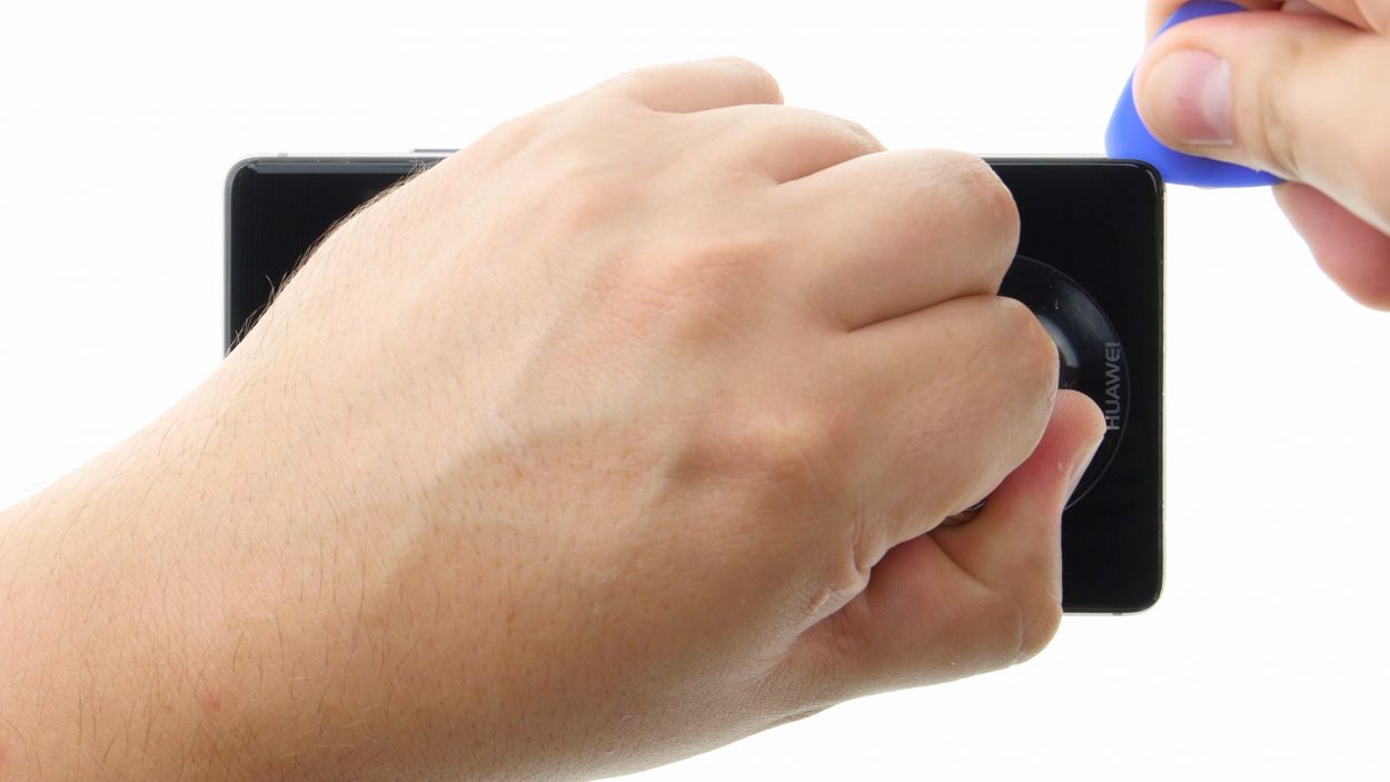
– Gently pull on the suction cup while you use the pick to nudge the back cover against the table. As soon as you spot a gap between the display and the enclosure, slide in that pick with care.
– Now, let’s work that pick along the edges to detach the display from the sides. Keep that suction cup gently pulling to help things along.
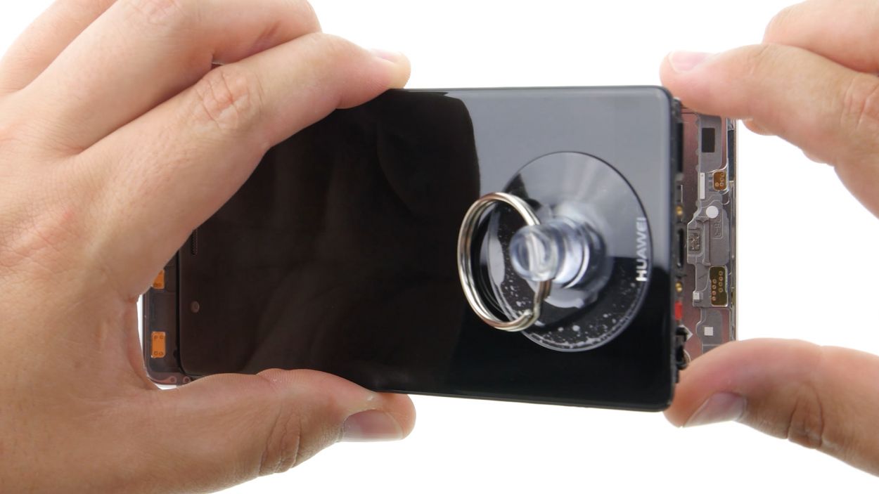
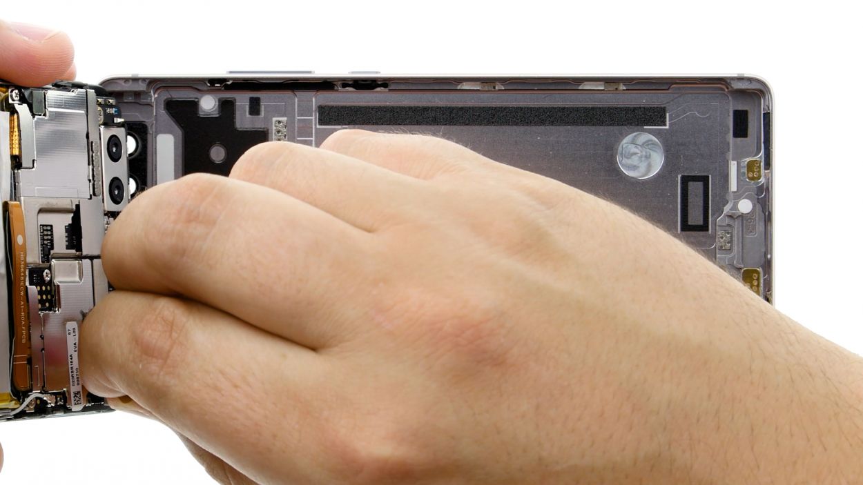
– Carefully lift the display up. Open the device at the upper edge like you’re cracking open a book. You should now be greeted by the connection cable.
– To disconnect the cable from the motherboard, just slide the spudger underneath the contact and gently pop it off.
Step 5

2 × 2,5 mm PH00 Phillips-Schraube
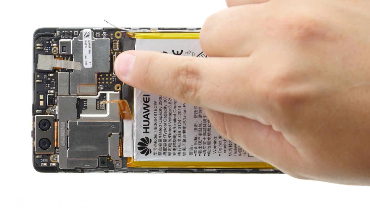
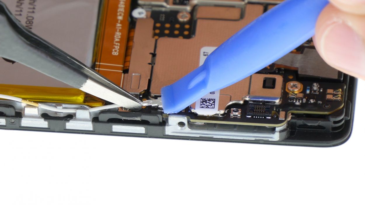
Antenna Cable
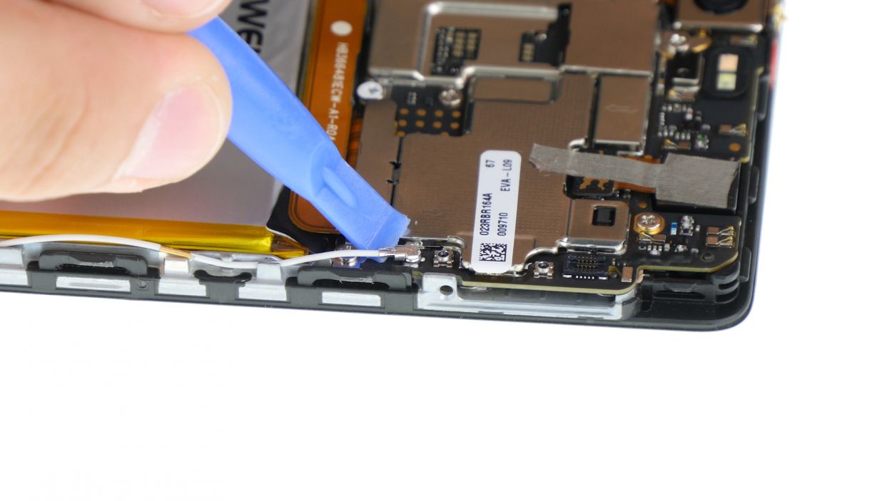
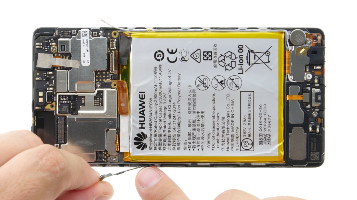
– Kick things off by disconnecting that white antenna cable from the motherboard. There’s a sneaky little screw hiding underneath it, waiting to be discovered!
– Next up, let’s get rid of the two screws that are keeping the plate stuck. They won’t know what hit them!
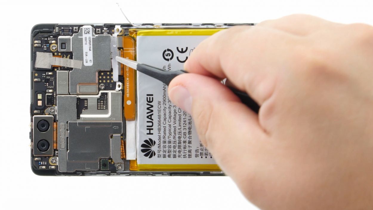
– Now, grab your trusty tweezers and gently remove the plate. Just a heads up, it’s secured on the motherboard at both the screw holes and in the center, so be a little careful.
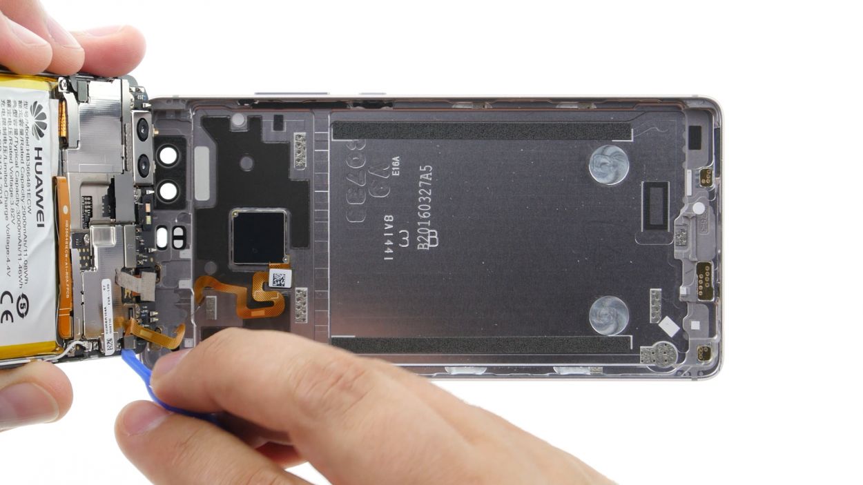
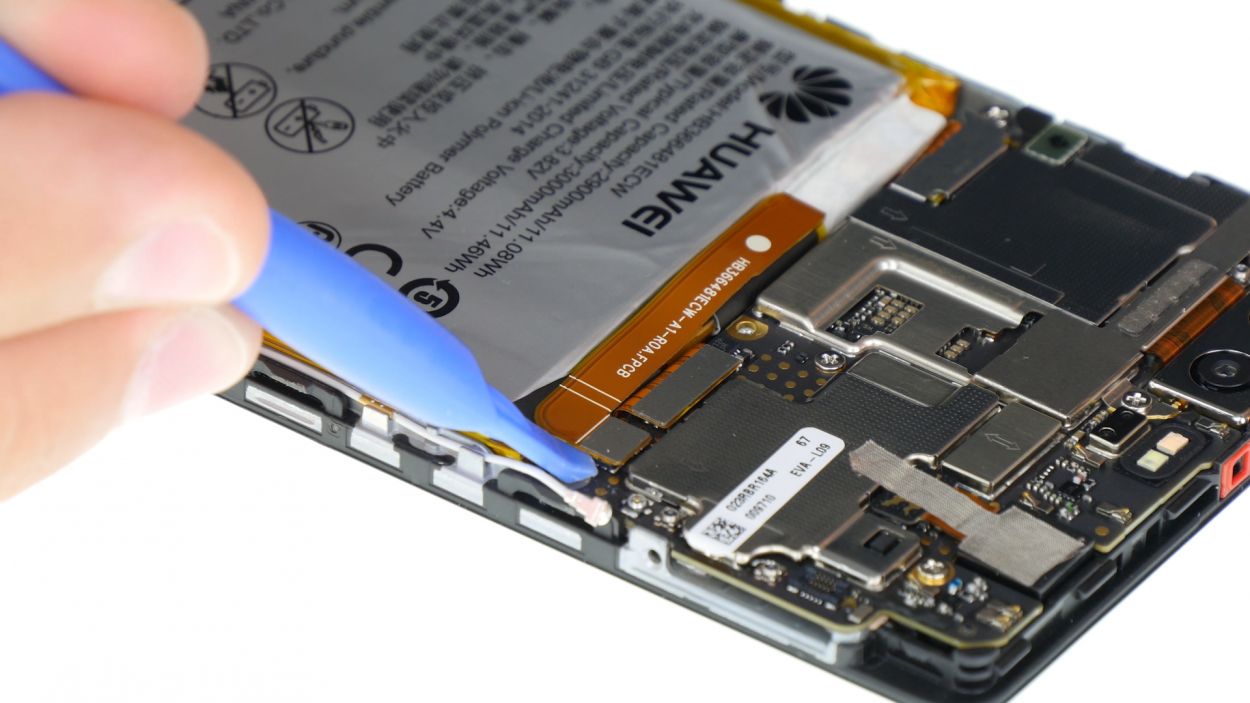
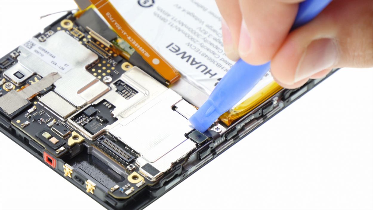
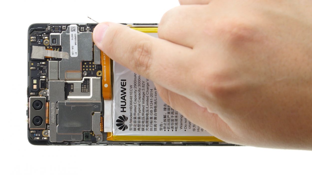
– Time to wield your spudger and delicately disconnect the battery contact. It’s like a gentle dance between tools!
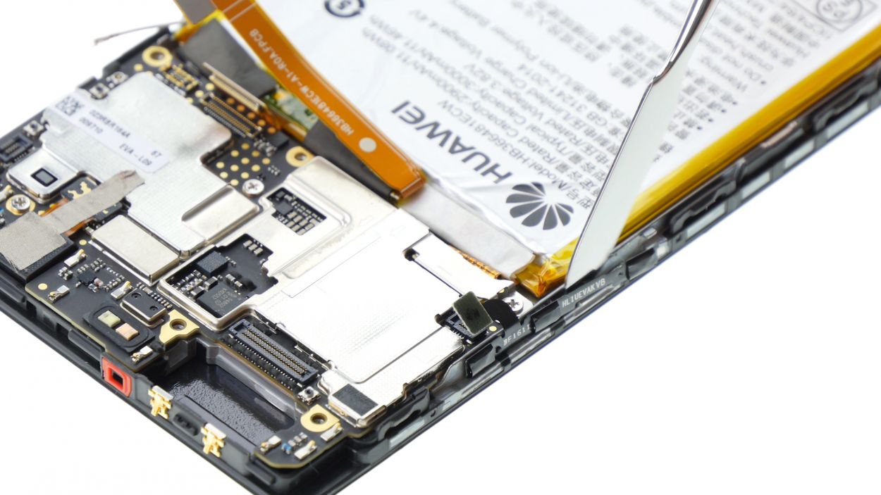
– Finally, disconnect the wide flexible flat cable that connects to the lower board from the motherboard. You’re almost there!
Step 6
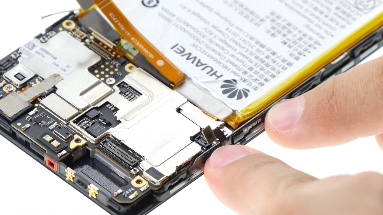
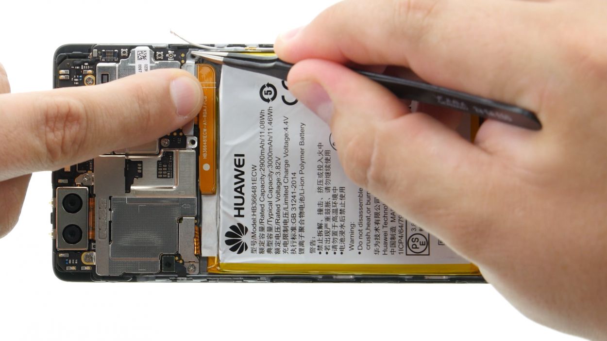
– Disconnect the connection, like a friend, from the motherboard.
– The control buttons have manners and don’t want to leave their home. Gently prod the steel spatula between the buttons and the frame. Start near one side as a gentleman.
– Then carry on to the other side, making sure not to disturb their tranquility.
– Remove the buttons, bowing out gracefully like a true friend.
Step 7
– Reattach the control buttons to the frame, using those handy little tabs for perfect positioning. Just slide those tabs through the round holes in the buttons and you’re golden!
– Give those buttons a firm press to ensure the glue sticks like a charm.
– Now, connect the plug contact to the motherboard and you’re on your way!
Step 8
2 × 2,5 mm PH00 Phillips-Schrauben
– Gently press the wide flexible flat cable into the motherboard’s socket until you hear a satisfying click. It’s like a little handshake!
– Next up, let’s reconnect that battery. It’s time to bring the power back!
– Now, carefully place the plate back on to secure those contacts. Make sure it hooks onto both the screw holes and in the middle for a snug fit.
– Tighten things up by fastening the plate with the two screws. You’re almost there!
– Lastly, connect the antenna cable to the motherboard. Let’s get those signals flying!
Step 9
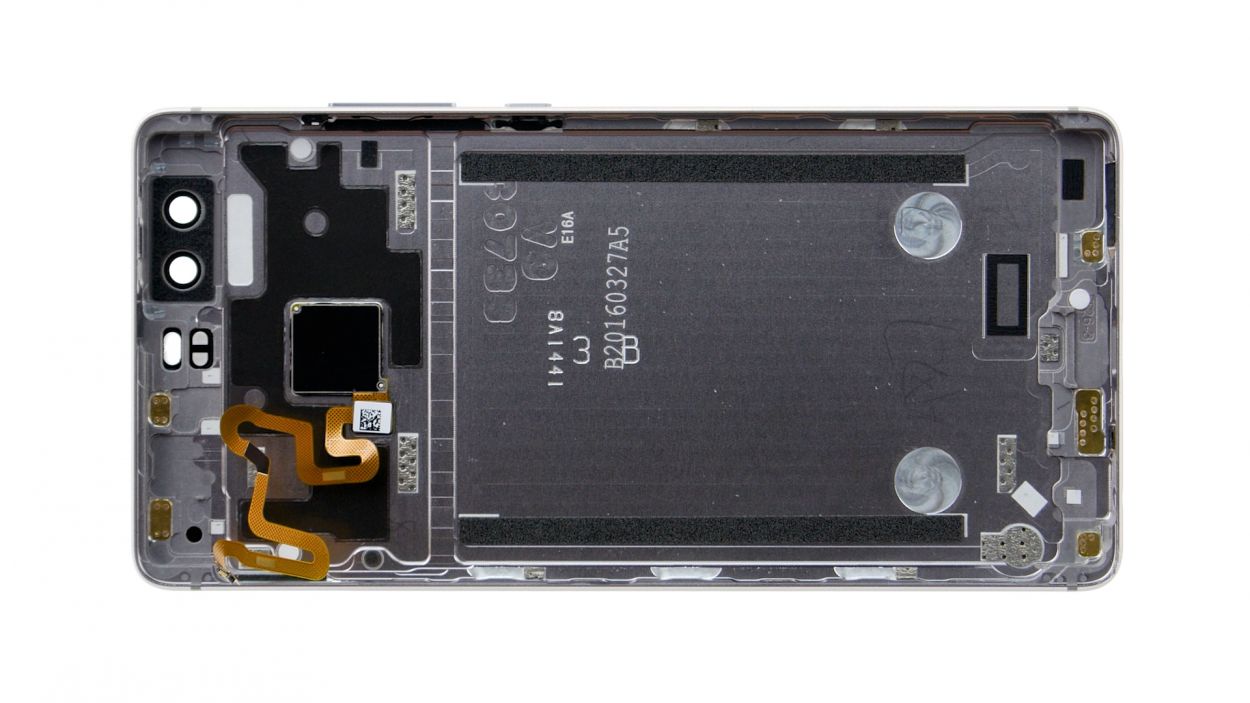
– Start by placing the back cover at the short upper edge of the display and gently connect the fingerprint sensor’s contact. Listen for that satisfying click as it locks into place!
– Next, fold down the back cover to close the device, giving the display a little press to make sure everything is snug and secure.
Step 10
2 × 2,8 mm P1 Pentalob-Schrauben
– Grab those two screws hanging out at the bottom edge of your device and screw them in to seal the deal!
Step 11
– Carefully slide the SIM tray and any cards back into your device. Just make sure the tray is aligned just right and you’re good to go!