How to Replace Huawei P9 Screen: Step-by-Step Guide
Duration: 45 min.
Steps: 38 Steps
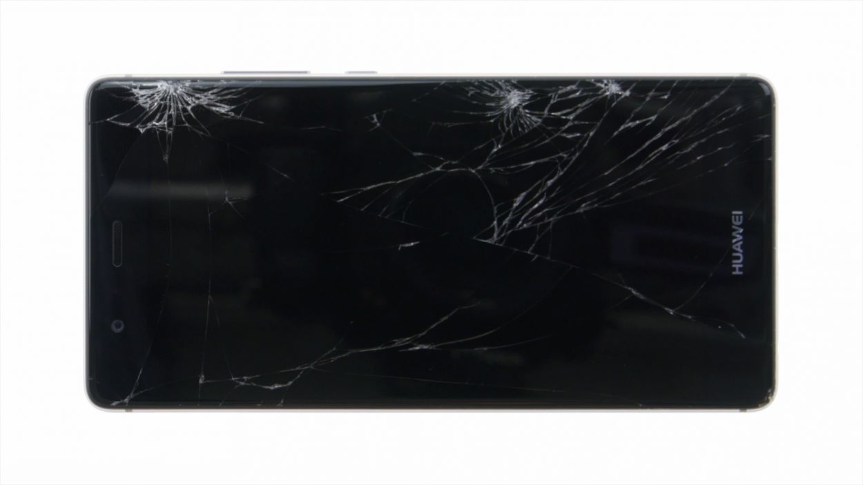
Ready to give your P9 a fresh new look? This guide is here to take you through the steps of swapping out that pesky broken display. Whether it’s sporting a spiderweb of cracks, being unresponsive to your touch, or just stays black or starts the disco flicker – we’ve got you covered!
Step 1
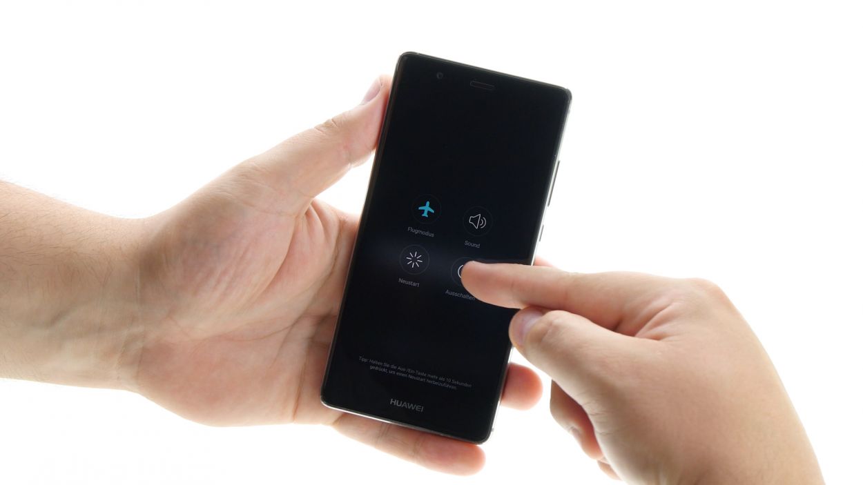
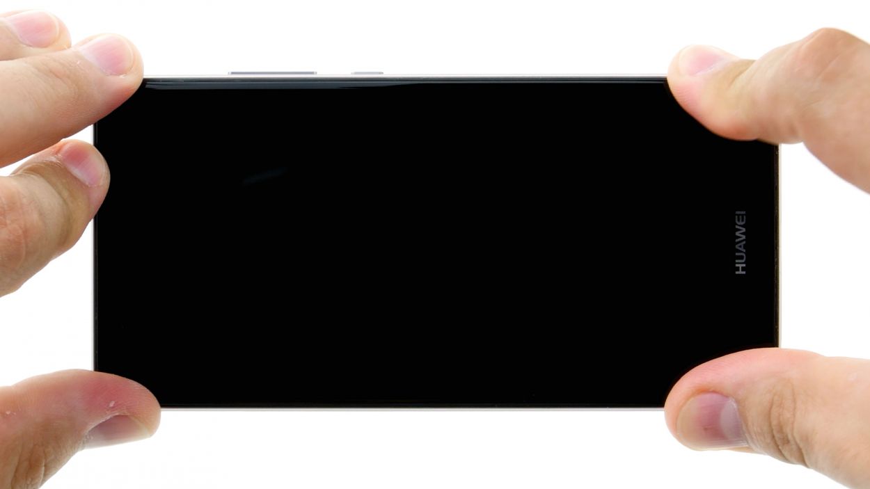
– Time to power down your gadget! Hold down the power button until a menu pops up. Choose ‘Power off’ and give it another tap to confirm.
Step 2
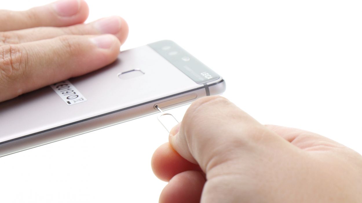
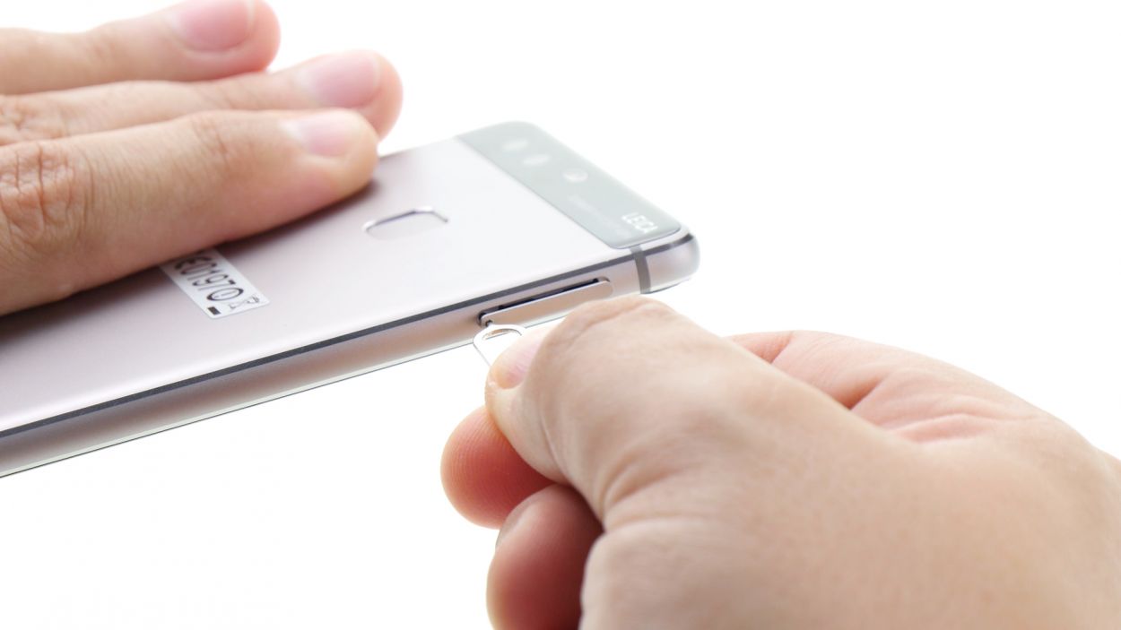
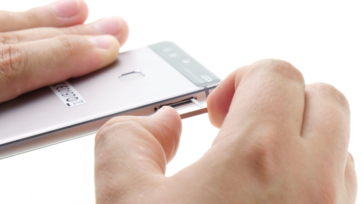
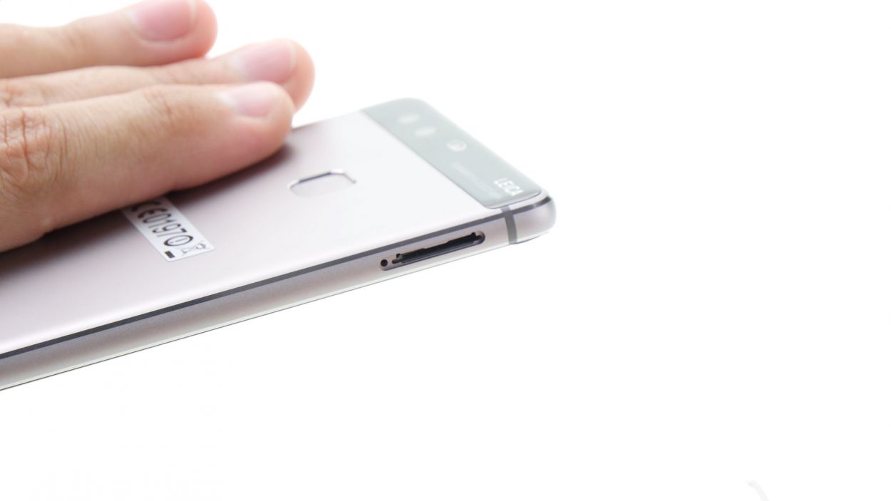
– Pop your SIM tool into the tiny hole on the tray to give it a gentle nudge and unlock it.
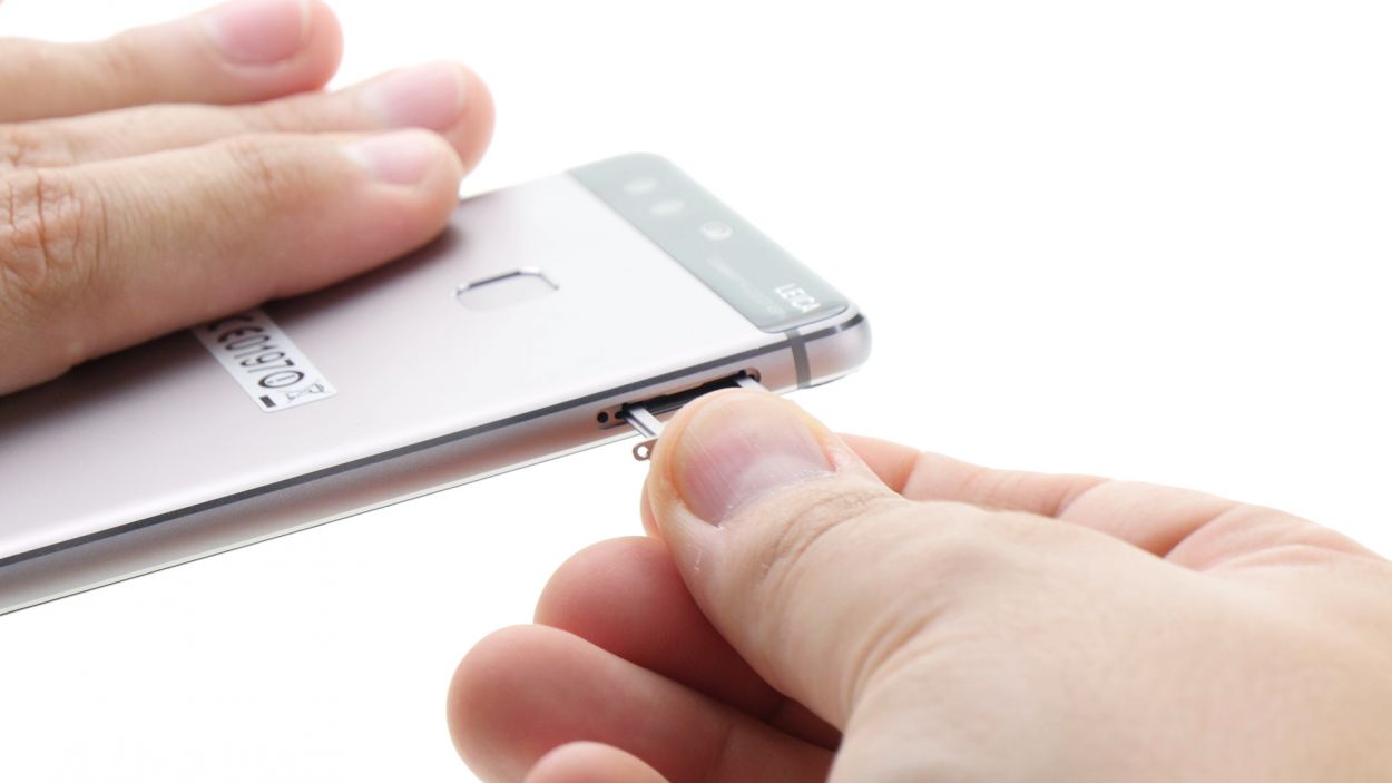
– Carefully pull out the SIM tray and, if you’ve got them, take out the SIM and microSD cards too.
Step 3
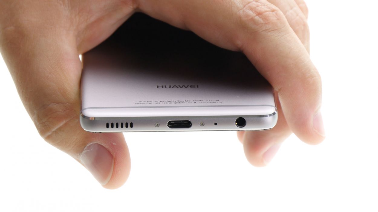
2 × 2,8 mm P1 Pentalob-Schrauben
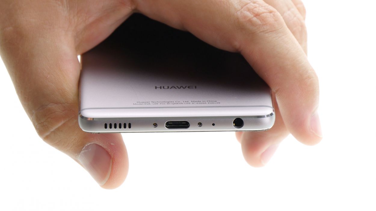
– Alrighty, let’s get this party started! Grab your trusty screwdriver and twist out those two little screws chilling at the bottom. They’re just hanging out there, keeping things together.
Step 4
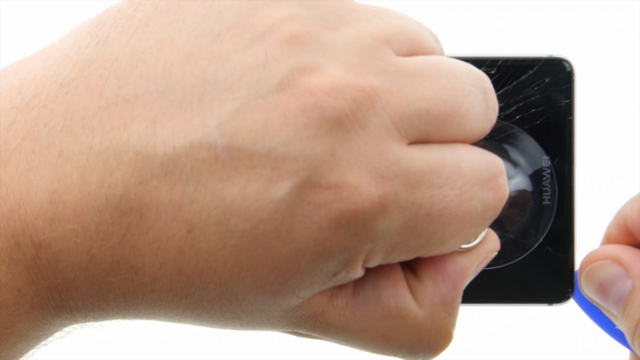
Hey there, friendly fixer! Just a heads up: watch your hands during this step – broken glass can be a real troublemaker. Rock those gloves or stick some tape over the display for a little extra protection!
– Position the suction cup as low on the display as you can—try right where it says ‘Huawei.’ If the glass is so cracked that the suction cup just won’t stick, grab some tape to cover that display.
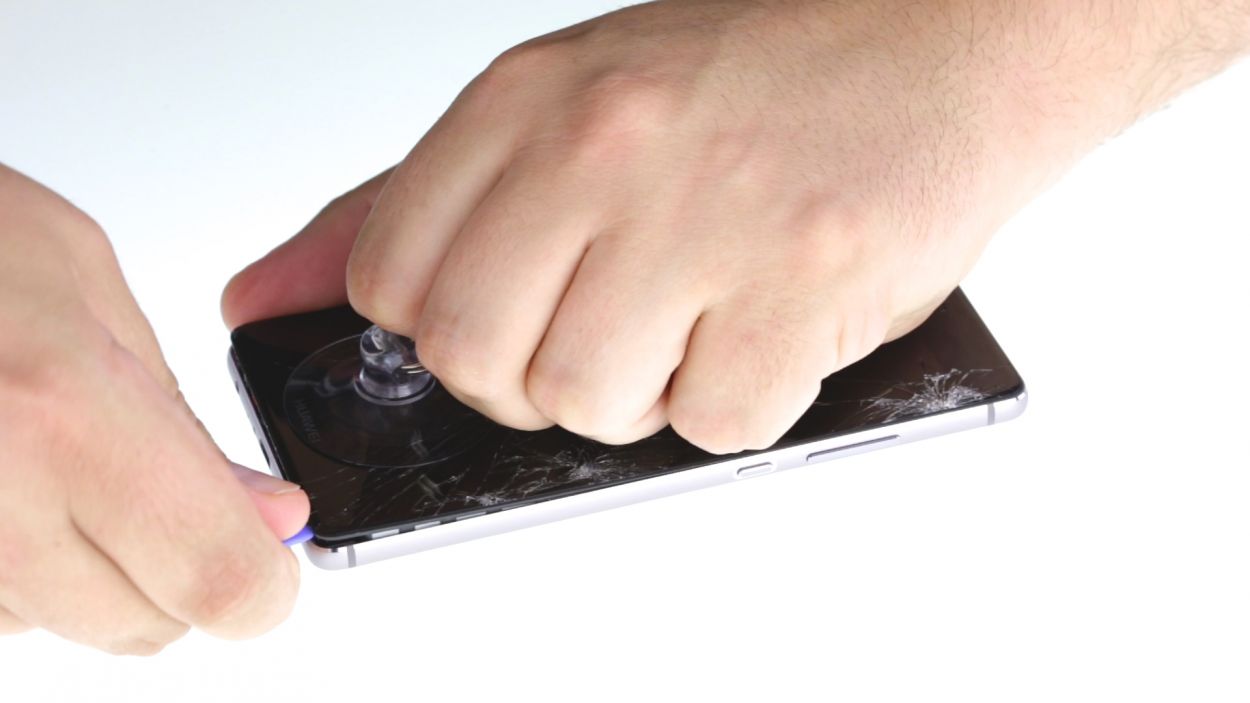
– Give the suction cup a gentle pull while using a pick to nudge the back cover against the table. Once you see a little gap forming between the display and the case, it’s time to delicately slide the pick in there.
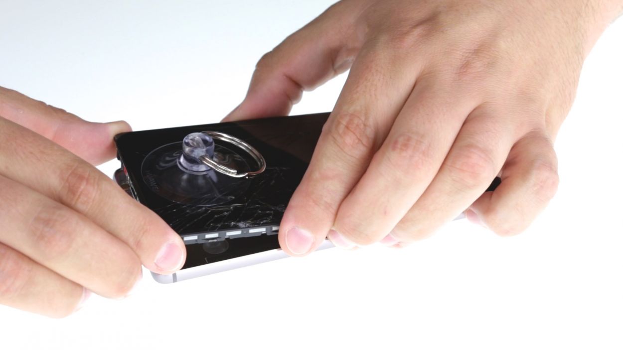
– Now, let’s glide that pick along the edges to free up the display from the sides. Keep pulling gently on that suction cup.
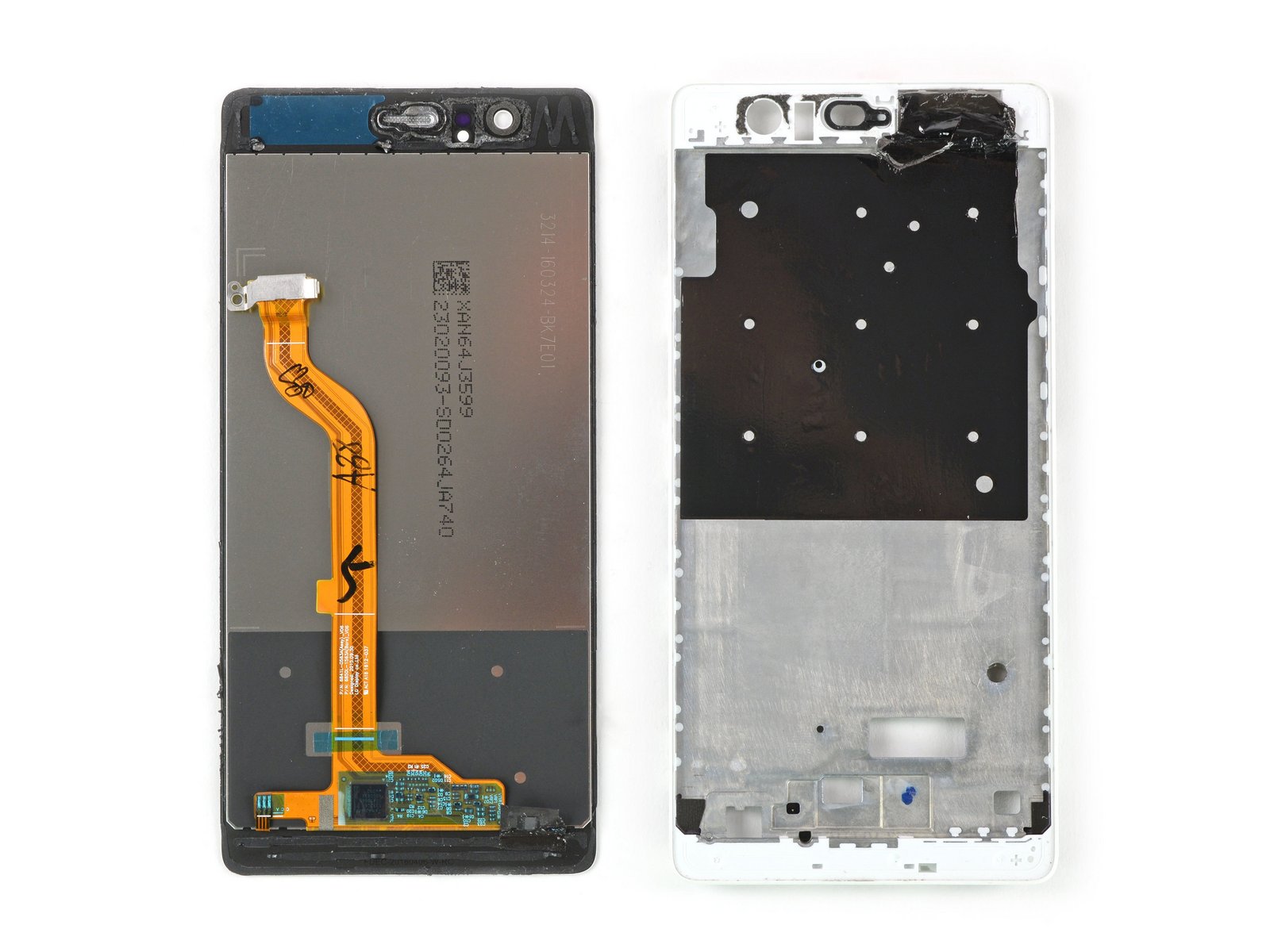
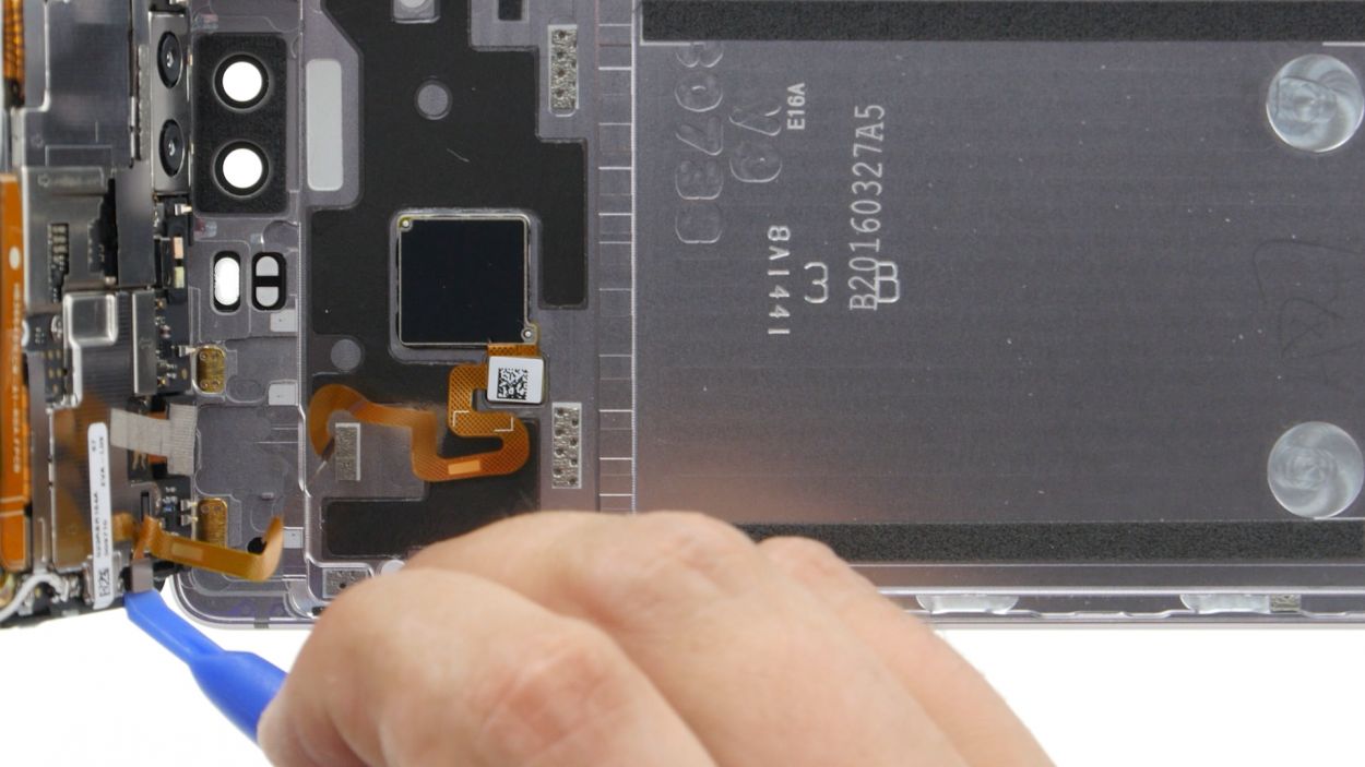
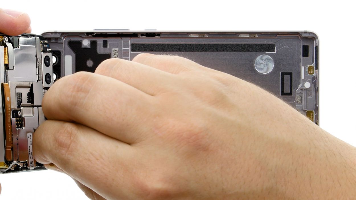
– Time to carefully lift the display! Open your device from the short top edge like you’re flipping a book’s page. You should now be able to spot the connection cable.
– For the next step, let’s disconnect the cable from the motherboard. Use the spudger to gently slide it underneath the connector and disconnect it.
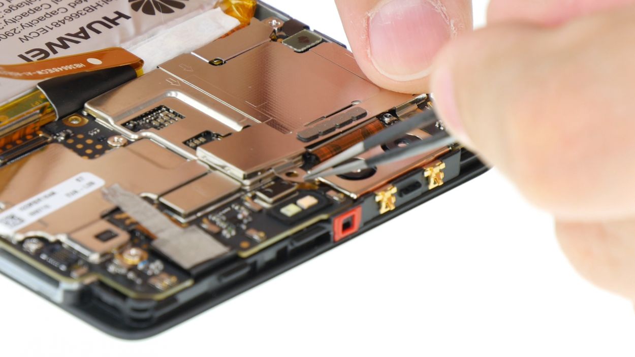
Step 5

2 × 2,5 mm PH00 Phillips-Schraube
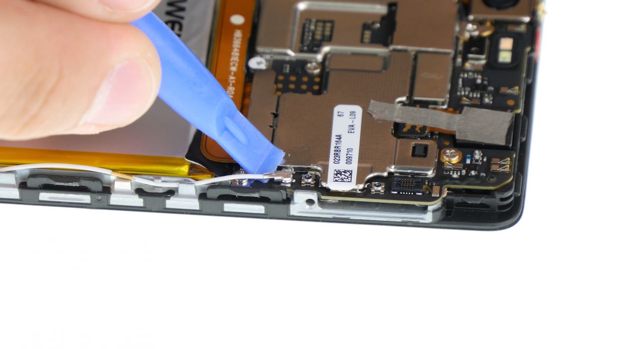
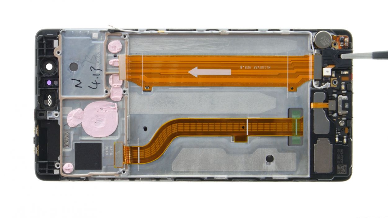
Antenna Cable
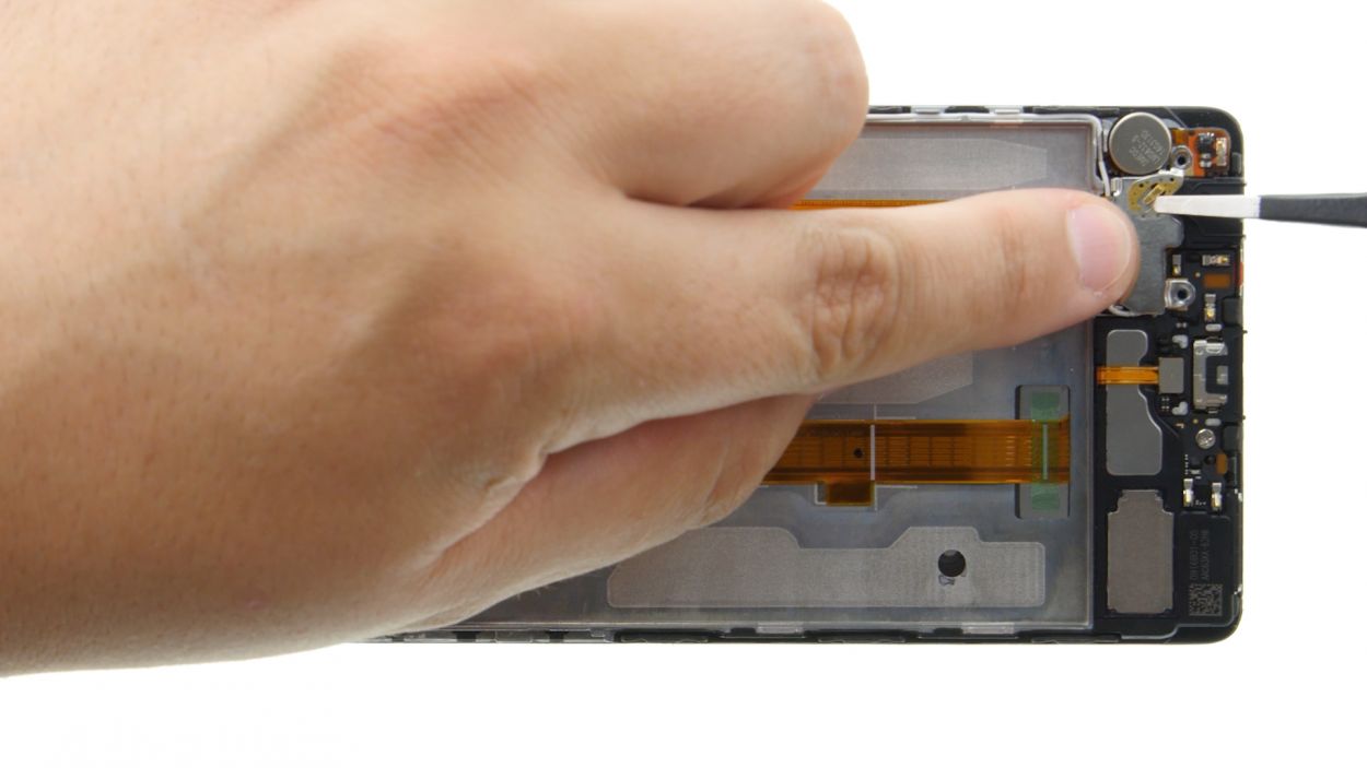
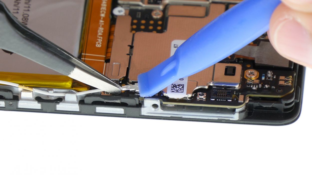
– First up, gently unplug the white antenna cable from the motherboard to reveal the hidden screw waiting for you underneath.
– Next, it’s time to unscrew! Remove those two screws that are keeping the plate snug in its spot.
– Now, grab your trusty tweezers and delicately lift off the plate. It’s attached to the motherboard at both the screw holes and the center, so be gentle.
– With your spudger in hand, carefully disconnect the battery contact. You got this!
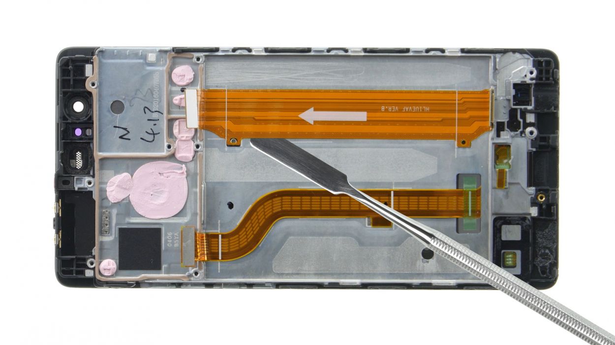
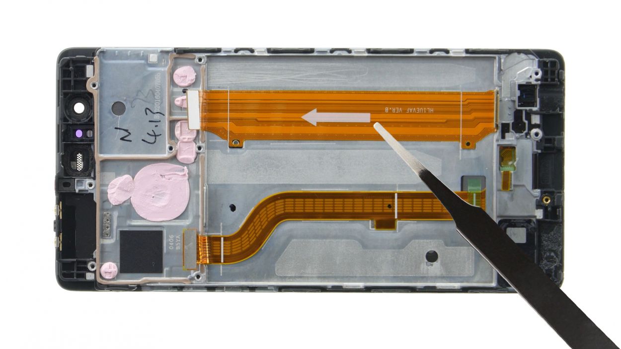
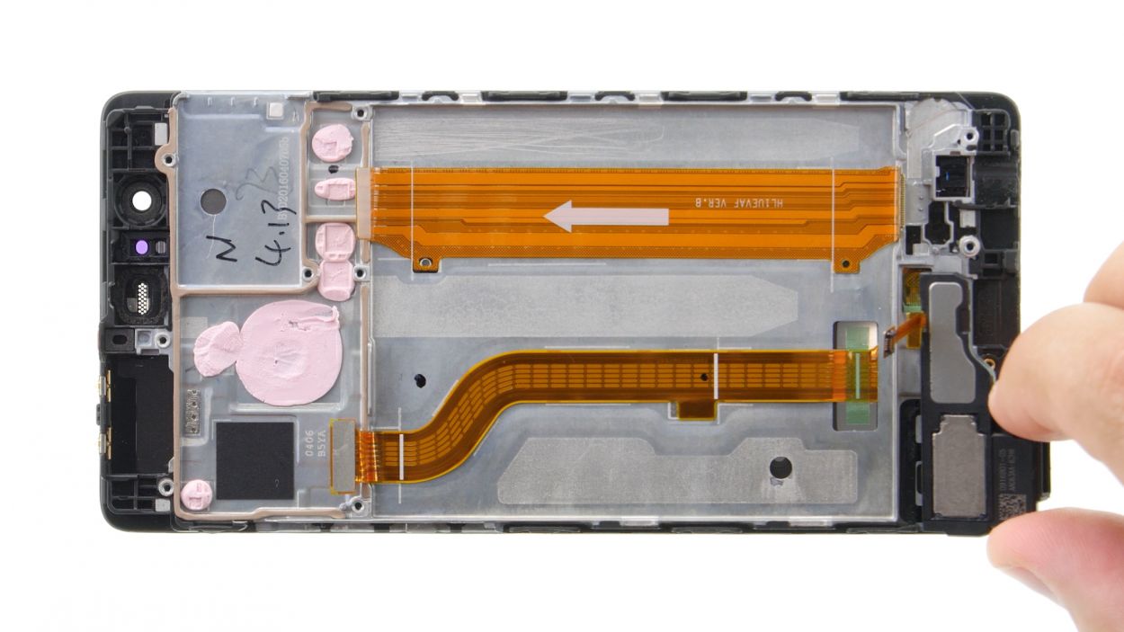
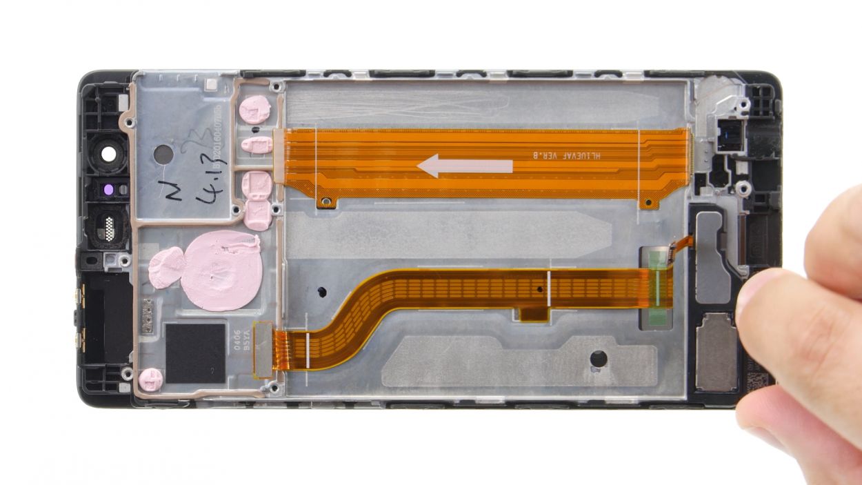
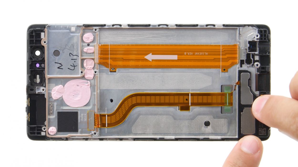
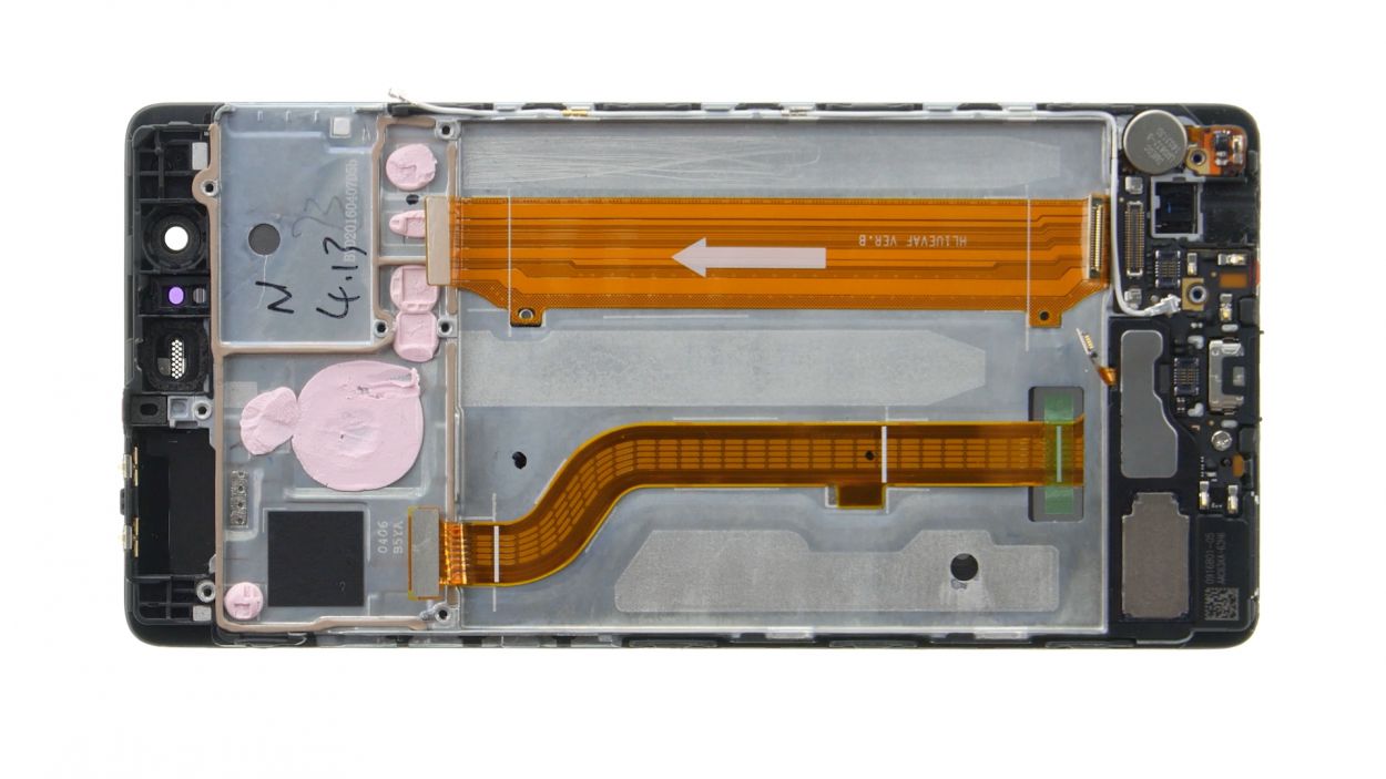
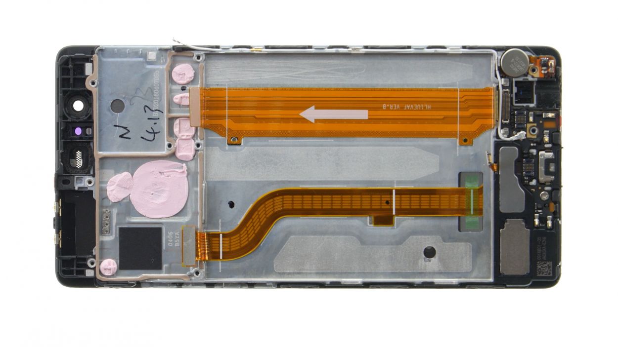
– Finally, disconnect the wide flexible flat cable that connects to the lower board from the motherboard. Almost there!
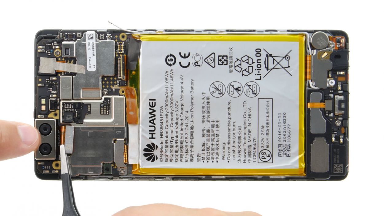
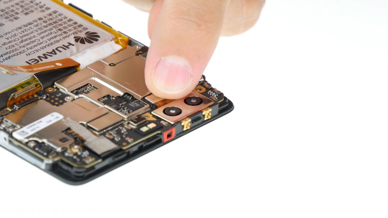
Step 6

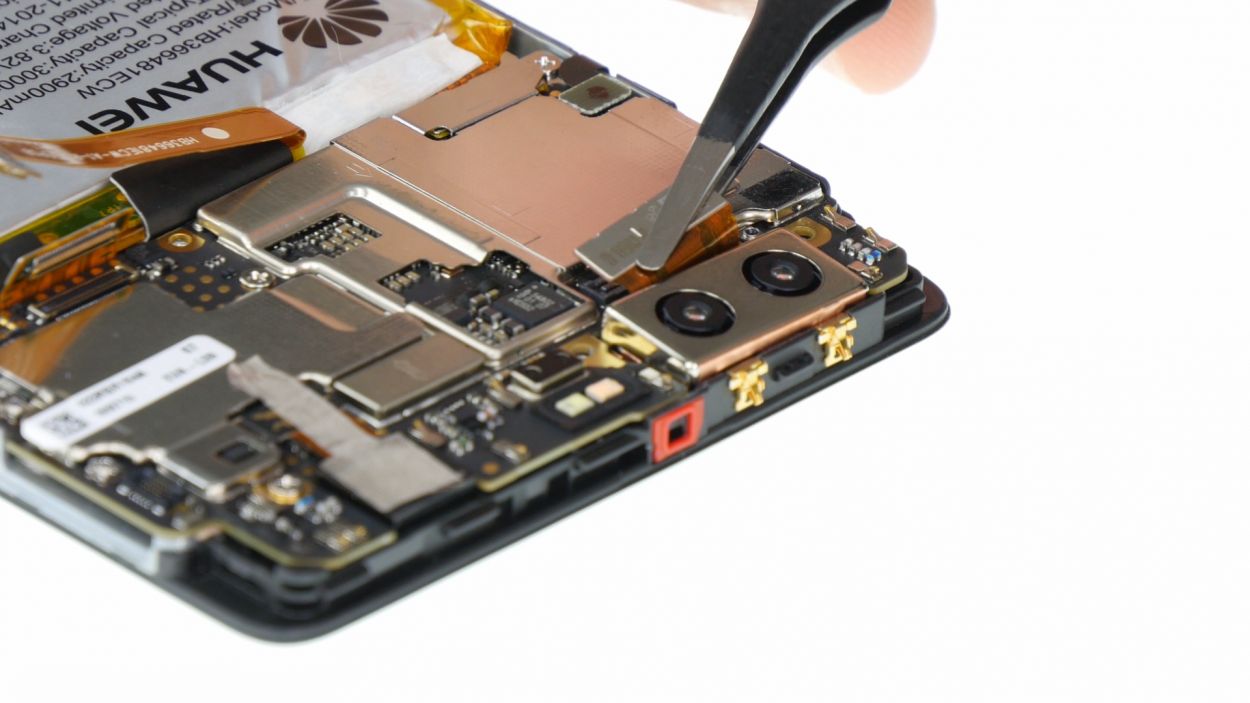
2 × 2,5 mm PH00 Phillips-Schrauben
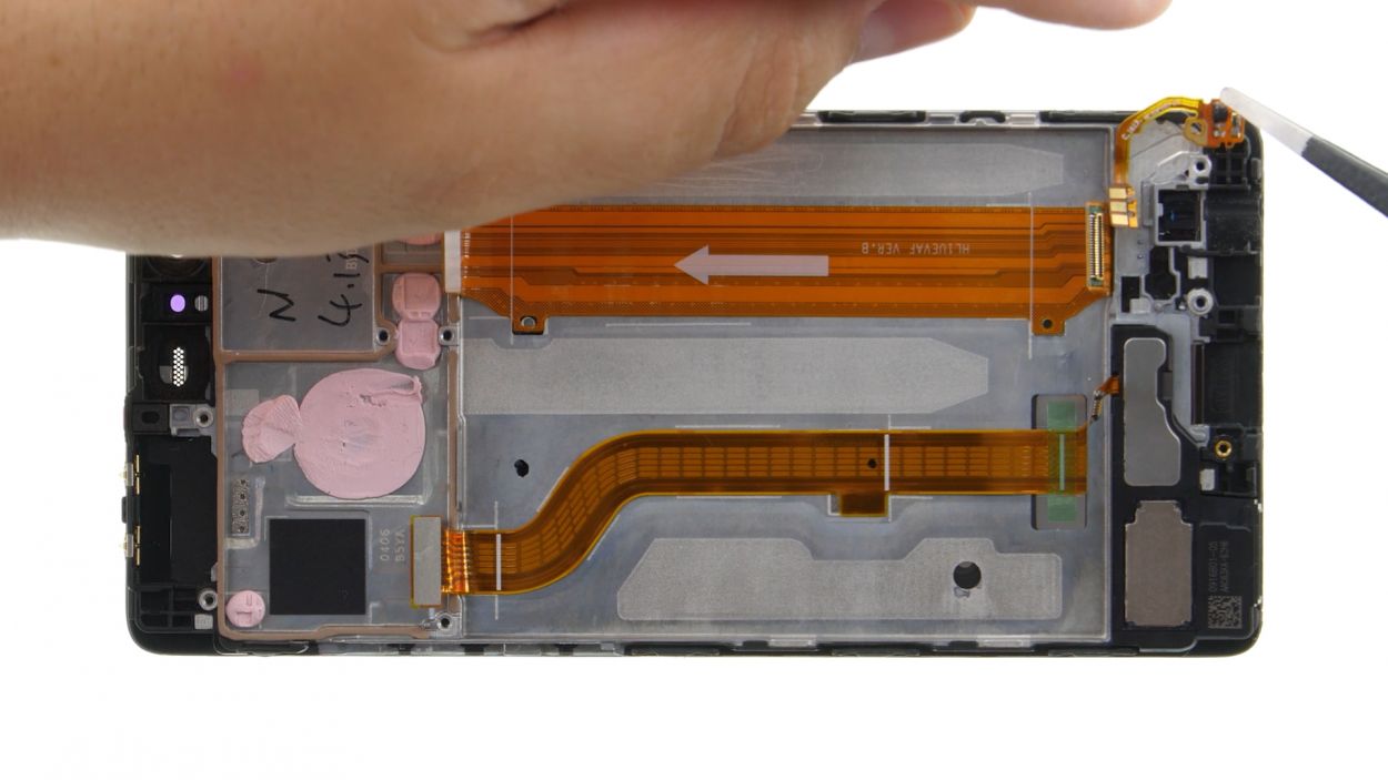
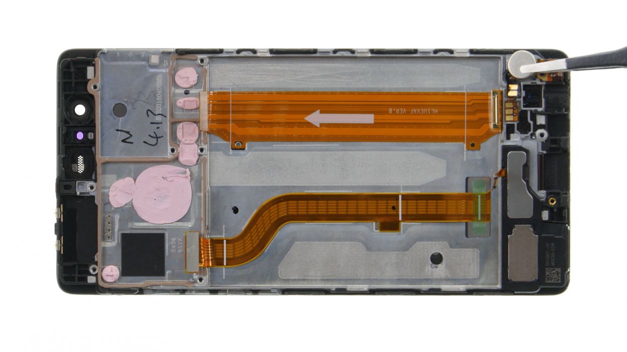
– First things first, buzz over to those two pesky screws holding the plate down and remove them.
– With the screws out of the way, gently lift off the plate and set it aside.
– Now, grab your trusty spudger and sneak it underneath the camera’s plug contact to disconnect it from the motherboard.
– Finally, carefully take out the camera from its cozy enclosure.
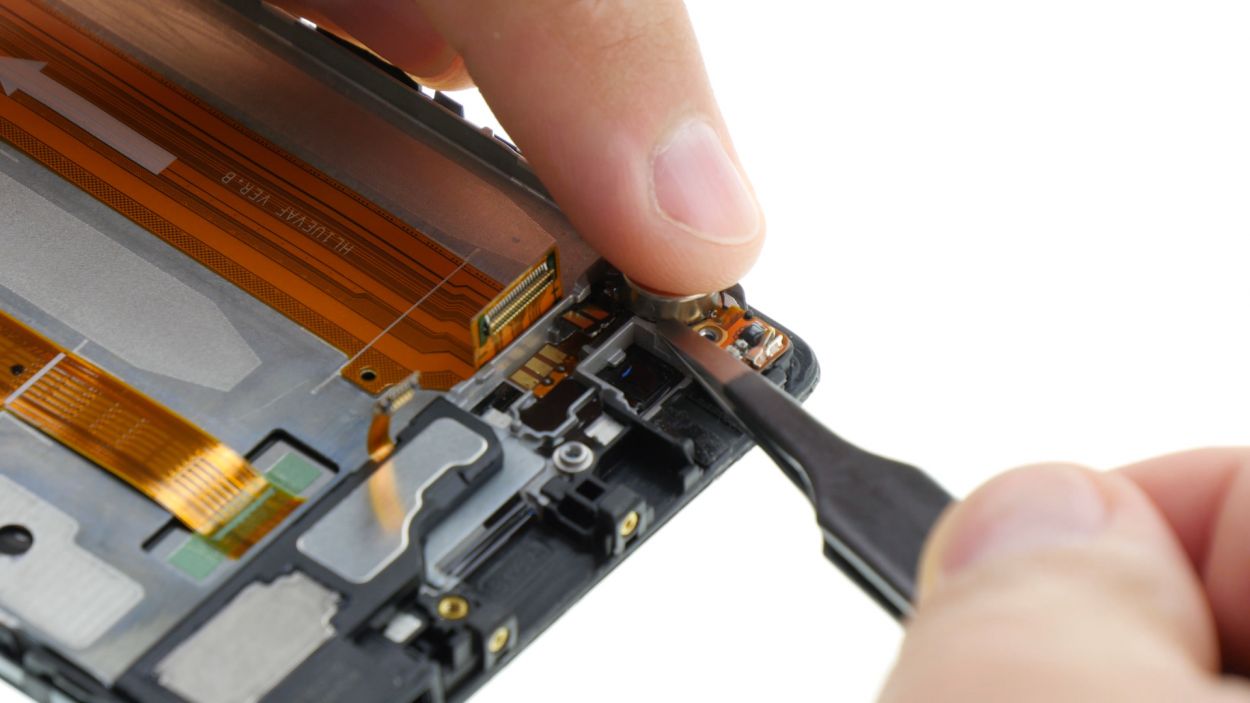
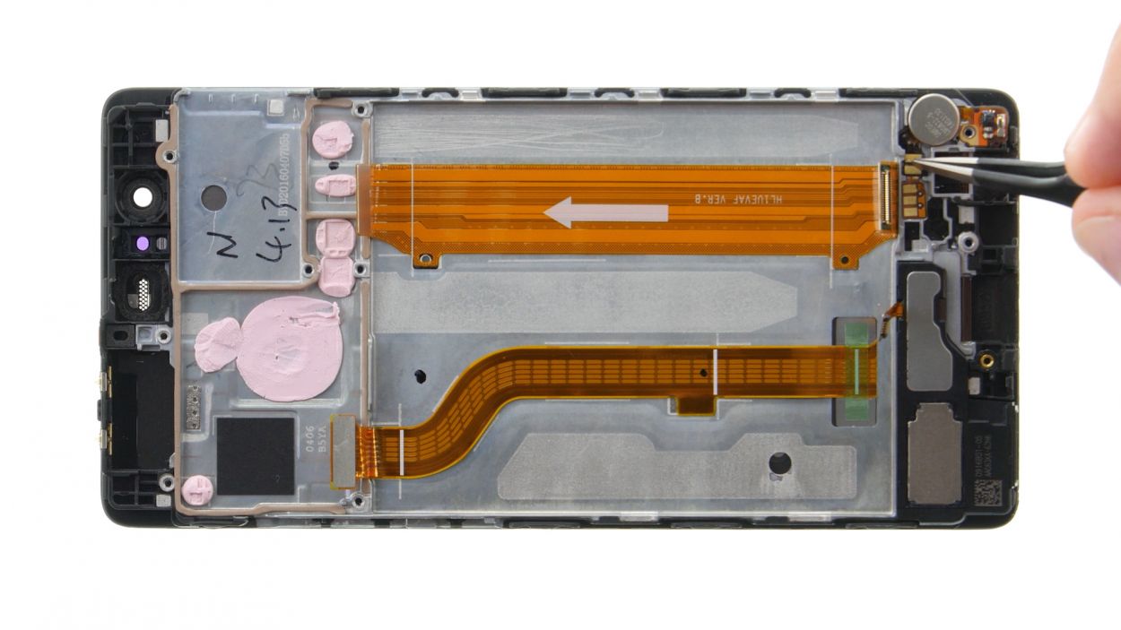
Step 7
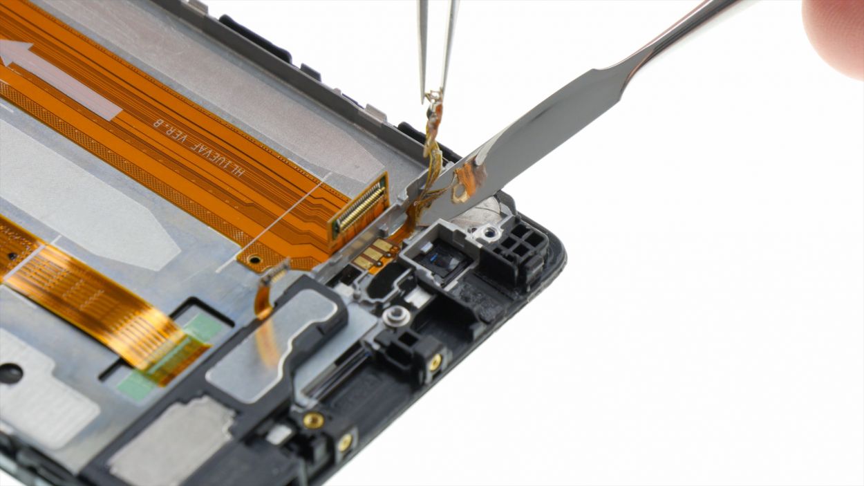
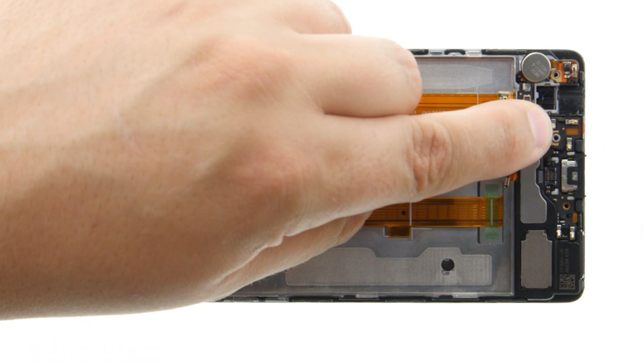
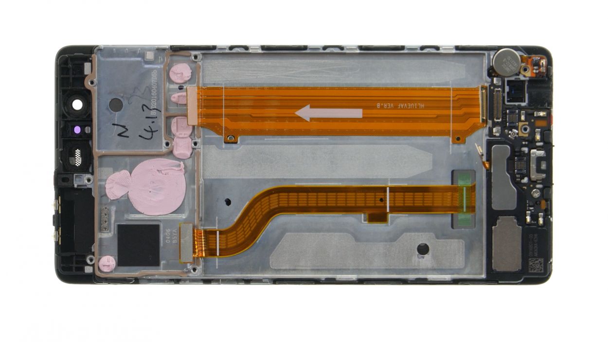
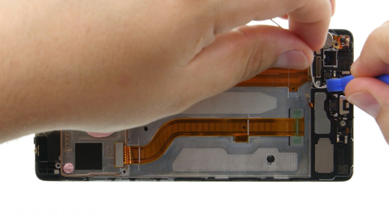
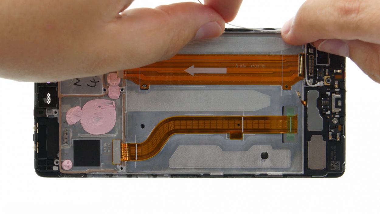
– First, break up with your motherboard – unplug any connections.
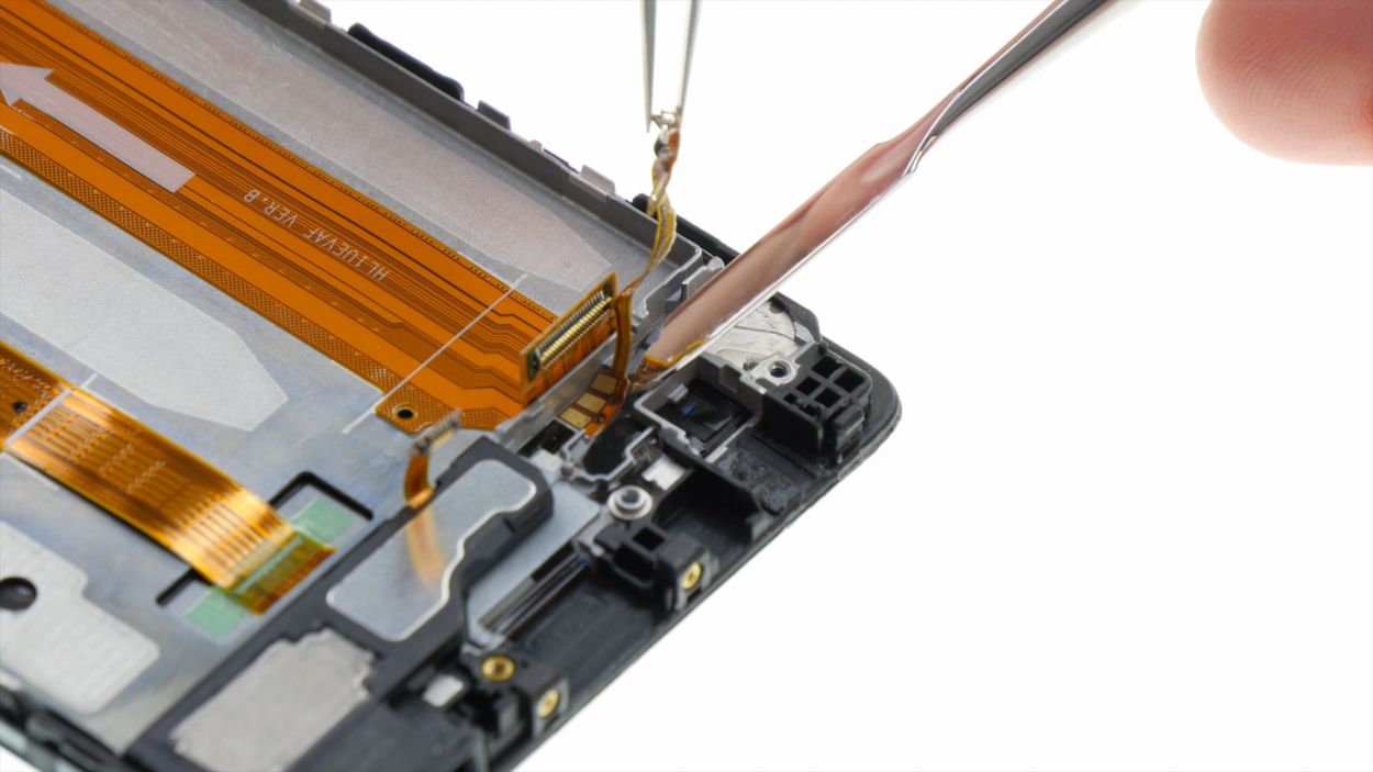
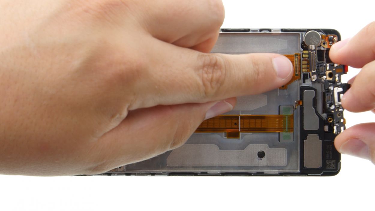
– Next, those control buttons are sticking too close to the display frame. Grab your steel spatula and gently slide it between the stubborn buttons and the frame. Begin on one side and show ’em who’s boss.
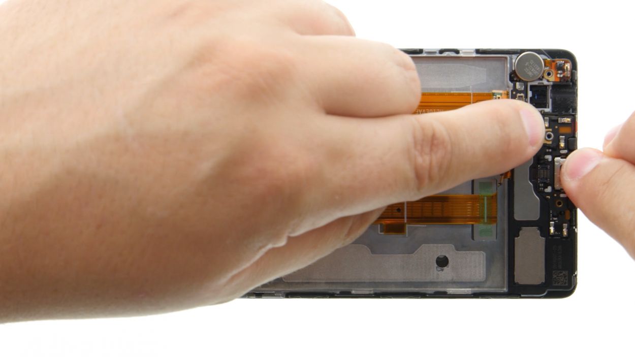
– Once you’ve got one side loose, flaunt the same moves on the other side.
– Now, just whisk those buttons away. Ta-da!
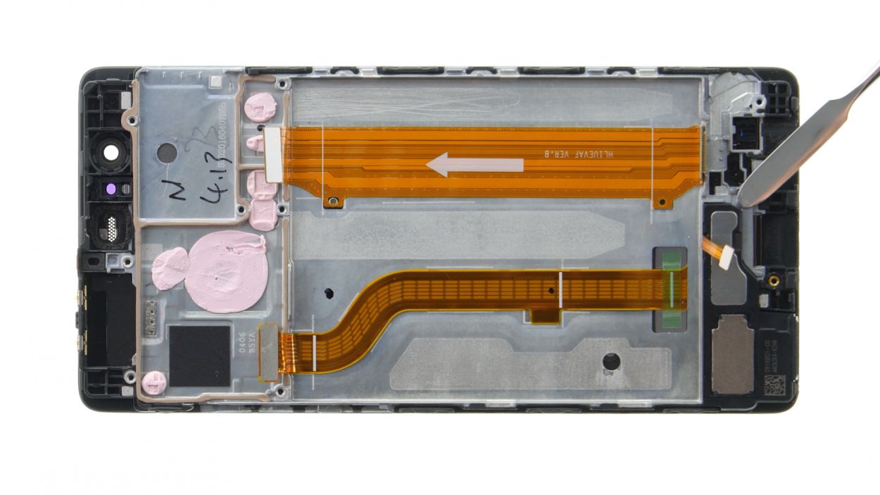
Step 8
1 × 2,5 mm PH00 Phillips-Schraube
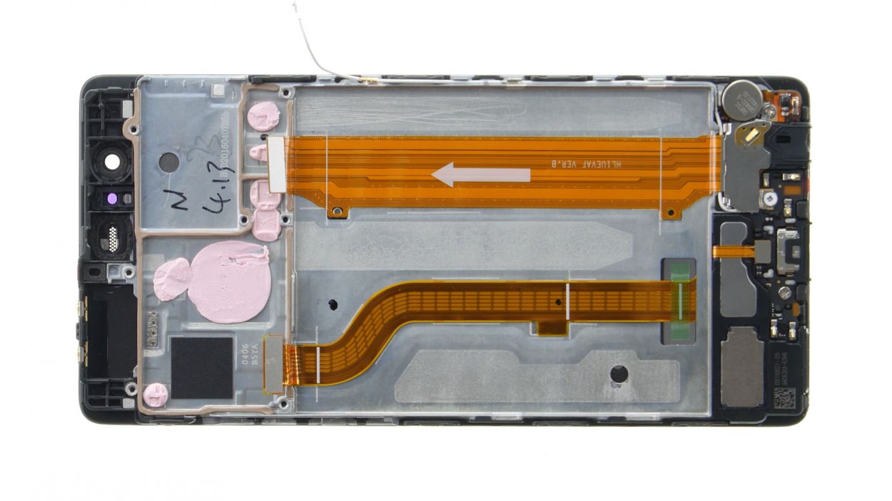
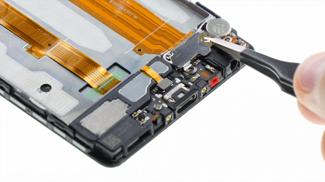
Step 9
2 × 2,5 mm PH00 Phillips-Schrauben
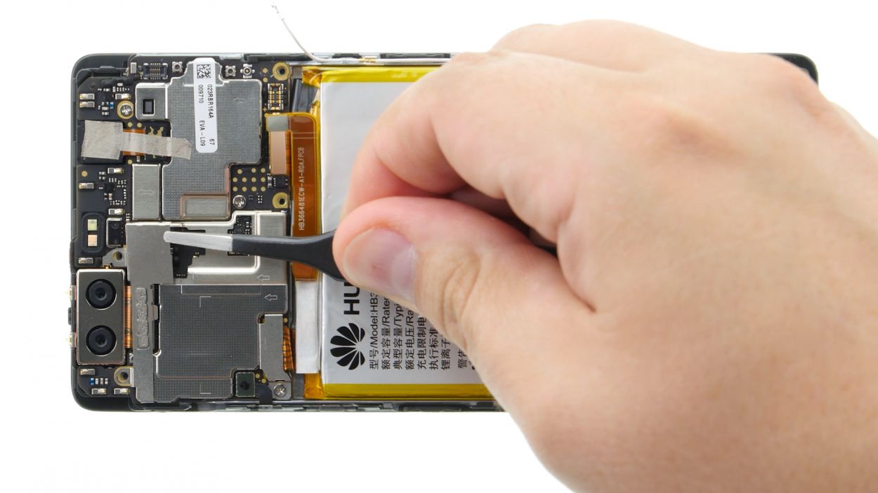
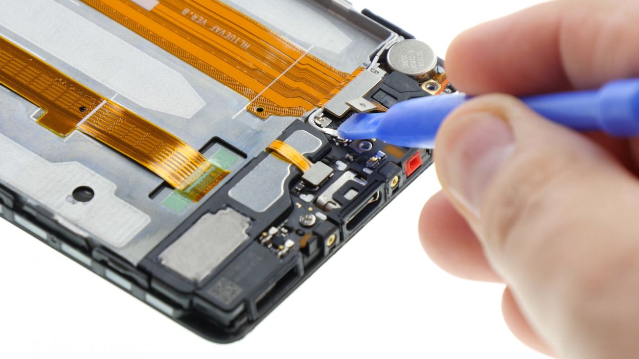
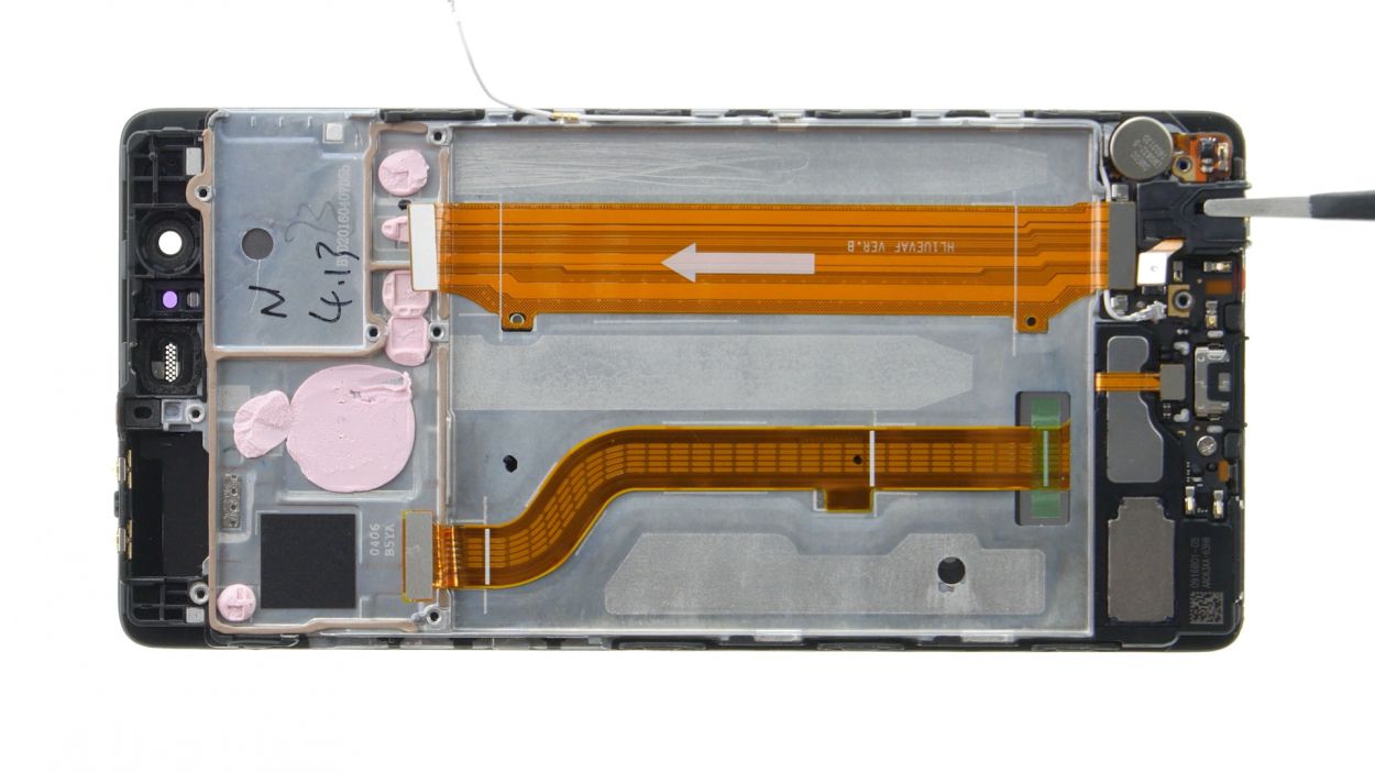
– First up, we’ve got two screws holding the motherboard snug in its cozy enclosure. Let’s get those screws out!
– Next, the board is also giving a little hug to the enclosure. Grab your trusty spudger and slide it in the middle of the right side to gently release it.
– Now, pop that spudger into the upper left corner and carefully pry out the board. You’ve got this!
– Finally, say goodbye to the board as you remove it. You’re making great progress!
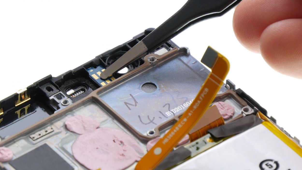
Step 10
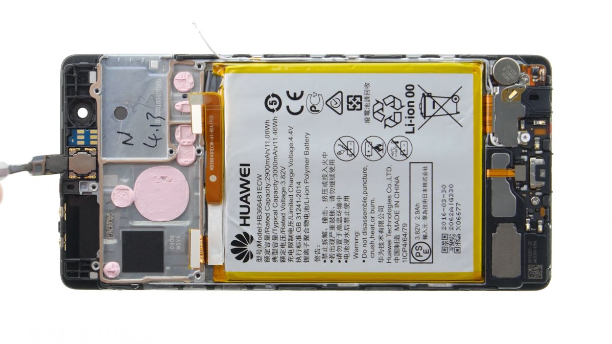
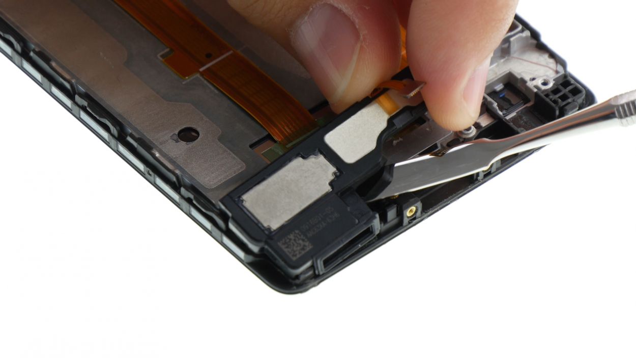
– The earpiece is snugly glued in there, so let’s gently coax it out with a steel spatula. Slide the spatula in from the top and carefully pry it loose.
– Once you’ve got it moving, just lift the earpiece out of its cozy little spot in the enclosure.
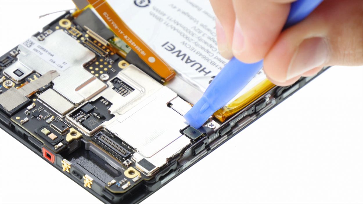
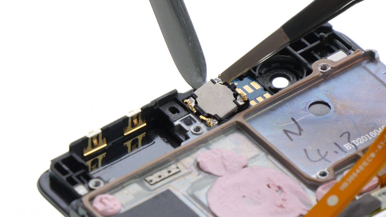
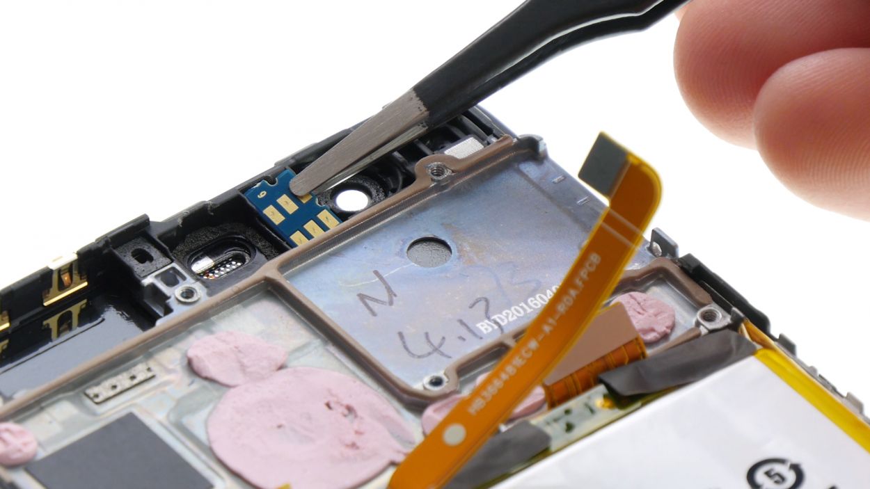
Step 11
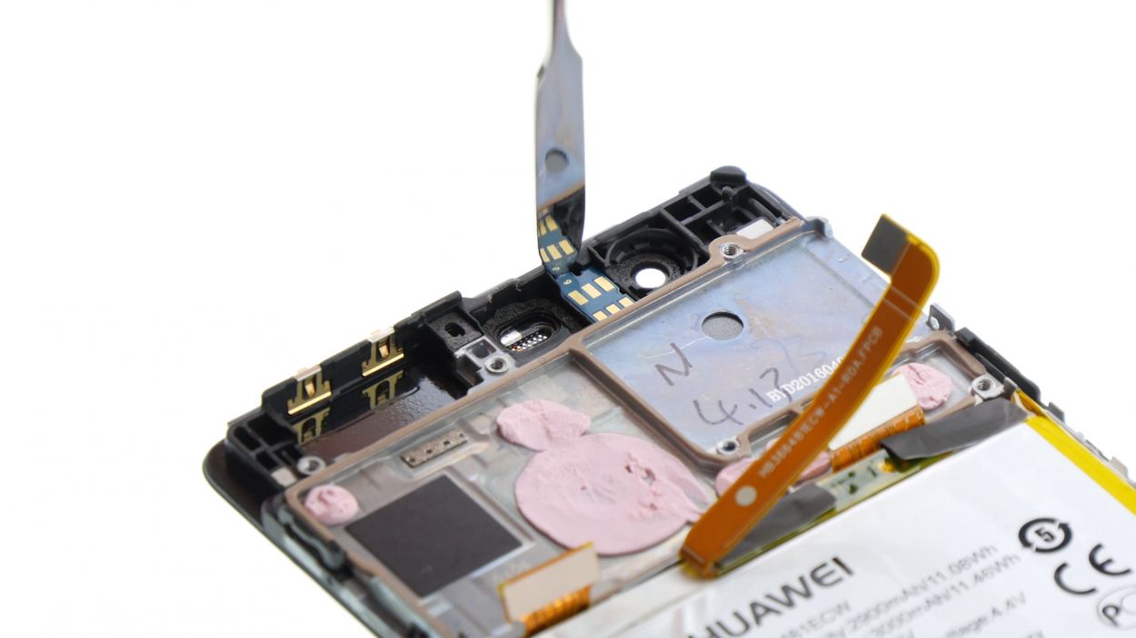
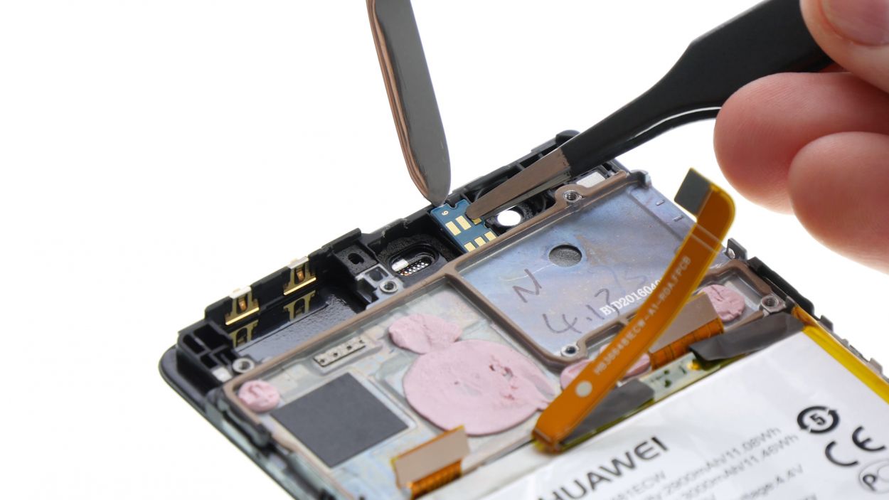
– The proximity sensor loves to stick around, so let’s help it say goodbye! Gently slide the spatula in from the top to coax the sensor off the enclosure.
– Now, go ahead and pull out the proximity sensor!
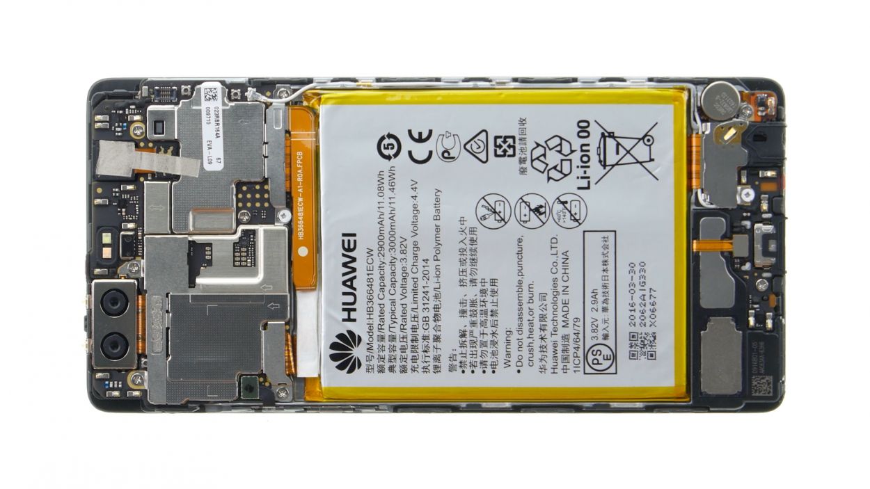
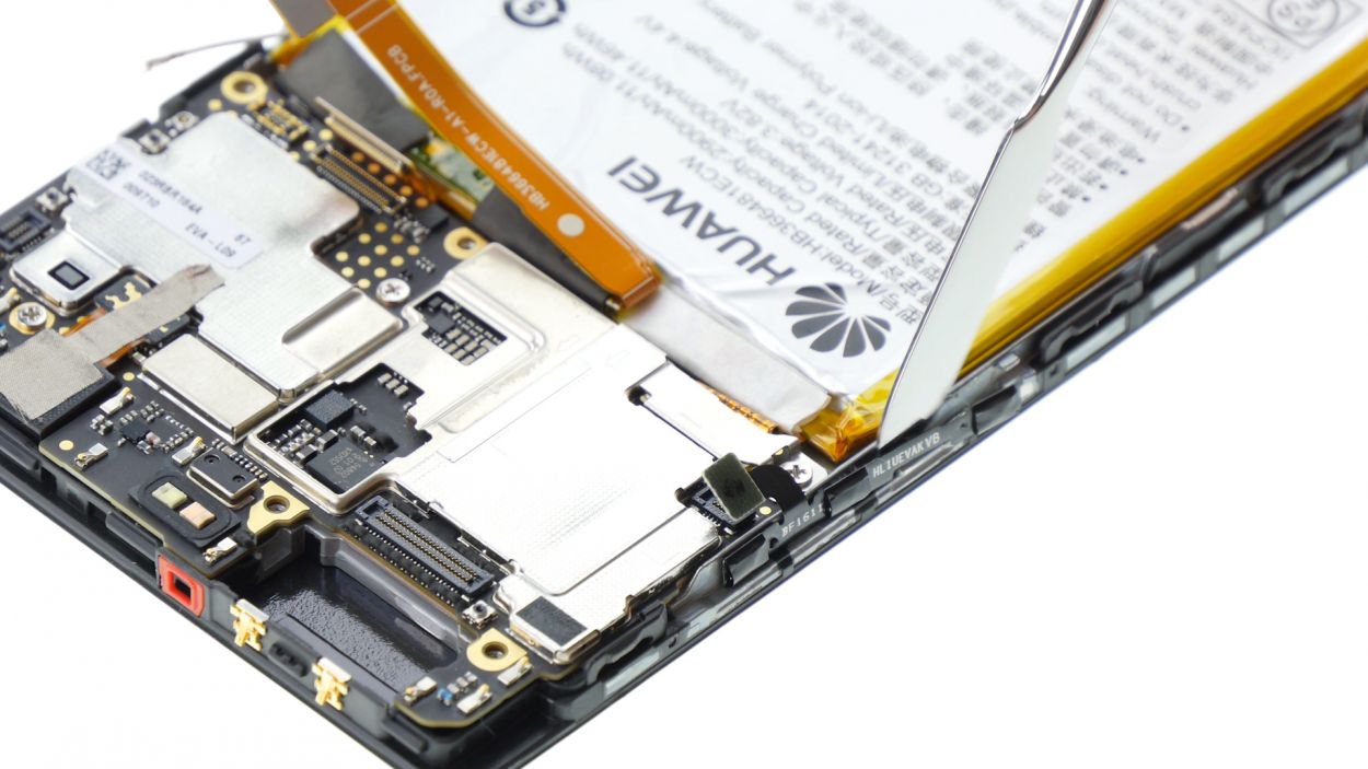
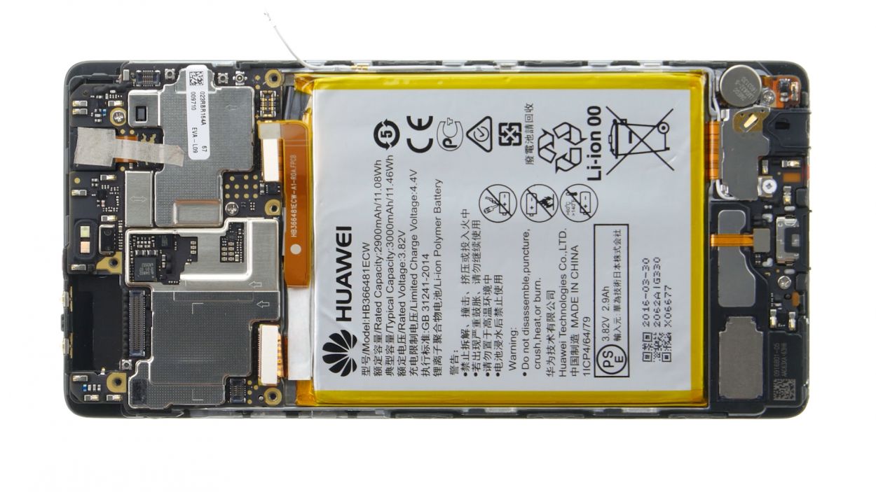
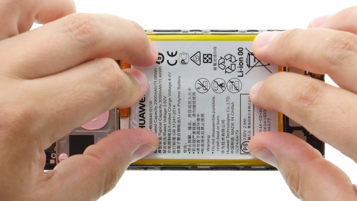
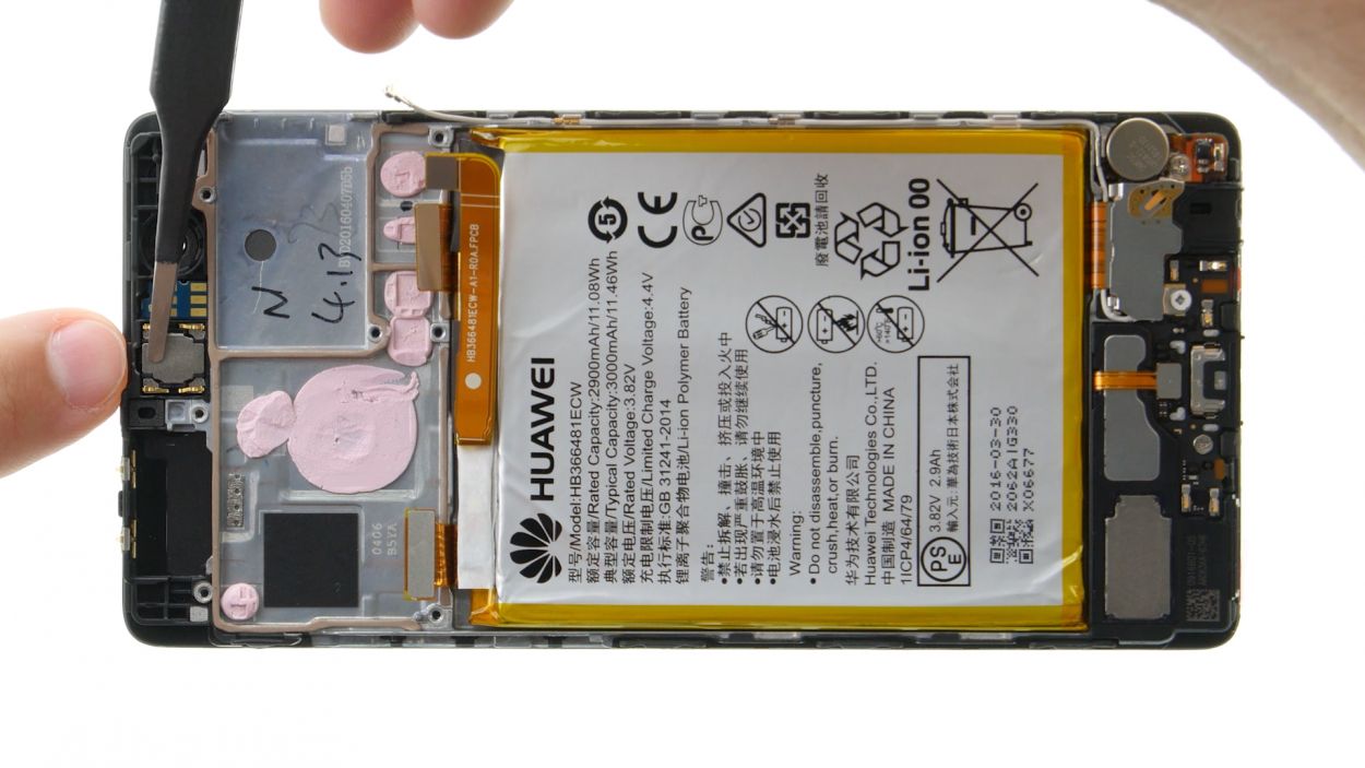
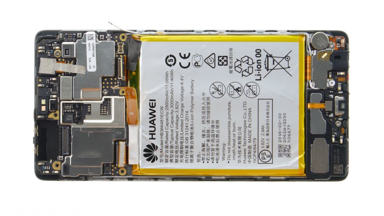
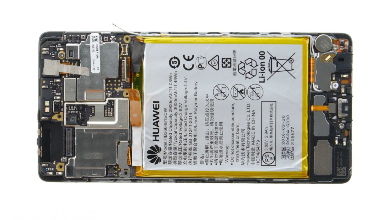
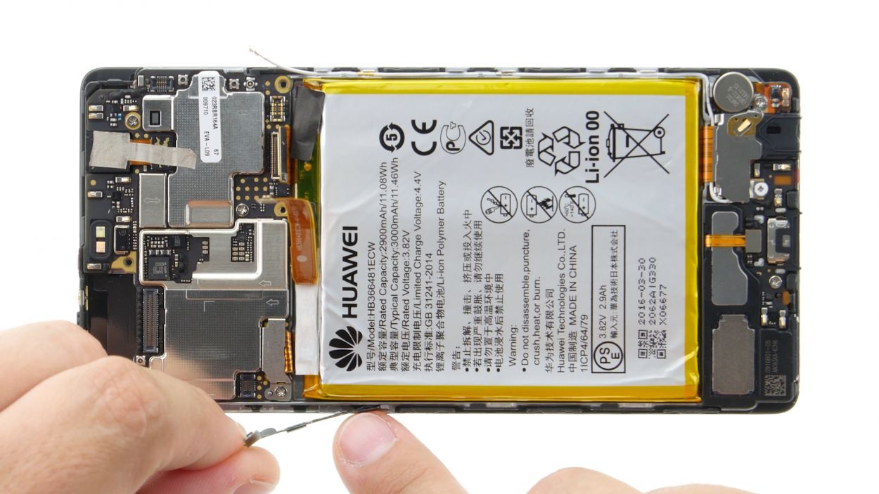
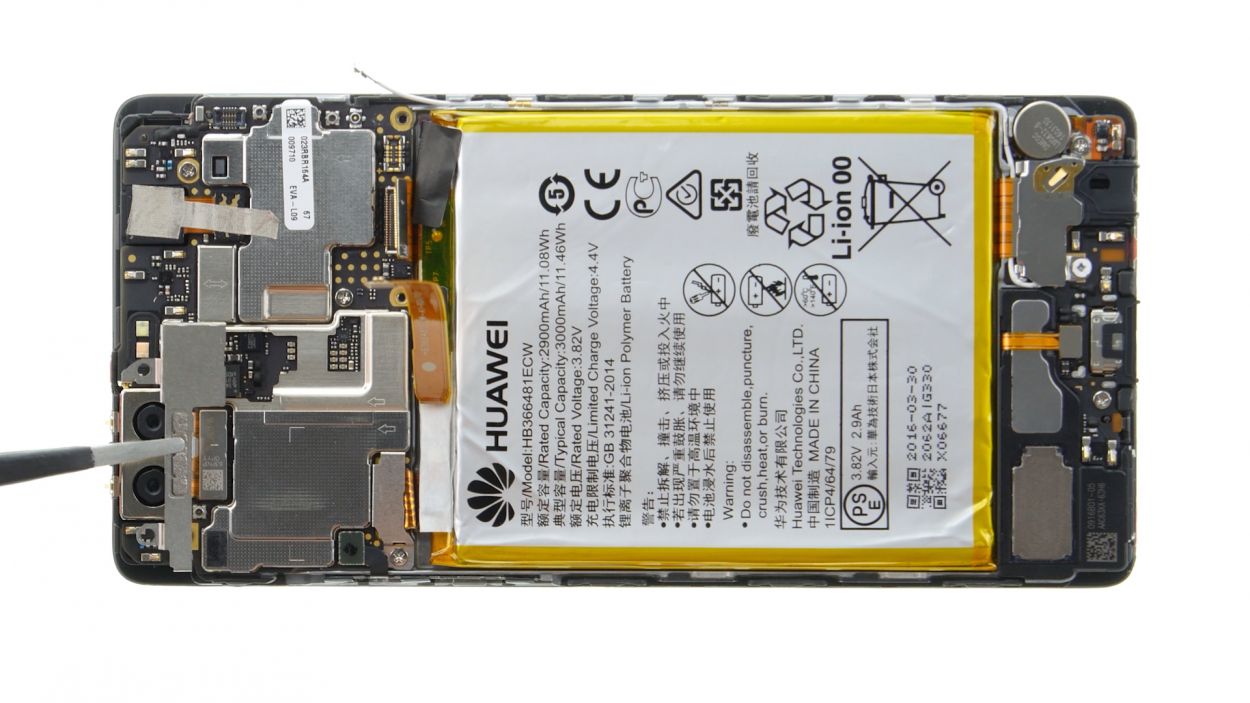
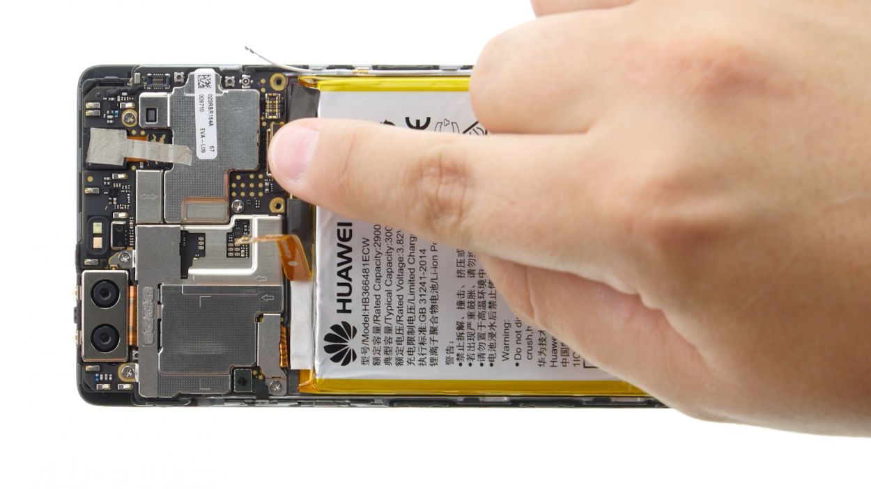
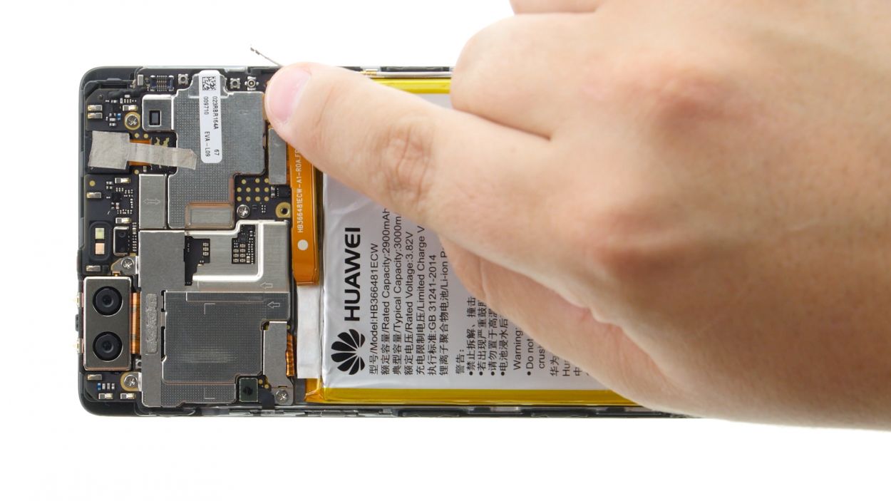
Step 12
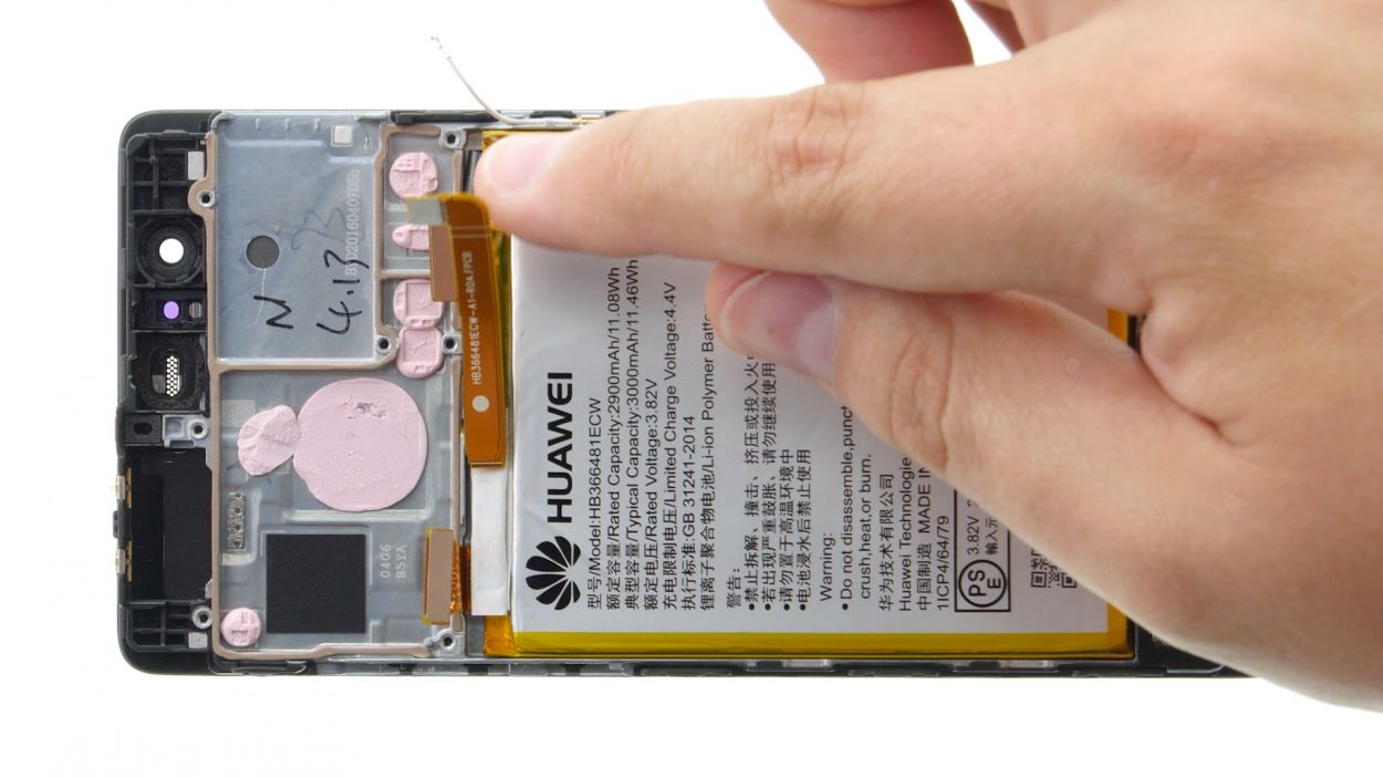
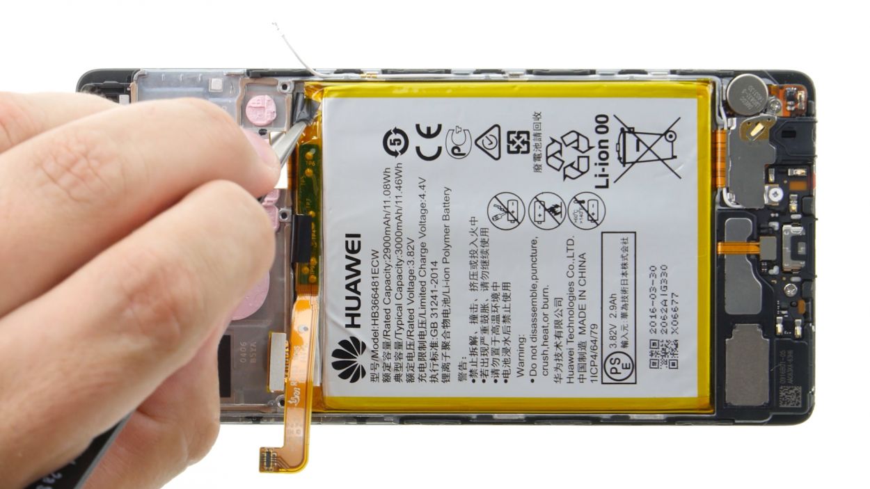
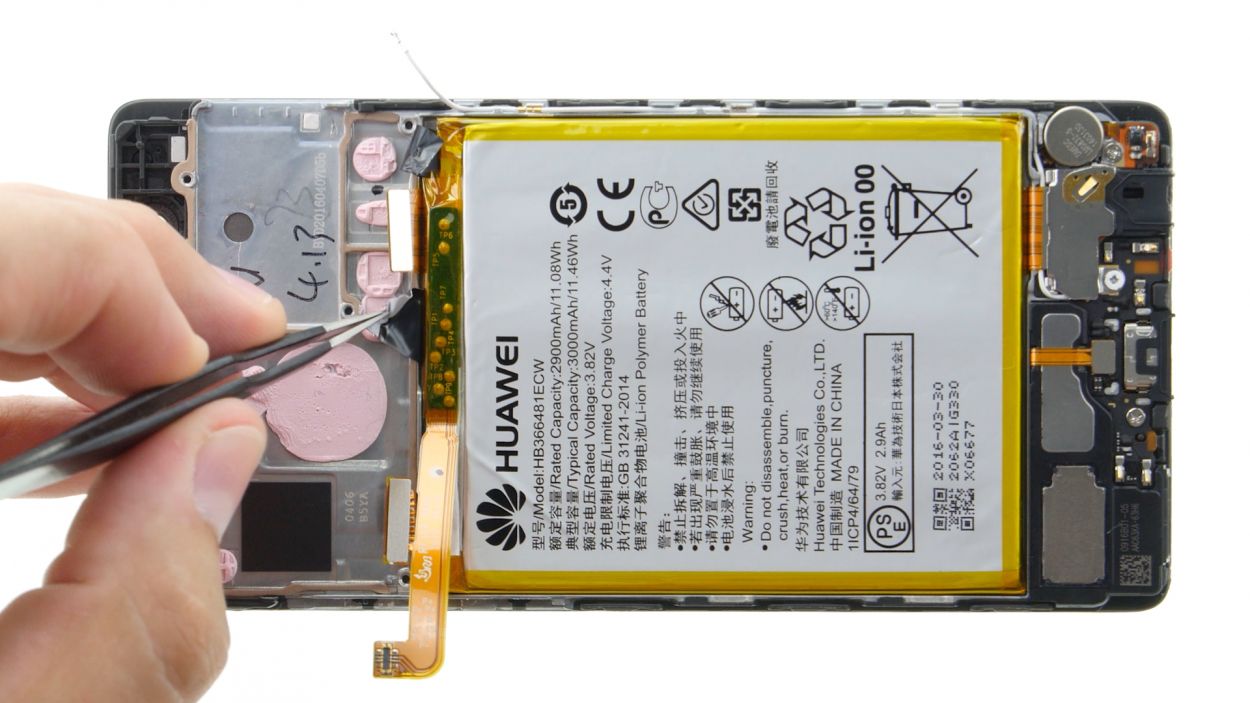
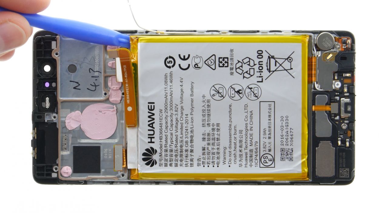
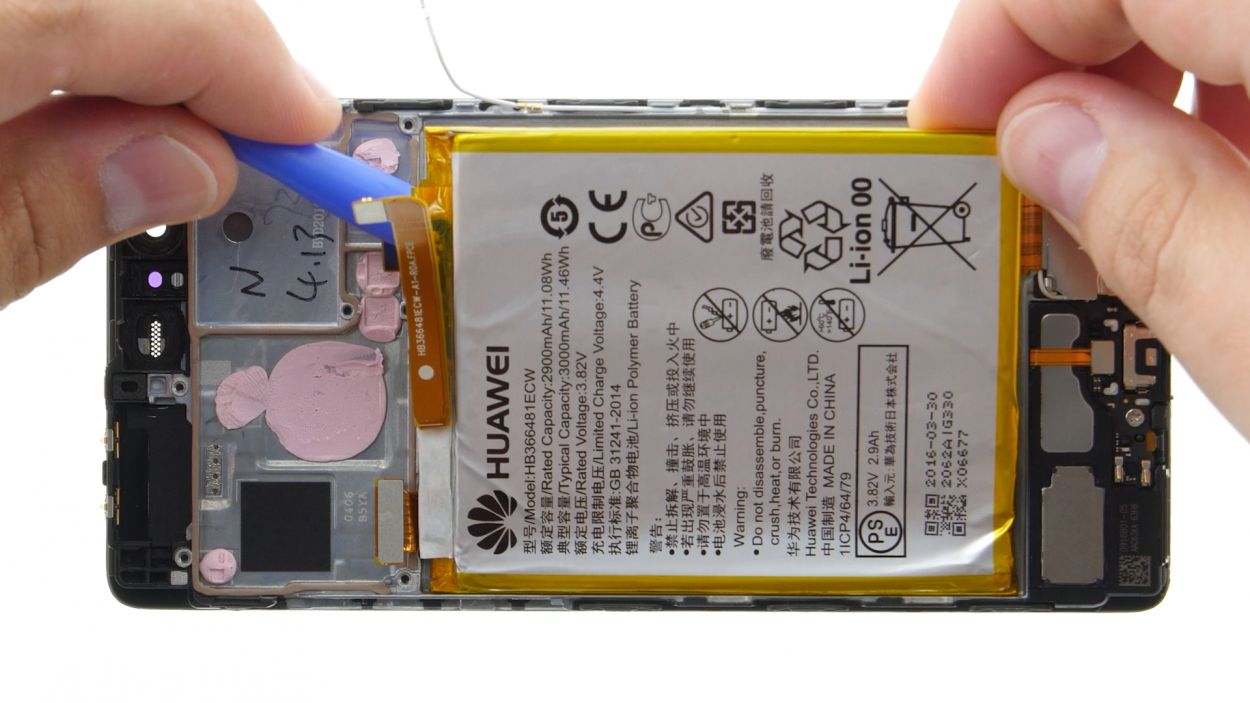
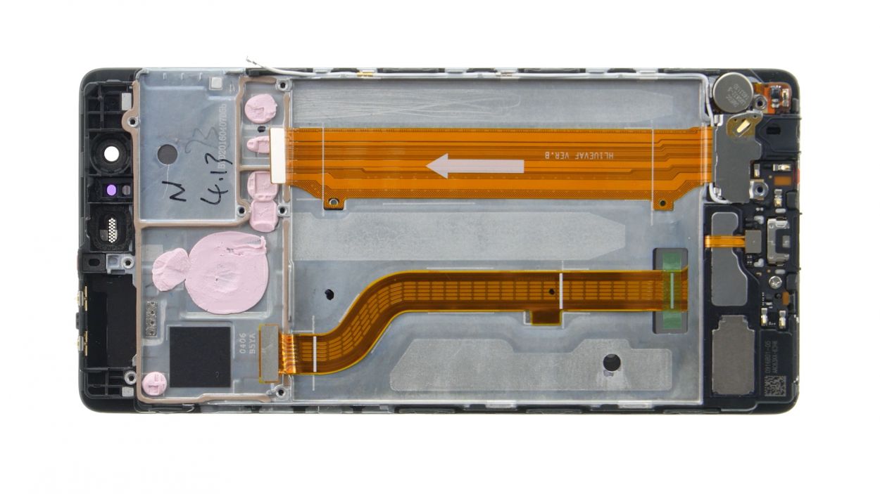
Klebestreifen / Adhesive Stripes
– Flip the battery connection cable on its back to reveal the magic sticky strips underneath!
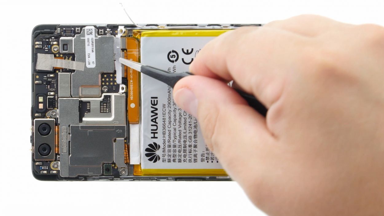
– The battery’s snug as a bug with glue at three spots (we’ve marked these in green for you). Start by freeing the top two strips—just grab the little tails peeping out.
– Peel the ends of these sticky strips off the battery, set yourself up for a smooth strip-pulling experience.
– Now, go for the grand strip pull! Tackle each strip one by one, keeping them as flat as possible and maintain a nice, even pace—steady hands win this race, and we don’t want any strip snaps!
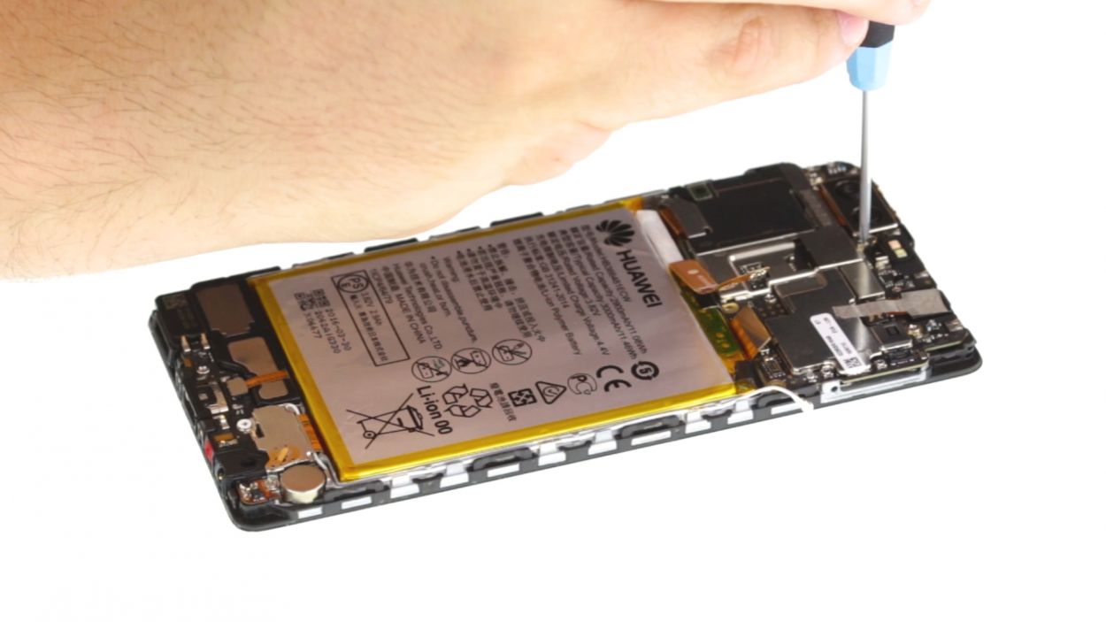
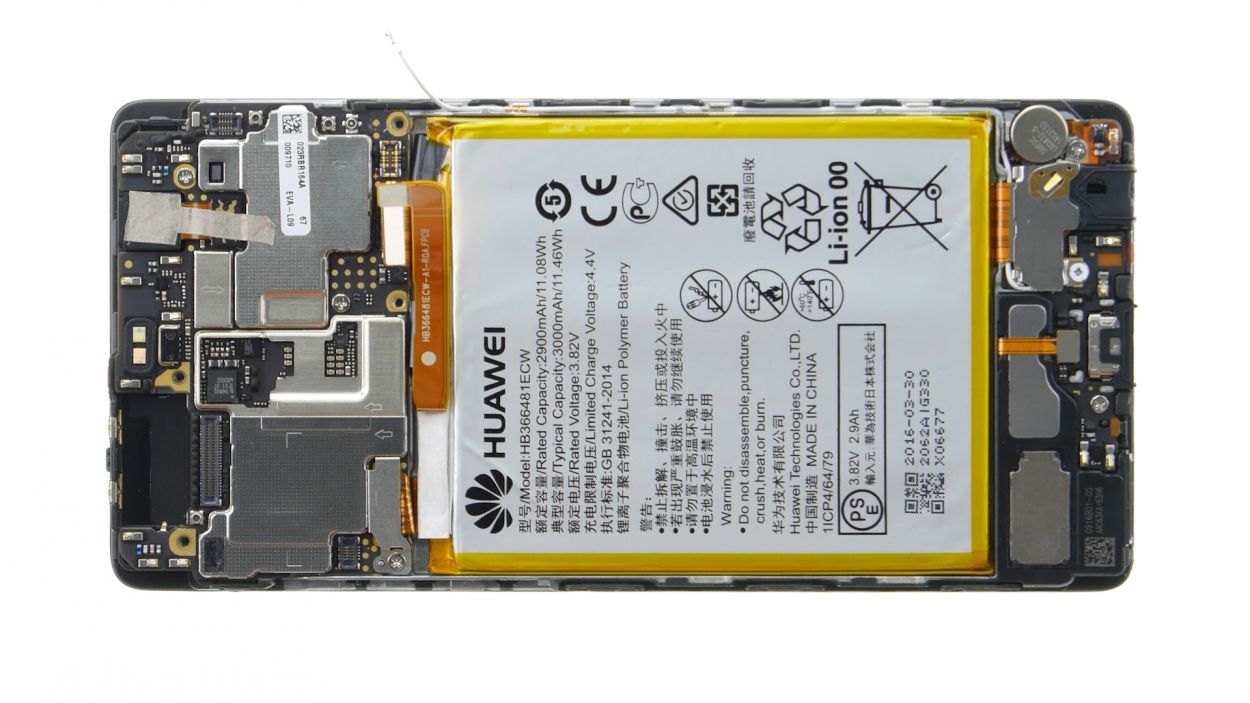
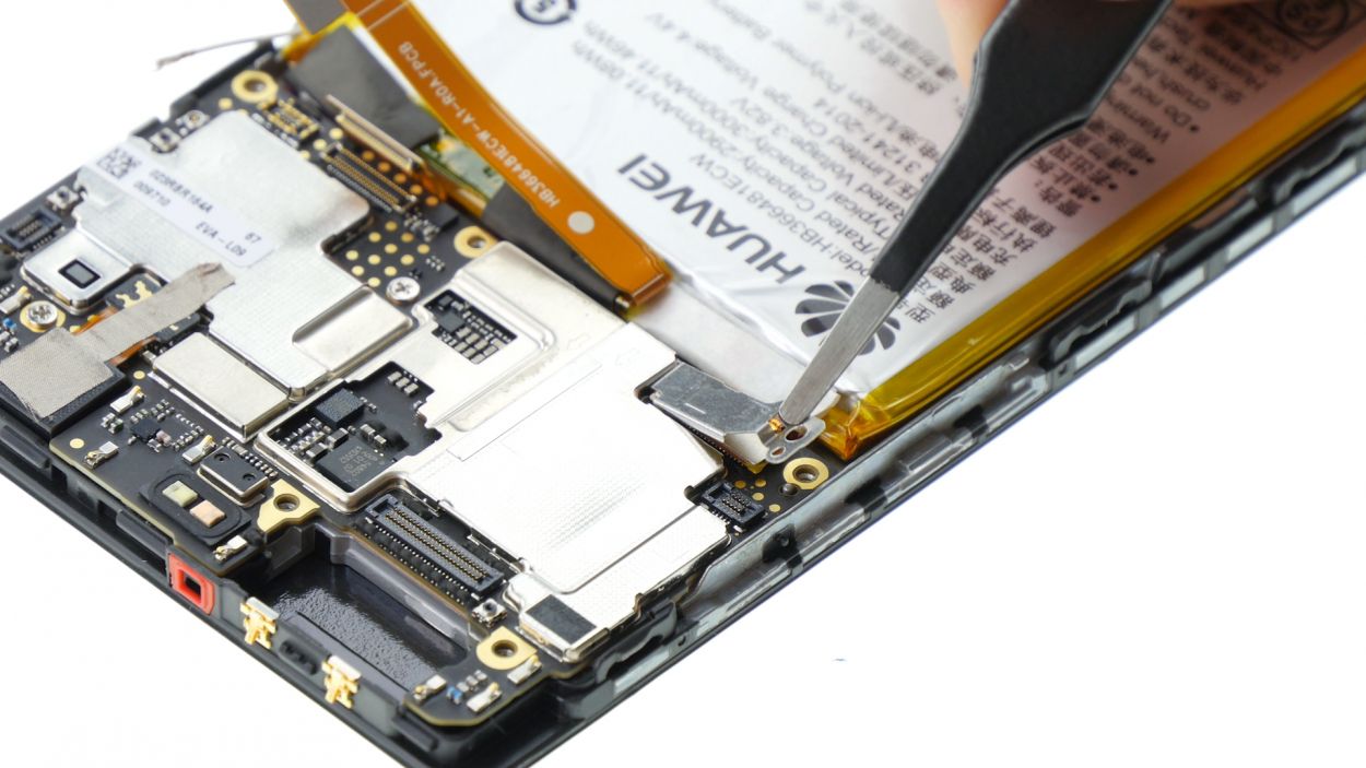
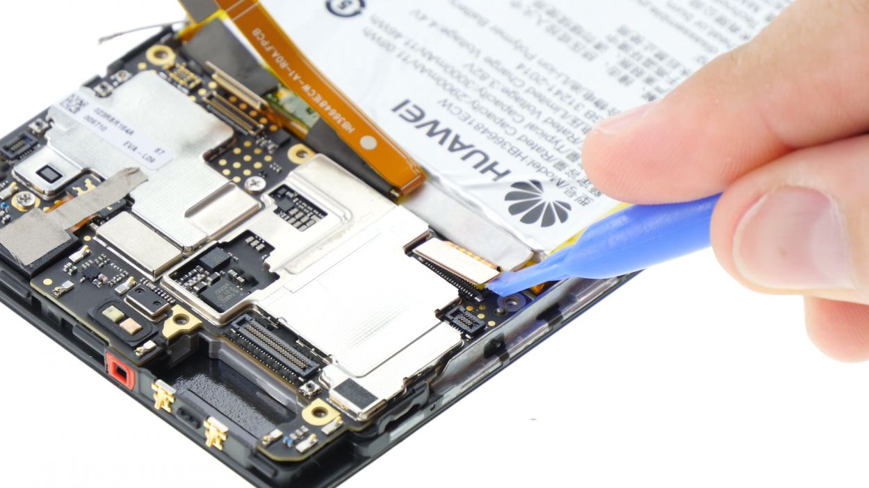
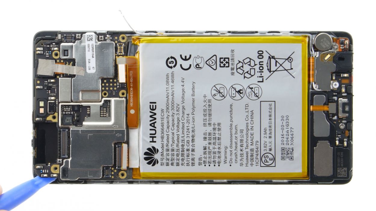
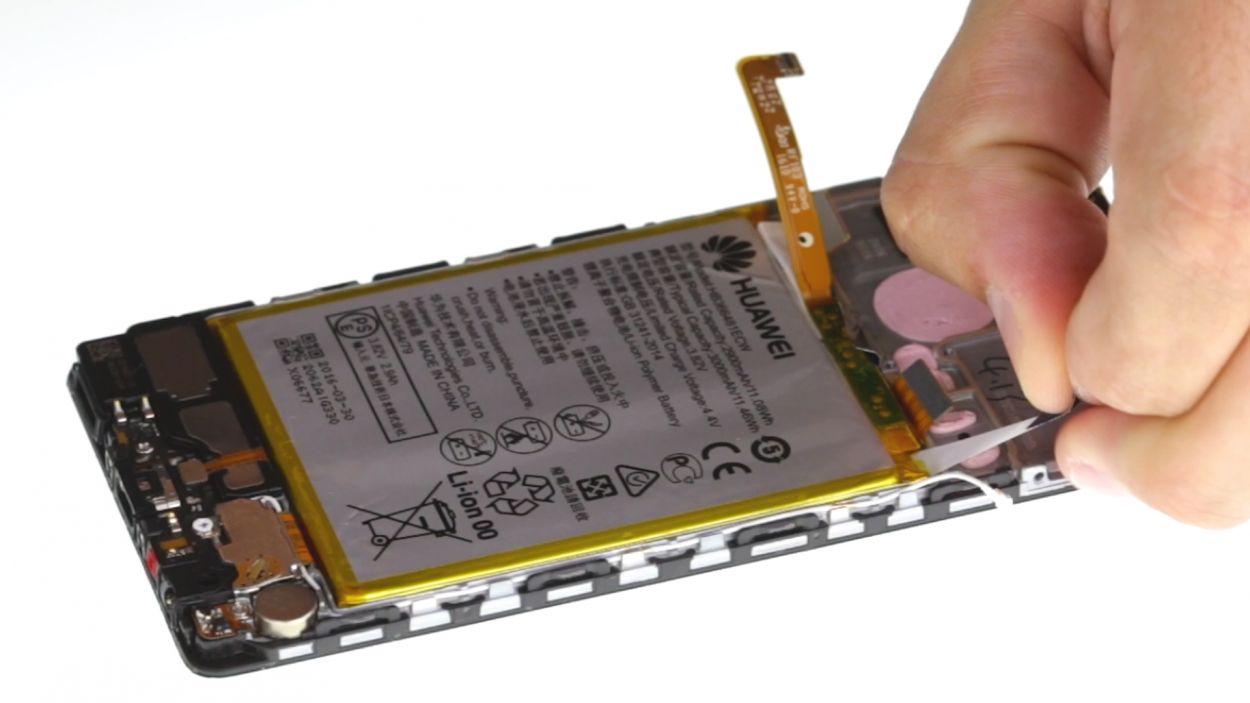
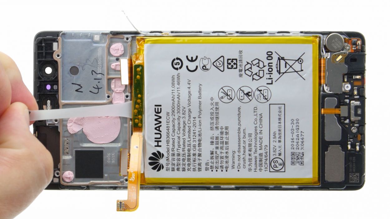
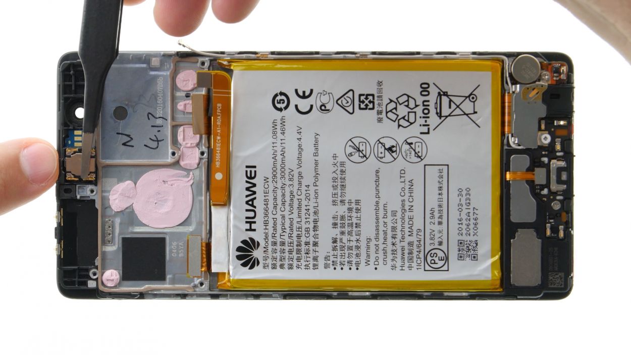
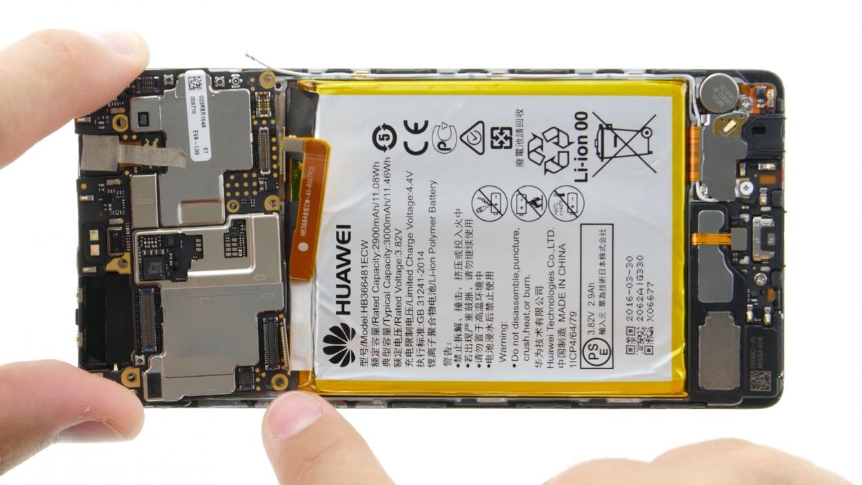
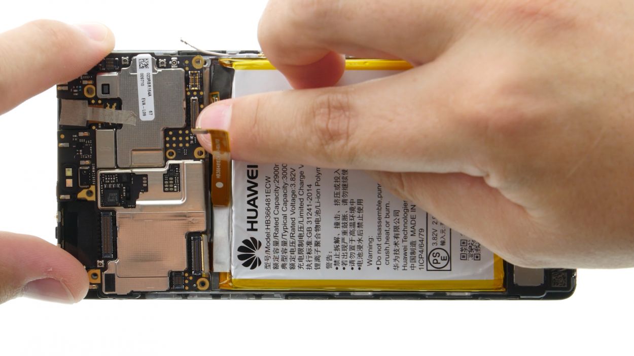
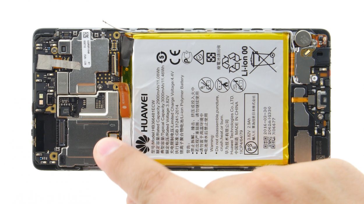
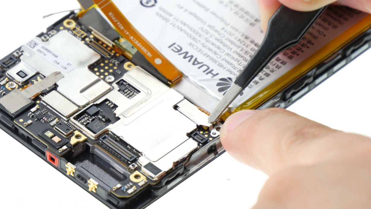
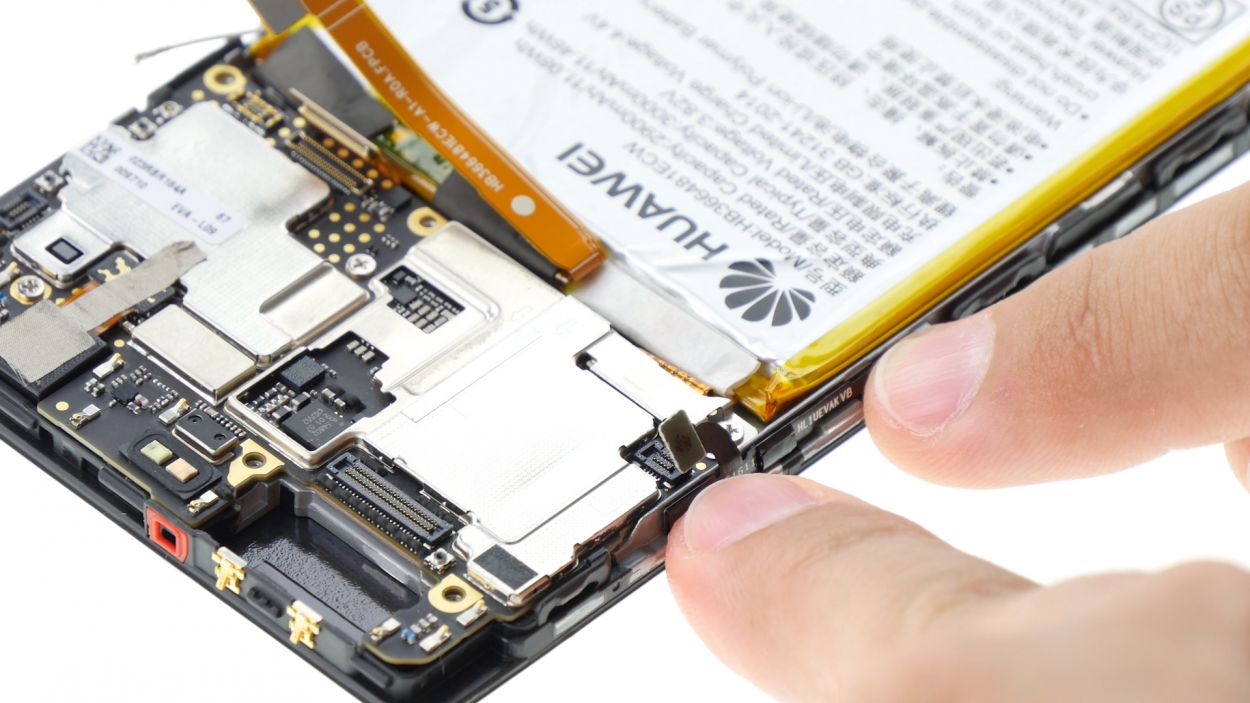
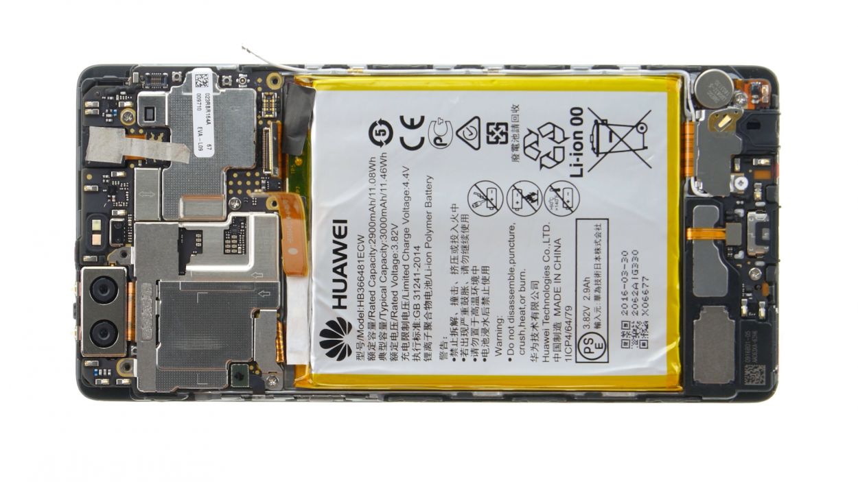
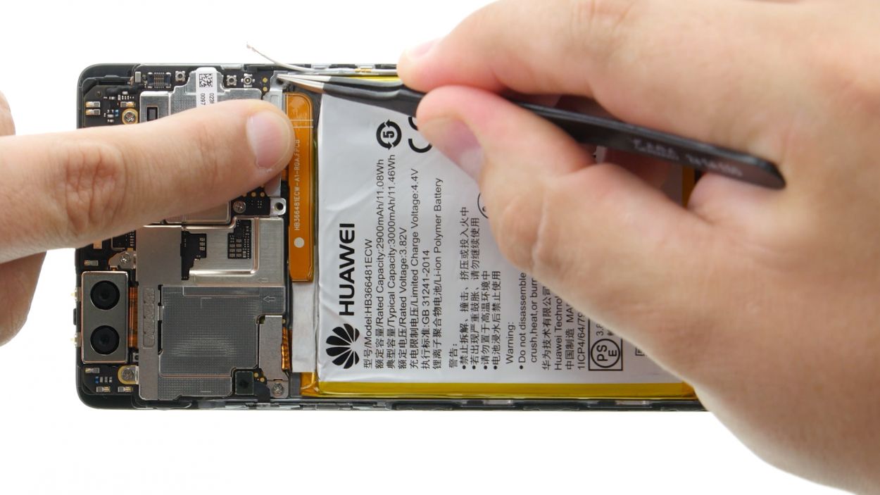
Step 13
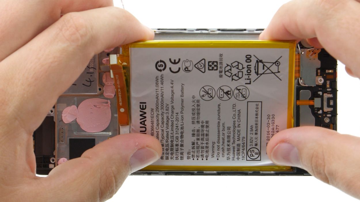
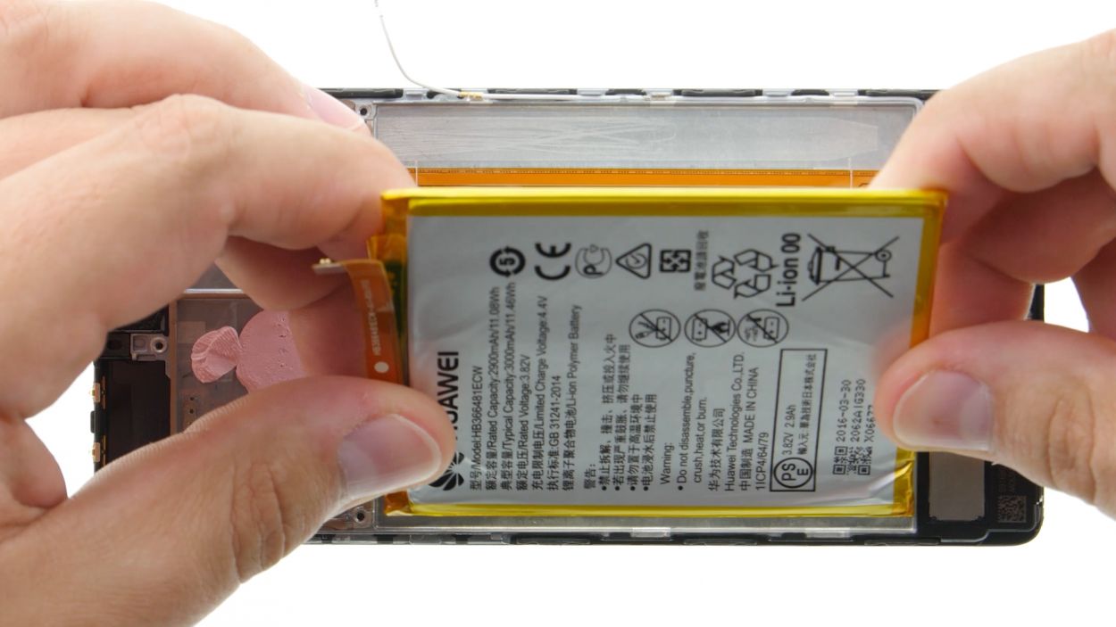
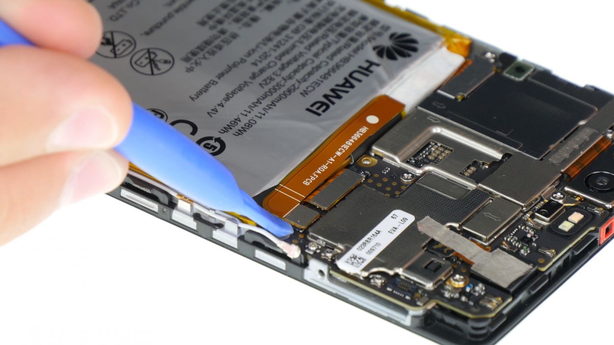
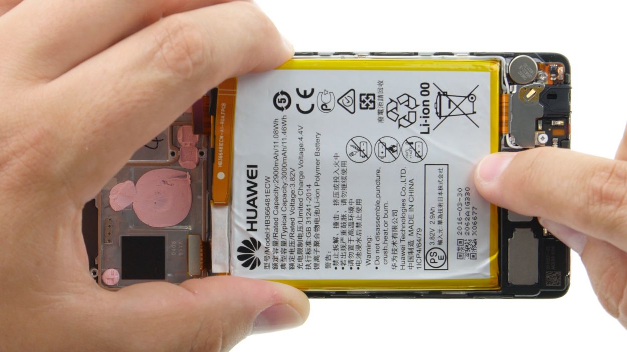
All right, take extra care here! Whip out your flattest, most harmless tool—think the dull end of a metal spatula—and gently coax that battery out without any drama.
– The lower edge of the battery is still holding on tight! Gently coax it up with your trusty steel spatula, then slide in the spudger for some extra help.
– Now, with the spudger in hand, keep prying it loose and work on that stubborn glue. You’ve got this!
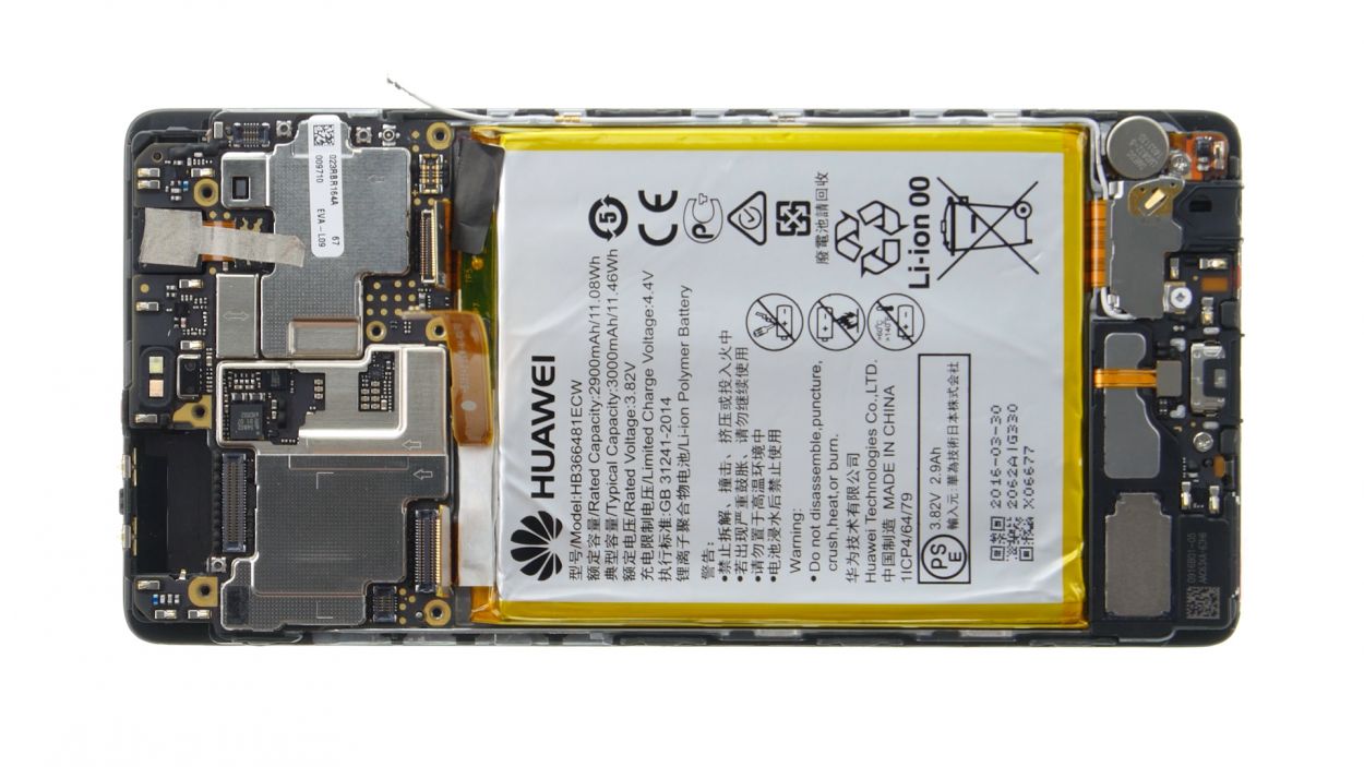
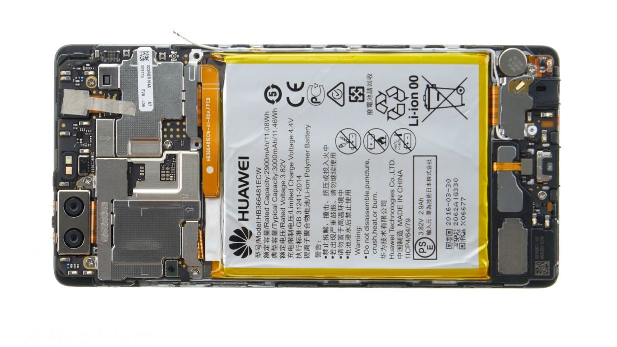
– Time to say goodbye to the battery! Remove it with confidence.
Step 14
2 × 2,5 mm PH00 Phillips-Schrauben
– First up, there’s a plate keeping that headphone jack snug as a bug. Let’s unscrew those two screws holding it down.
– Once those screws are out, lift off the plate and reveal the hidden connection underneath.
– Now, it’s time to gently disconnect the jack’s contact from its little board. Be careful, we want to keep things tidy!
– Finally, go ahead and remove the headphone jack. You’re almost there!
Step 15
1 × 2,5 mm PH00 Phillips-Schraube
Antenna Cable
Speaker Connector
Flexible Flat Cable
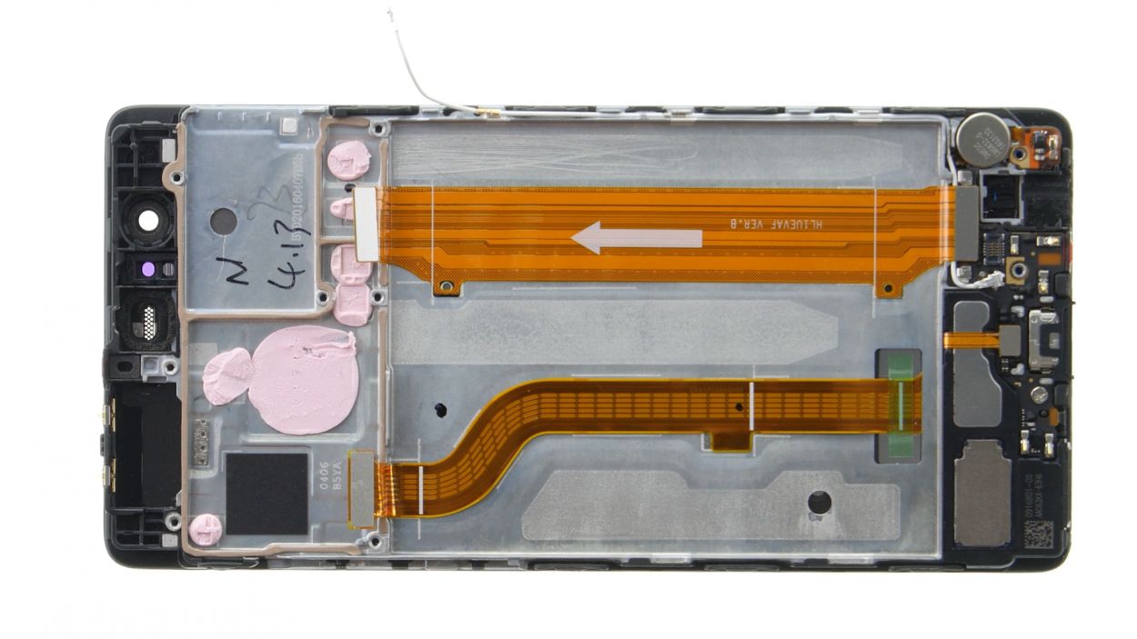
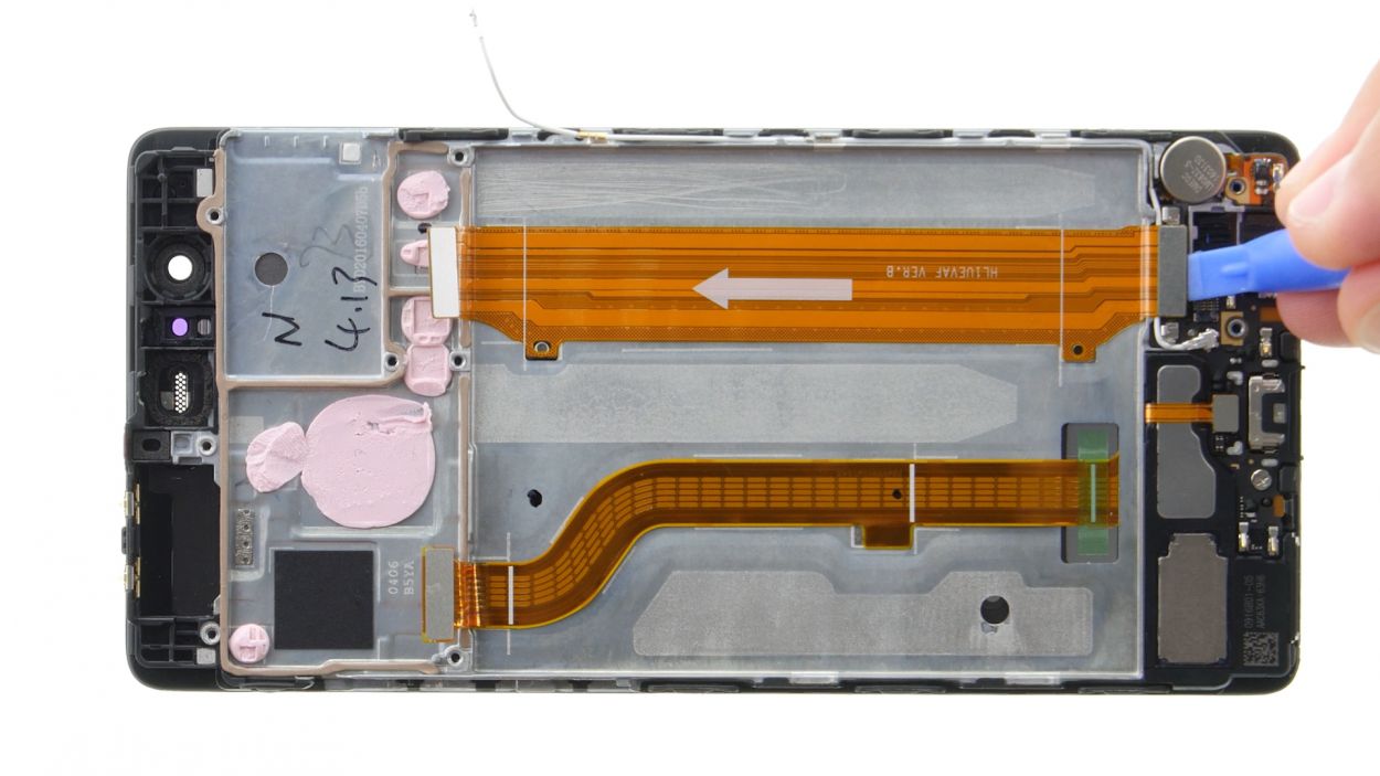
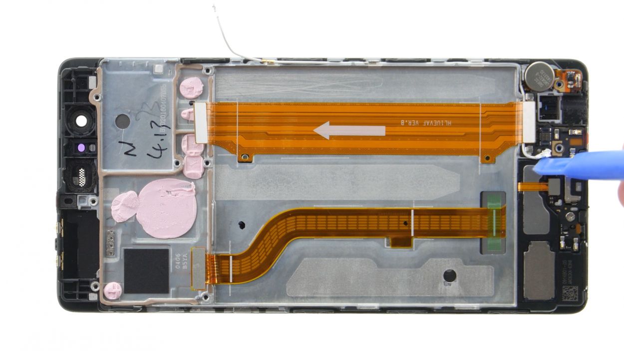
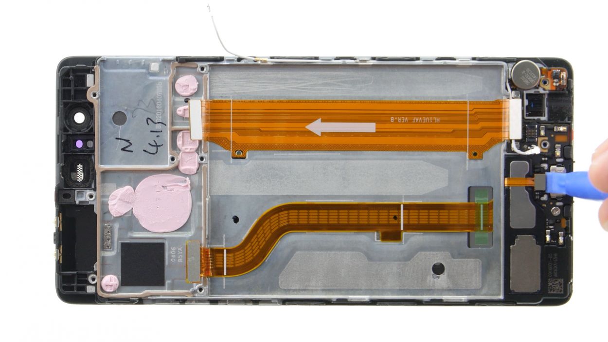
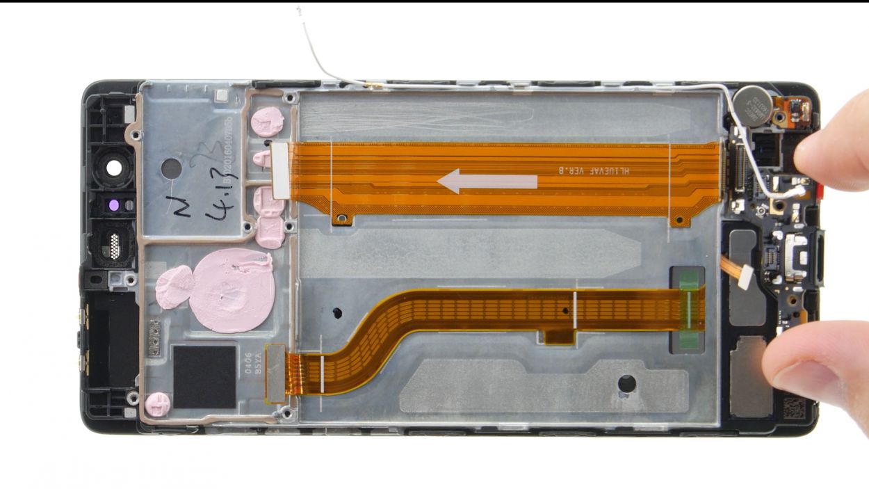
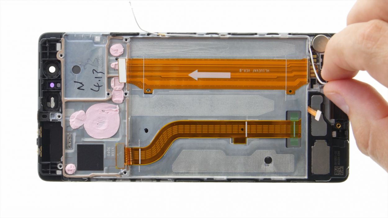
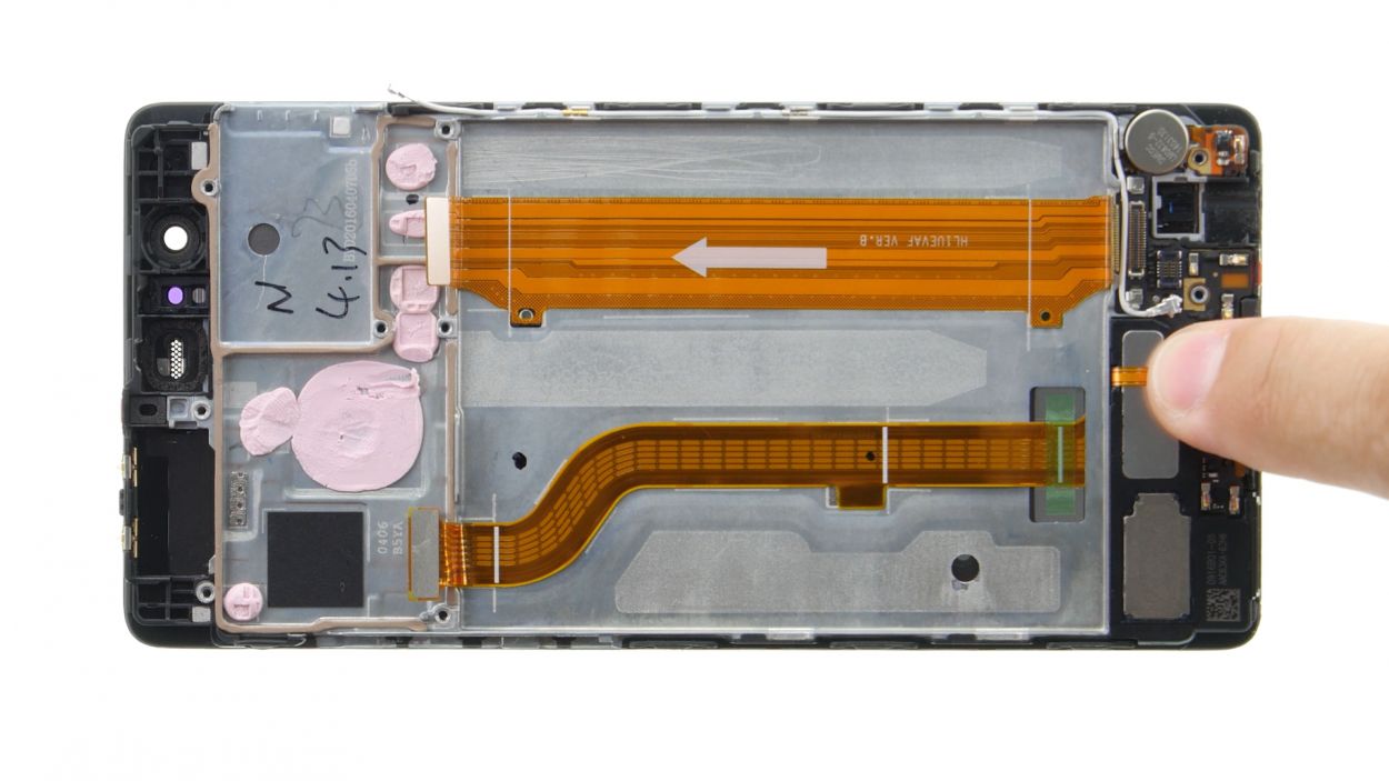
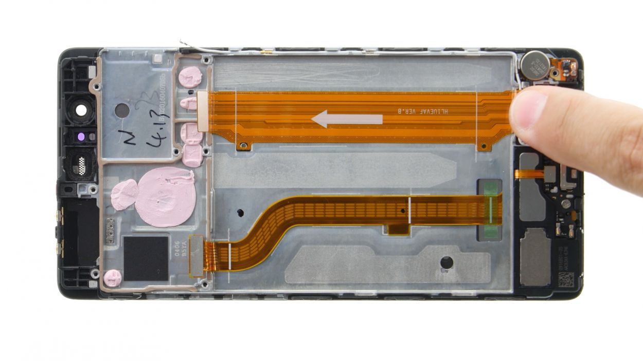
– Grab your trusty spudger and gently detach the wide flexible flat cable from the little board. You’ve got this!
– Next up, let’s disconnect that white antenna cable. Just a little tug, and it’s free!
– Now, it’s time to unplug the speaker contact from the board. Easy peasy!
– Unscrew the screw that’s holding the board in place. Just a twist and it’s gone!
– Finally, go ahead and lift out the board. You’re making great progress!
Step 16
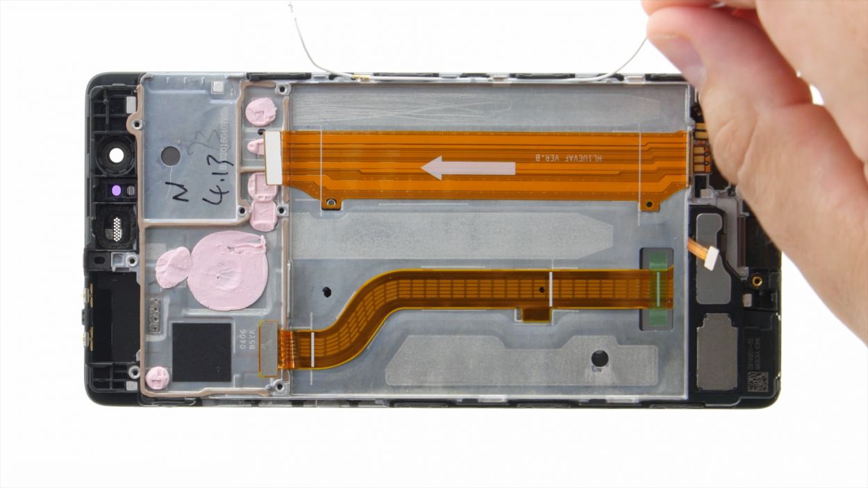
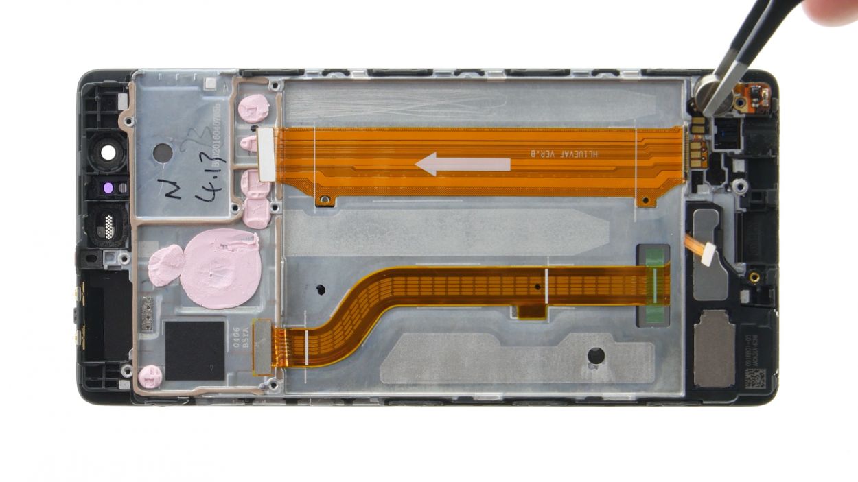
– Gently wiggle the antenna cable free from its guide.
Step 17
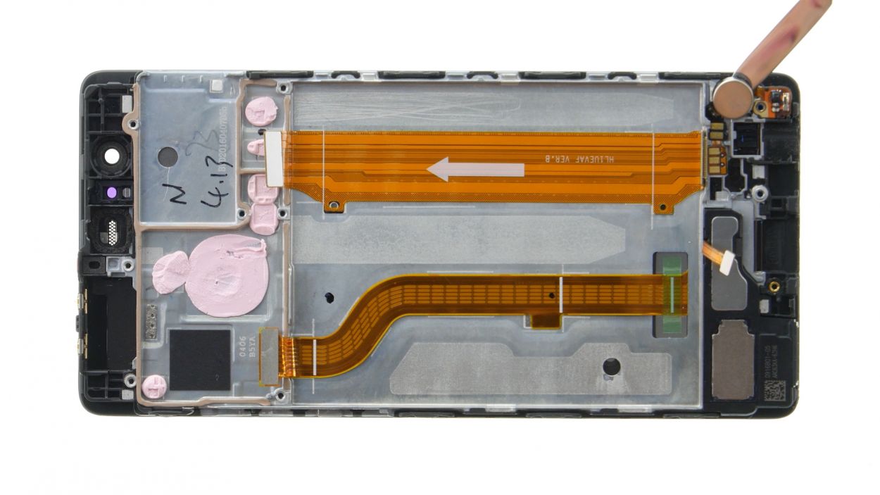
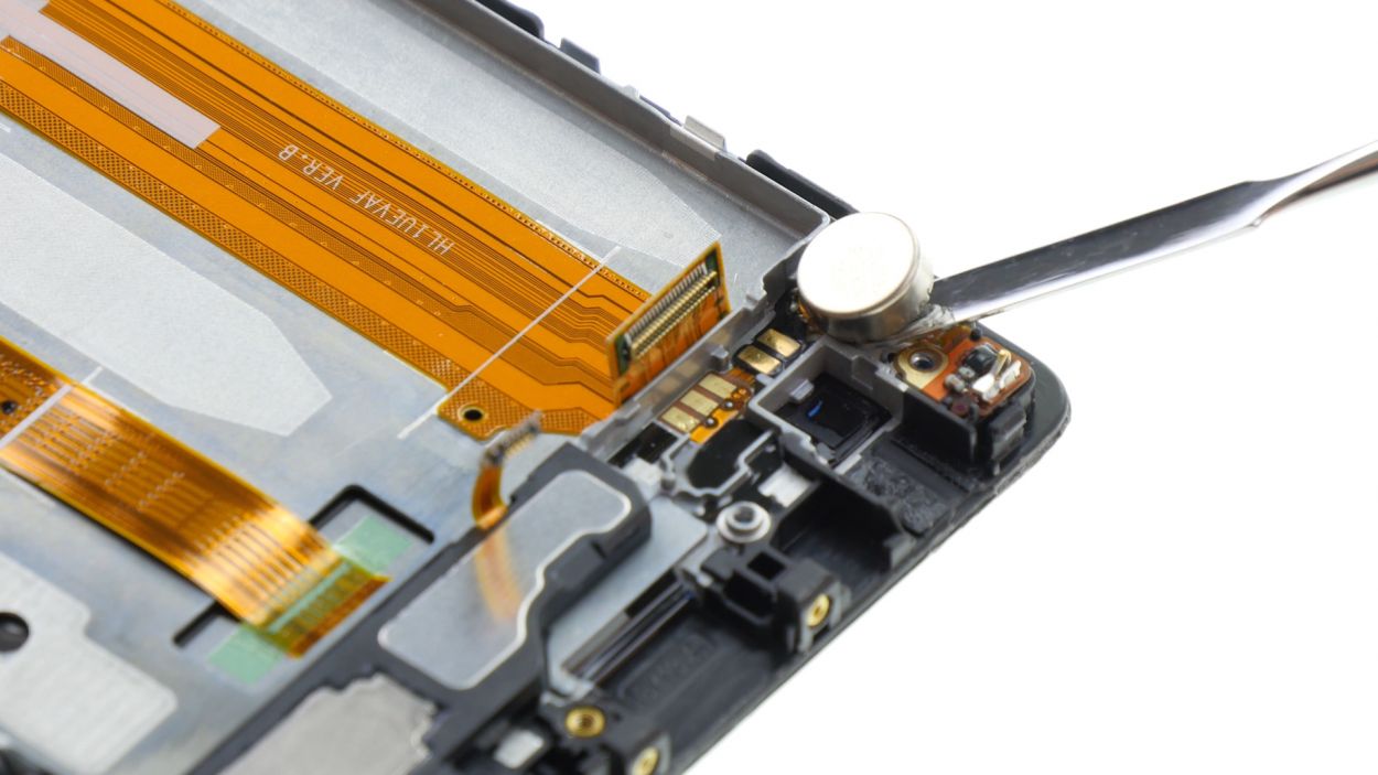
– The vibrator motor is stuck to the enclosure like a sticker. Grab your trusty steel spatula and gently tease that motor away. Slide the spatula in between the enclosure and the motor’s connections with care.
– Once you’ve coaxed it free, go ahead and lift it out!
Step 18
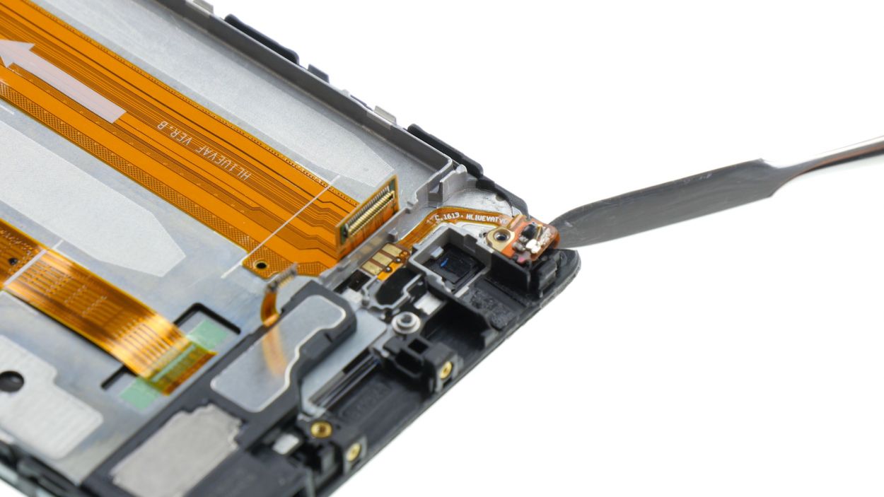
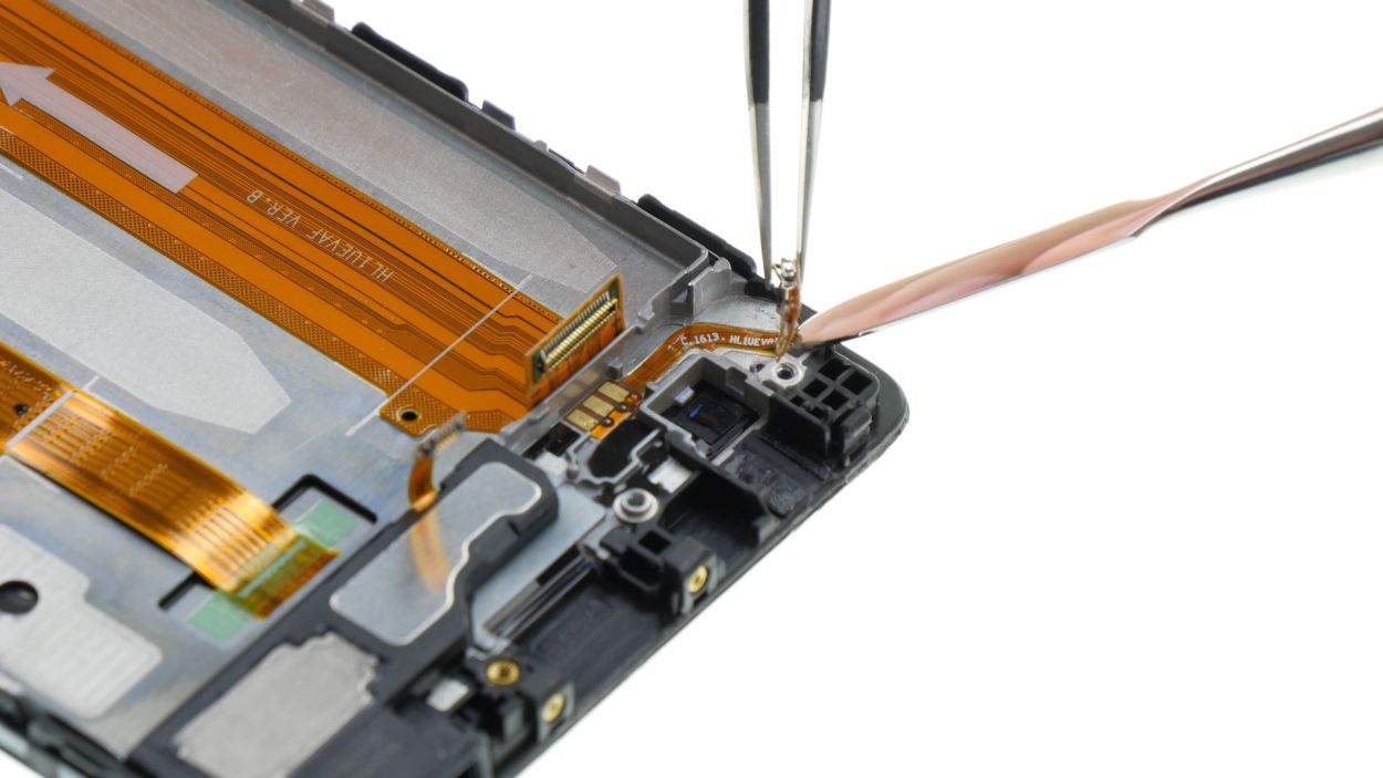
– That teeny antenna’s glued down! Gently slide your steel spatula between the antenna and the enclosure to give it the slip.
– If you need a little extra help, carefully lift the antenna with your tweezers.
– And there you have it – antenna freedom!
Step 19
– The speaker’s got a little glue action keeping it snug with the enclosure. Grab your trusty spatula and gently pry it loose, just like peeling a sticker off a surface.
– Say goodbye to the speaker—it’s time for a removal!
– Now, that flexible flat cable is also a bit sticky with glue. Slip your steel spatula between the cable and the enclosure, and nudge it away like you’re freeing a stuck piece of gum.
Step 21
– Gently slide that wide flexible flat cable back into its cozy spot and give it a little press until it hugs the enclosure securely.
– Nestle the speaker back into its home in the lower left corner of the enclosure and press down gently to help it stick like a champ.
Step 22

– Slide that antenna back into the enclosure, using those handy little tabs to get it just right!
– Give the antenna a gentle press to make sure it sticks around for the long haul.
Step 23
– Nestle the motor in the cozy little nook on the lower right edge and give it a gentle press to make it stick like a champ!
Step 24

1 × 2,5 mm PH00 Phillips-Schraube
– Nestle the board snugly into its cozy enclosure.
– Secure that board with a trusty screw for a nice, tight fit.
Step 25
Antenna Cable
– Time to connect that white antenna cable! Piece of cake.
– Now, gently tuck the antenna cable back into its home at the enclosure’s edge. Almost there!
Step 26

Earpiece Connector
Flexible Flat Cable Connector
Speaker Connector
2 × 2,5 mm PH00 Phillips-Schrauben
– First up, let’s connect that speaker to the board—it’s time for a little reunion!
– Gently press the wide flexible flat cable’s contact into the socket like you’re tucking it in for a cozy nap.
– Next, slide the headphone jack into its comfy spot in the enclosure. It’s like finding the perfect couch!
– Reconnect the jack to the little board—it’s a team effort!
– Now, let’s secure that jack by putting the plate back on. Safety first!
– Finally, attach the plate to the jack with those two screws. Tighten them up, and you’re all set!
Step 27
Before you pop that new battery in, double-check for adhesive+strips+P9&crid=1TJIMMAJSUJUZ&sprefix=repair+tools%2Caps%2C165&linkCode=ll2&tag=salvationrepa-20&linkId=c486487cf454ce8edd6f5beefab4110f&language=en_US&ref_=as_li_ss_tl’>adhesive strips! If your battery is feeling a little loosey-goosey, it might just bounce around inside the enclosure. And trust us, that’s a recipe for disaster! Keep it snug and safe to avoid any mishaps with your precious device.
Step 28
– Nestle the proximity sensor into its little home and give it a gentle but firm press so the glue can do its magic.
Step 29
– Nestle that earpiece right into its cozy little spot.
– Give it a gentle press to help the glue work its magic and create a solid seal.
Step 30
2 × 2,5 mm PH00 Phillips-Schrauben
– Gently place the board back into its cozy enclosure. Give it a little press until you hear that satisfying click.
– Look for the tiny holes – one in the upper right and another in the lower left of the board. Make sure the tabs on the enclosure snugly fit into those holes. This makes positioning the board a breeze!
– Grab those two screws and secure the board to the enclosure like a pro.
Step 31
Display Connector
1 × 2,5 mm PH00 Phillips-Schraube
– First, let’s connect that display contact to the motherboard—like putting together your favorite puzzle piece!
– Next up, place the plate back over the contact, snug it in nicely.
– Finally, grab that screw and secure the plate to the motherboard with a twist—you’re doing great!
Step 32
– Pop those control buttons back onto the frame! Those little tabs on the frame are your best friends for perfect placement – just guide them into the cute little holes in the buttons.
– Give those buttons a firm press. We want that glue to get cozy!
– Time to connect the plug contact to the motherboard. Easy peasy, lemon squeezy!
Step 33
2 × 2,5 mm PH00 Phillips-Schrauben
– Slide that camera right into its cozy enclosure!
– Gently connect the contact to the motherboard by pressing the connector snugly into the socket.
– Time to secure everything! Place the plate back on to hold that contact in place.
– Grab those two screws and fasten the plate tight – you’re almost there!
Step 34
2 × 2,5 mm PH00 Phillips-Schrauben
– Gently connect the wide flexible flat cable to the motherboard by pressing it into the socket until you hear that satisfying click.
– Next up, let’s reconnect the battery and get things powered up!
– Carefully place the plate back on to secure those contacts. Remember, it needs to hook onto both the screw holes and the center.
– Now, fasten that plate down with the two screws and make sure everything is snug.
– Lastly, connect the antenna cable to the motherboard and you’re almost there!
Step 35
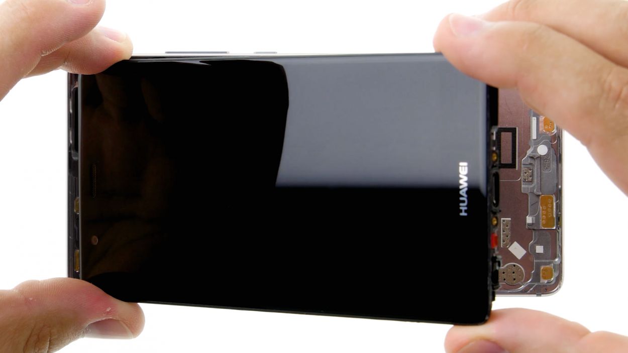
– Start by placing the back cover at the short upper edge of the display and gently connect the fingerprint sensor’s contact. Listen for that satisfying click to know it’s secure!
– Next, close up your device by folding down the back cover and giving the display a little press. You’re almost there!
Step 36
2 × 2,8 mm P1 Pentalob-Schrauben
– Time to wrap it up! Use those two screws at the lower edge of the enclosure to close the device. If you need help, you can always schedule a repair.
Step 37
– Put the SIM tray and any cards back in your device. Make sure the tray is positioned properly.
Step 38
– Power up your device and take a fun little stroll with any app by dragging it all around the screen. Swing it along the edges, then go for a zigzag dance across the display! Remember, the app should always be in sync with your finger. Once you’re done frolicking, give that brightness slider a test drive—slide it all the way down to the minimum and then crank it up to maximum. Have fun with it!