DIY Guide to Replace Earpiece on Huawei P9
Duration: 30 min.
Steps: 19 Steps
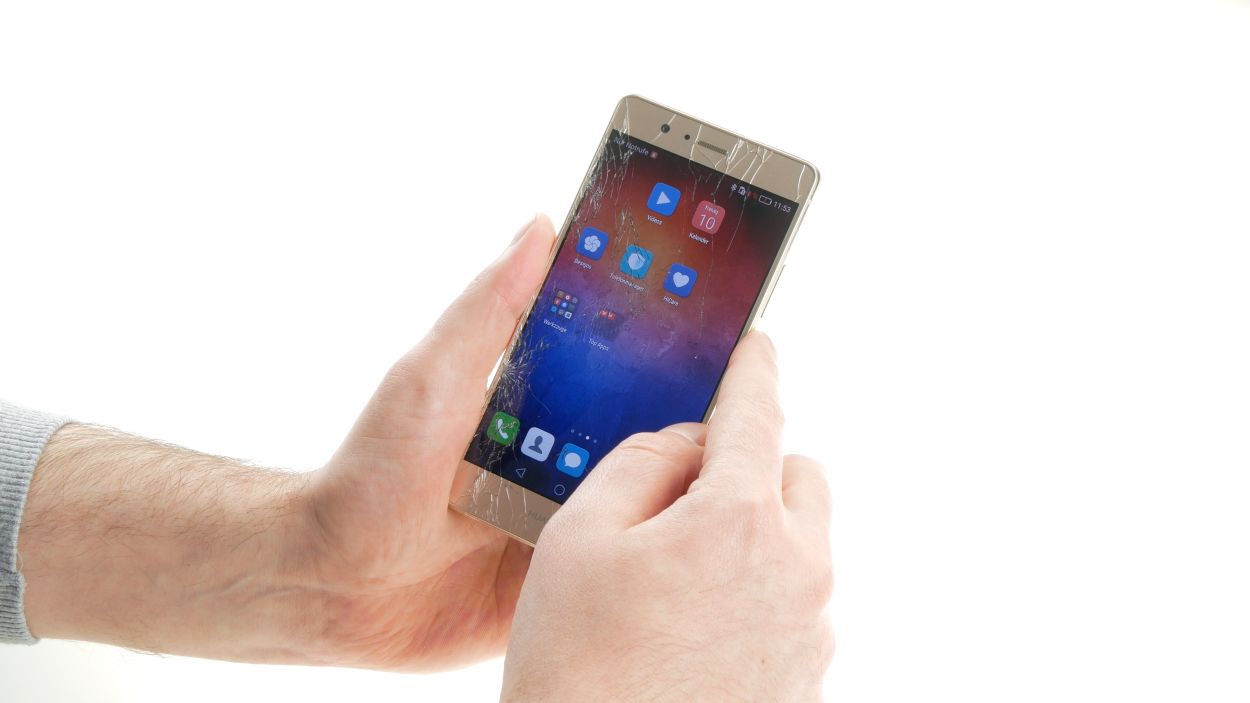
Hey there! Can’t hear your buddy on the phone? Is your P9’s earpiece whispering sweet nothings instead of booming conversations? Or maybe that proximity sensor’s gone AWOL? Don’t sweat it! This guide’s got your back. We’ll walk you through replacing that earpiece like a pro. Get ready to hear crystal-clear calls again! If you need a hand, you can always schedule a repair.
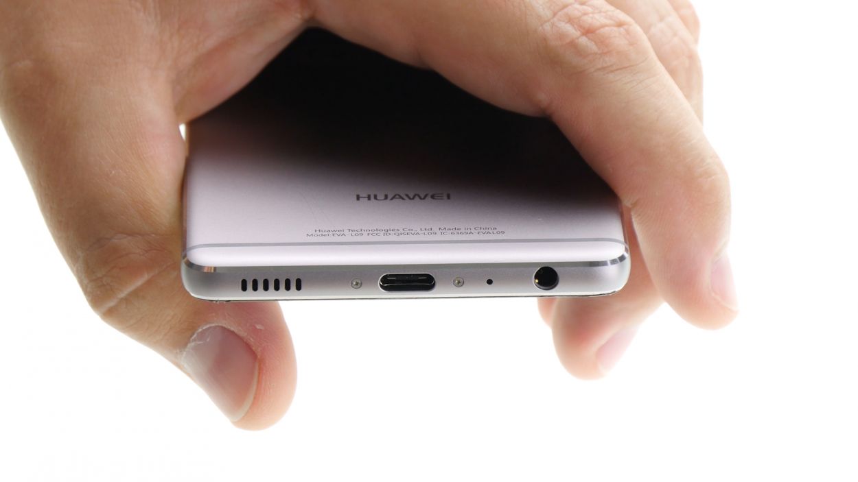
Step 1
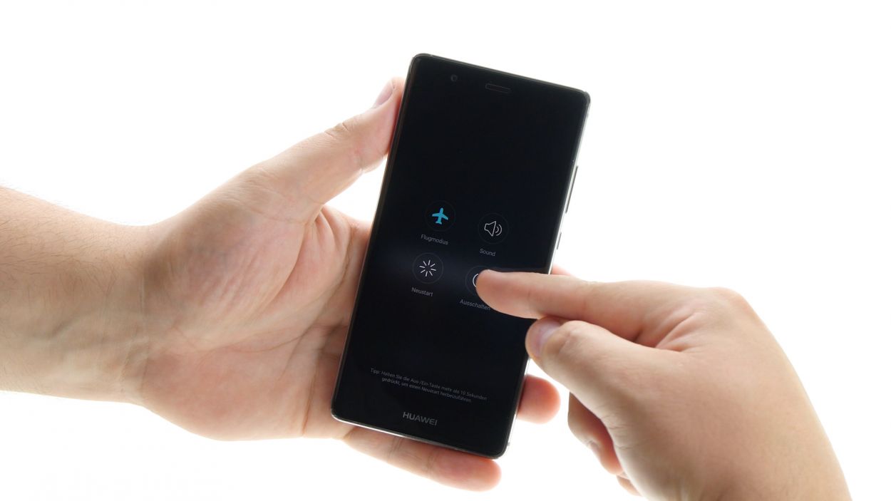
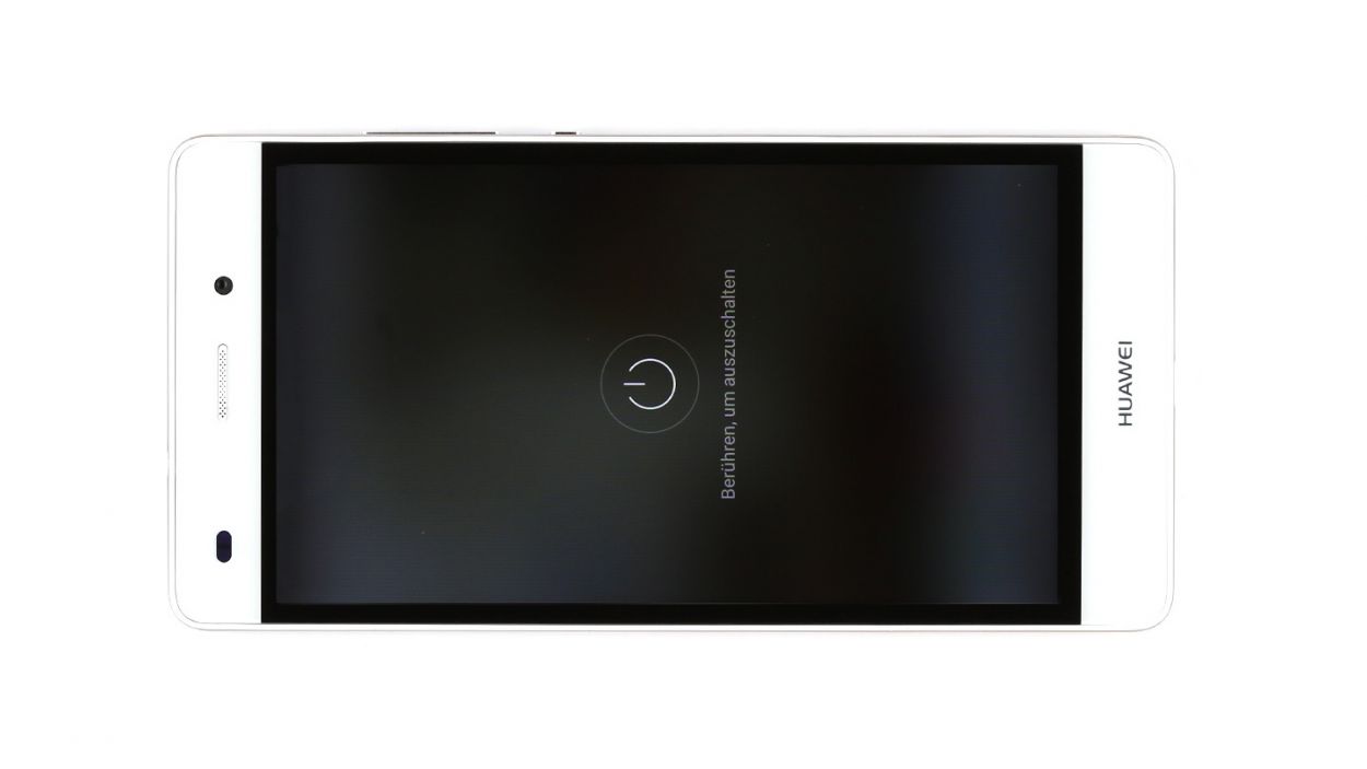
– Turn off your device. Just press and hold that power button until a menu pops up. Choose ‘Power off’ and give it another tap to confirm your decision.
Step 2
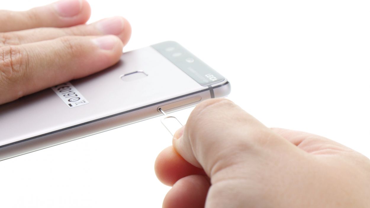
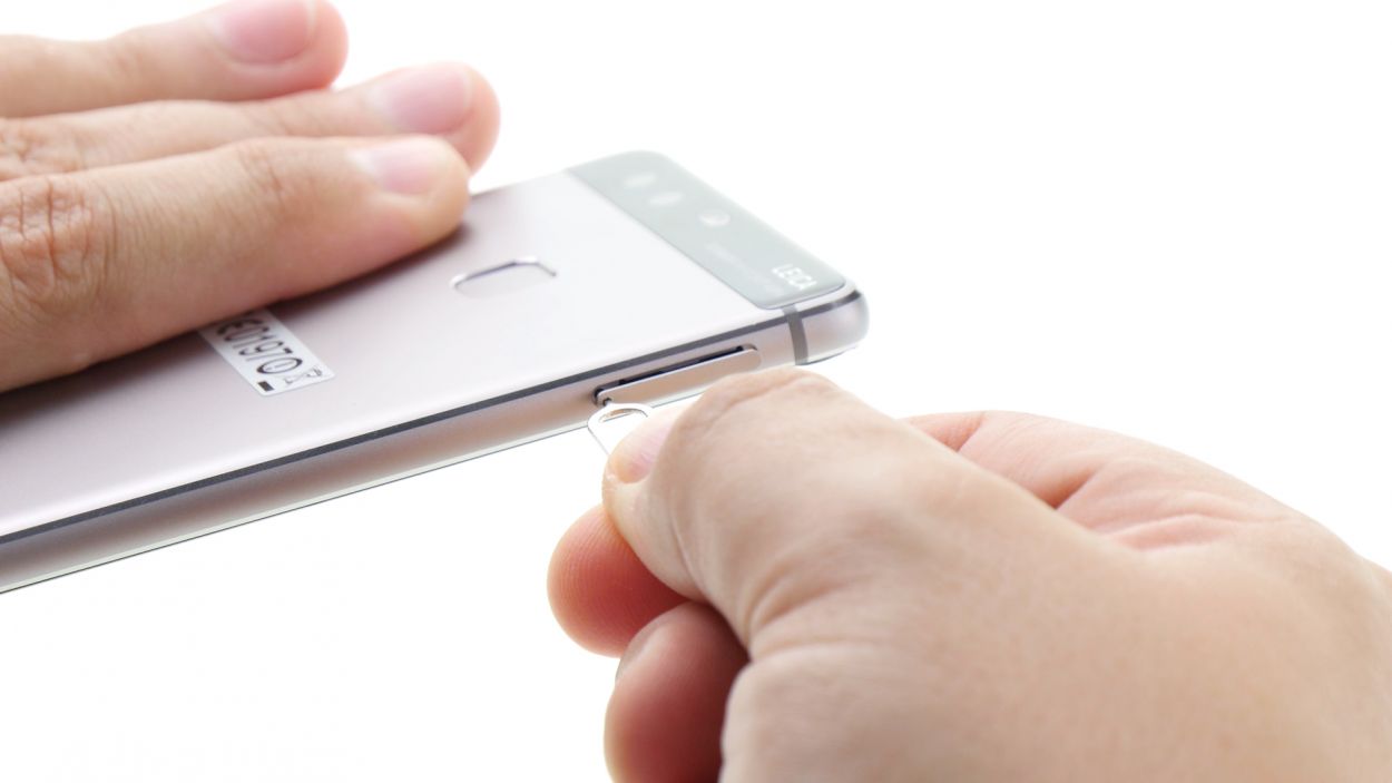
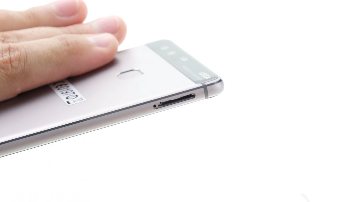
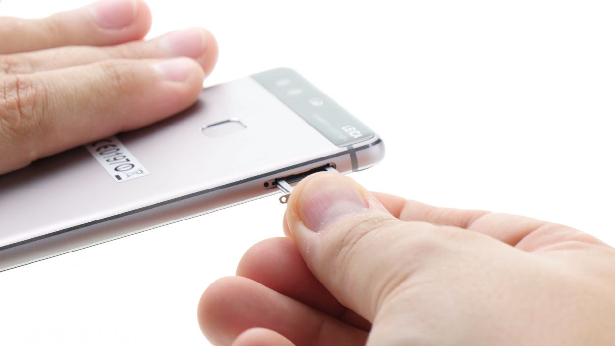
– Pop that SIM tool into the tiny hole on the tray to give it a little nudge and unlock it.
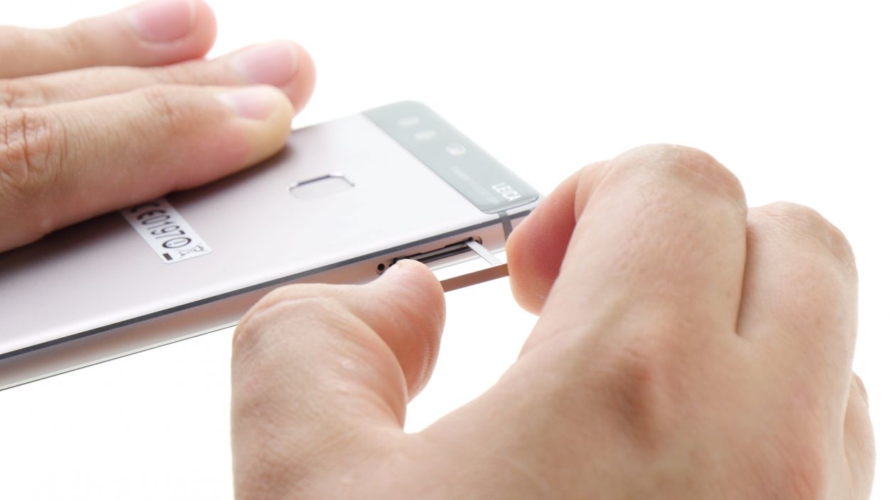
– Gently pull out the SIM tray and, if you’ve got them, take out the SIM and microSD cards too.
Step 3
2 × 2,8 mm P1 Pentalob-Schrauben
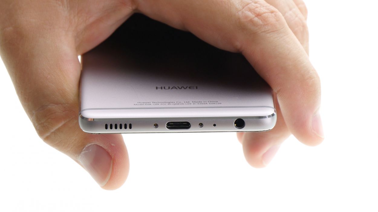
– Carefully twist off those two screws at the bottom of your device that are holding everything together. You’ve got this!
Step 4
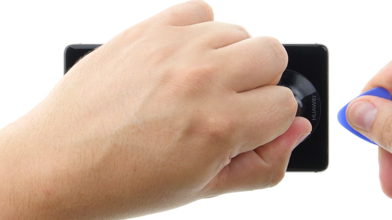
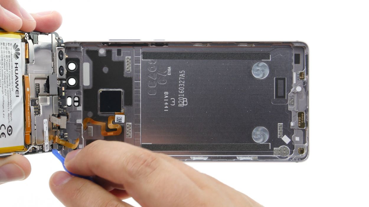
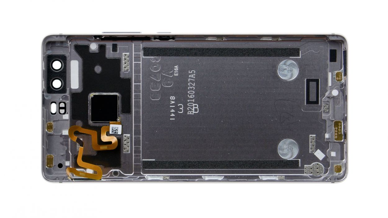
The fingerprint sensor is snugly nestled in the back cover, connected to the motherboard by a flexible flat cable. When you’re gently lifting off the display, keep an eye out for that cable and board—let’s avoid any unintentional damage, shall we?
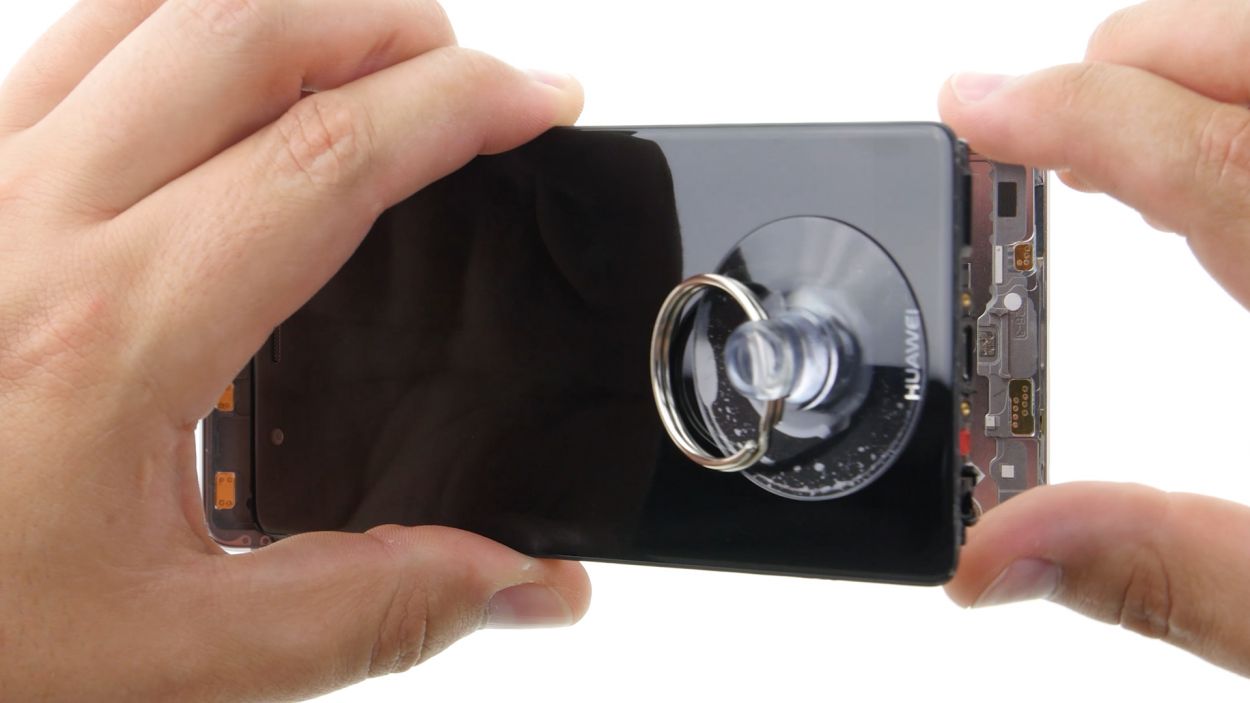
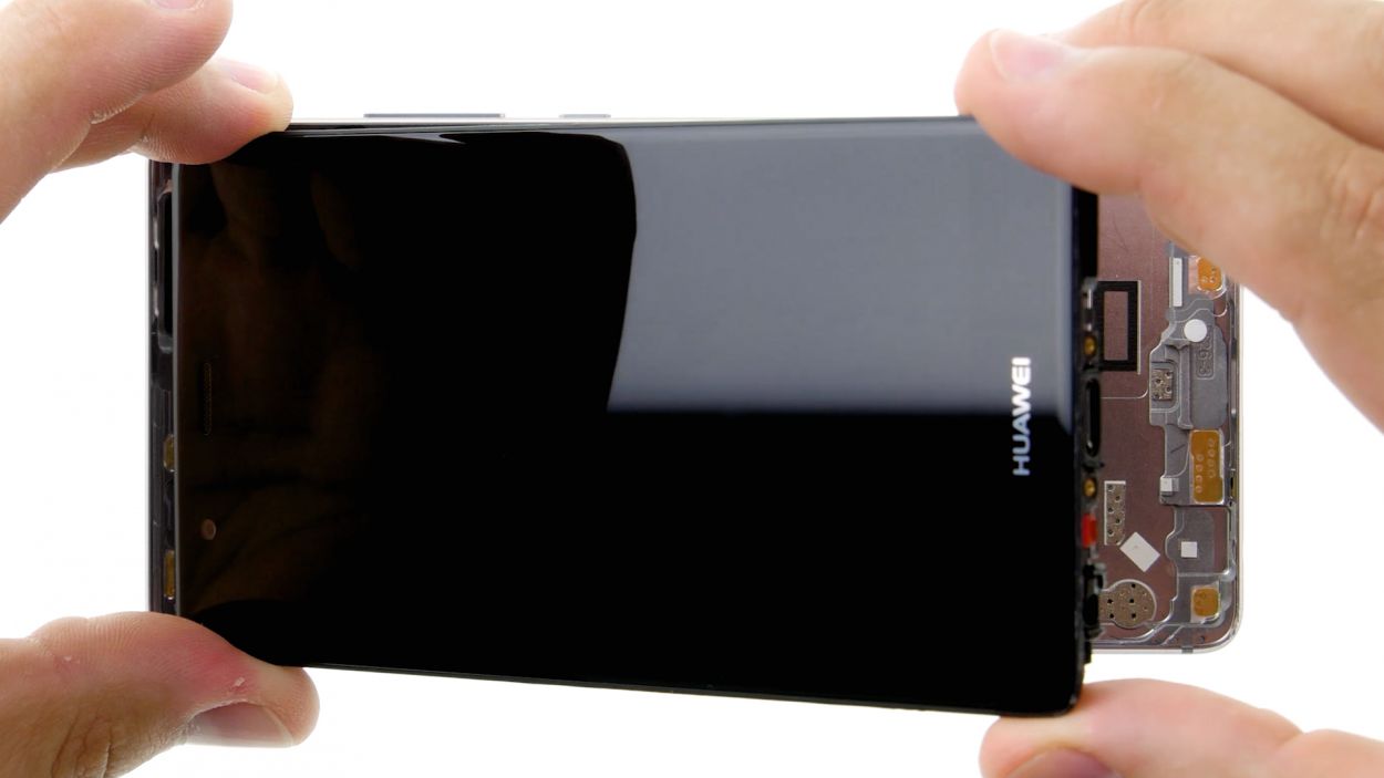
– Place the suction cup as low on the display as you can, like right where it says ‘Huawei.’ If the glass is too shattered for the suction cup to create a seal, just cover the display with some tape.
– While you pull on the suction cup, use the pick to gently push the back cover against the table. Once you see a little gap between the display and the casing, you can carefully slide the pick in.
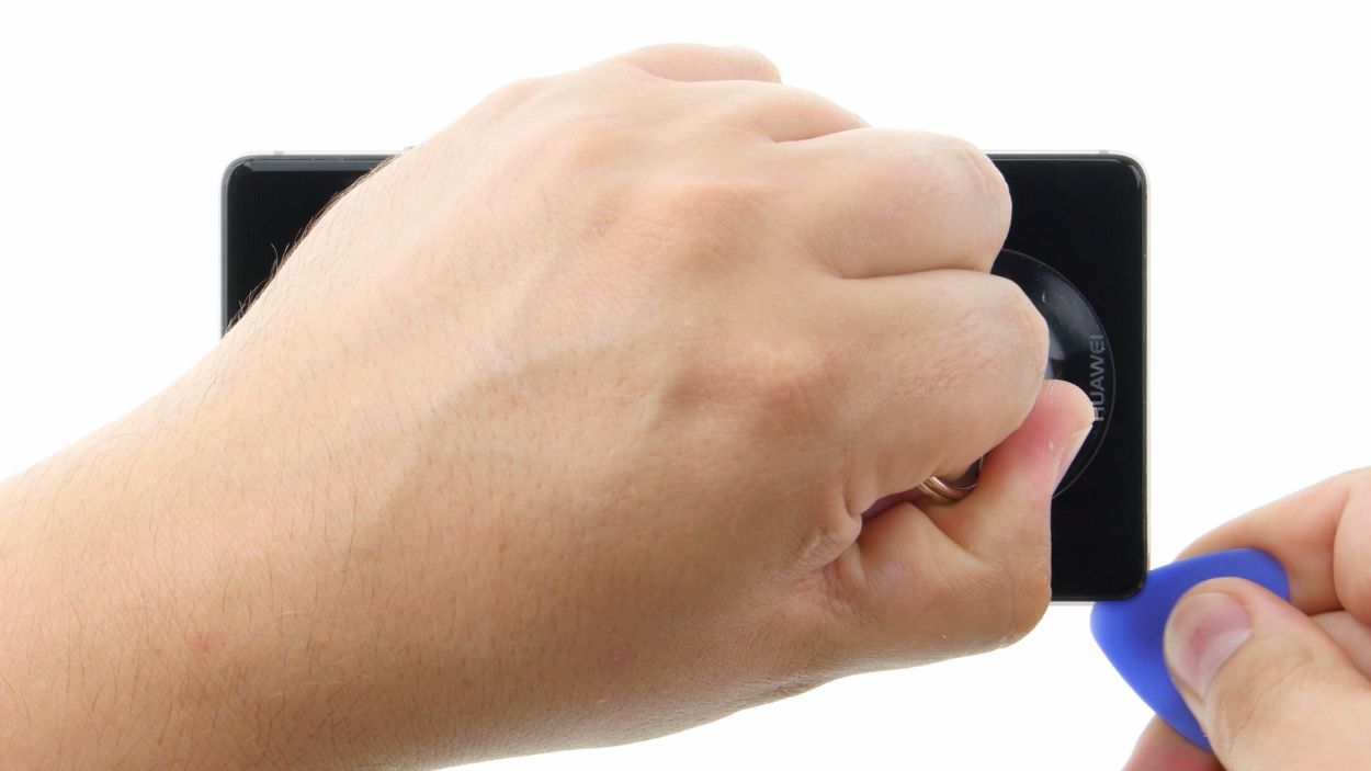
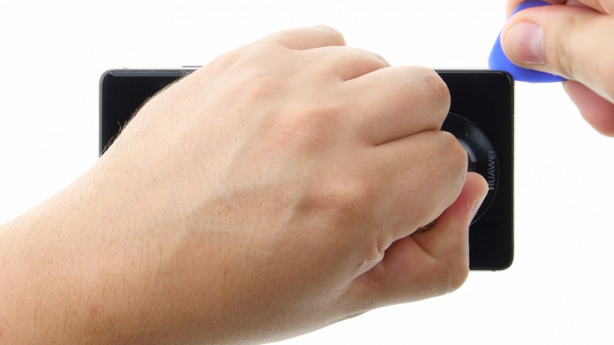
– Now, move the pick along the edges to detach the display from the sides. Keep pulling gently on the suction cup as you go.
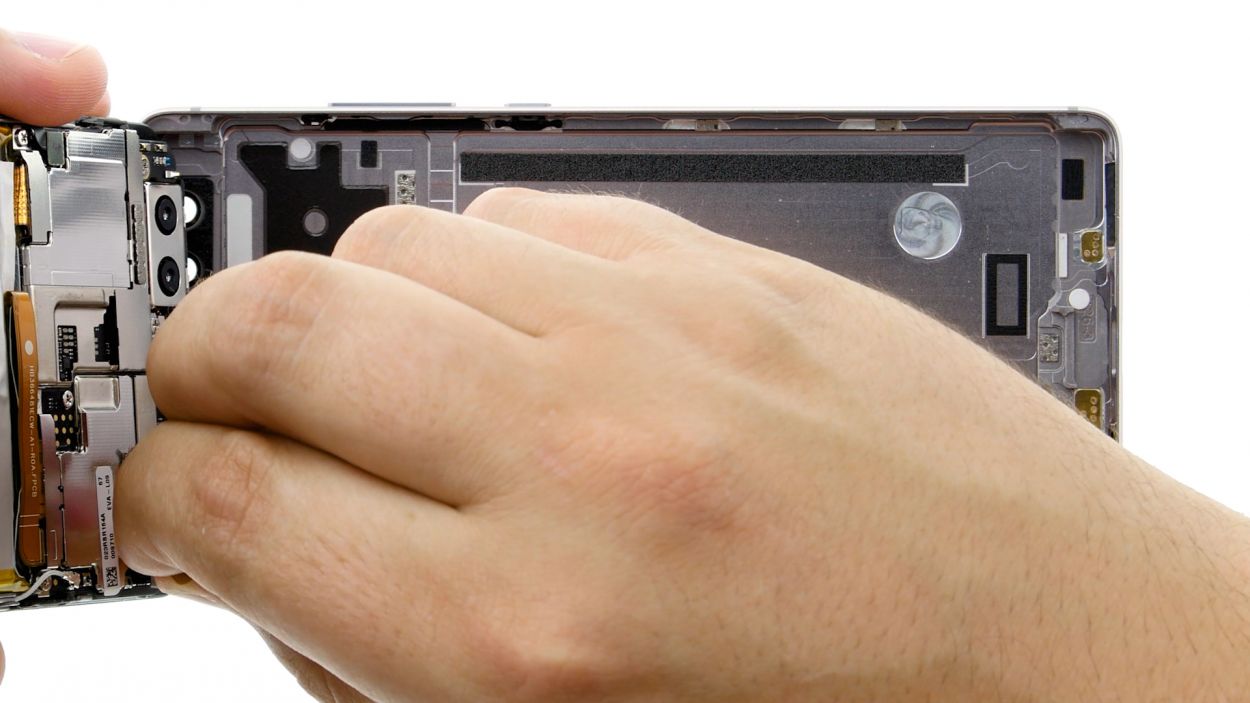
– With a bit of care, lift the display. Open the device slowly at the short upper edge, just like flipping a book. You should now see the connection cable.
– To disconnect the cable from the motherboard, carefully slide the spudger underneath the contact and disconnect it. Easy peasy!
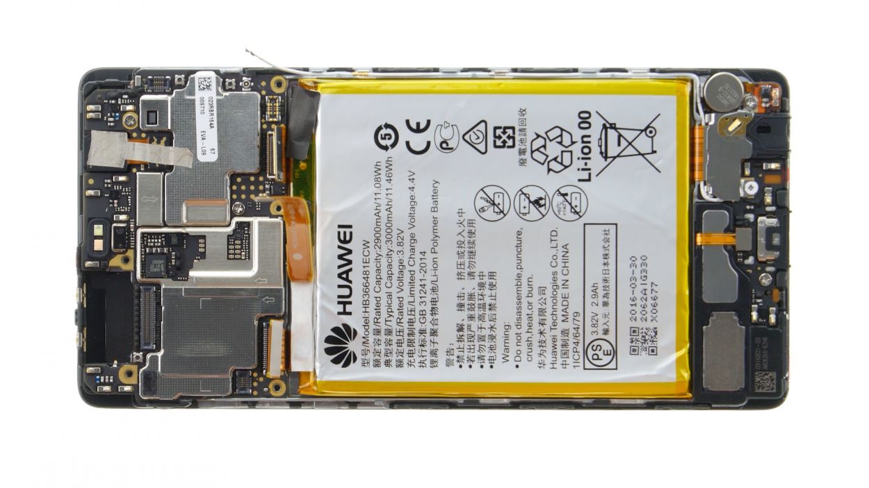
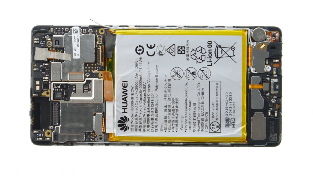
Step 5

2 × 2,5 mm PH00 Phillips-Schraube
Antenna Cable
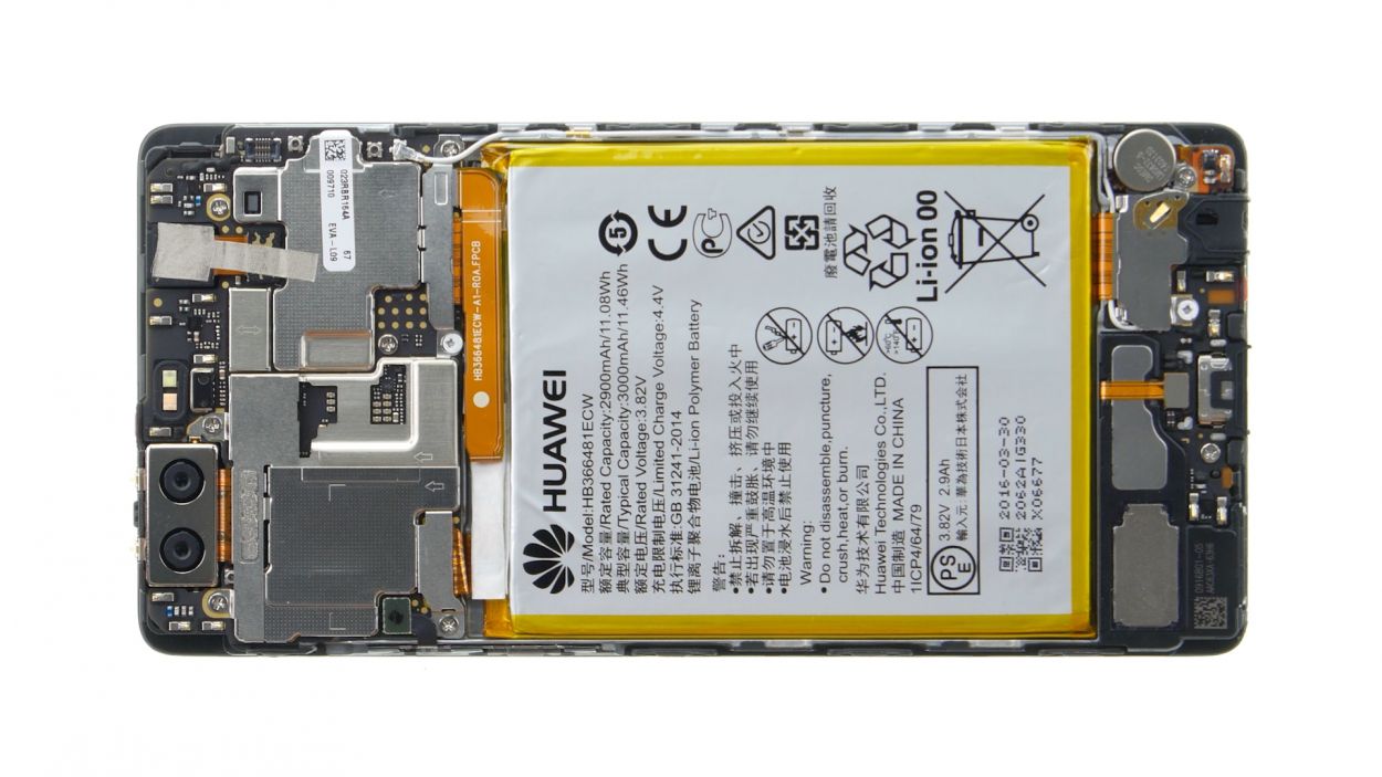
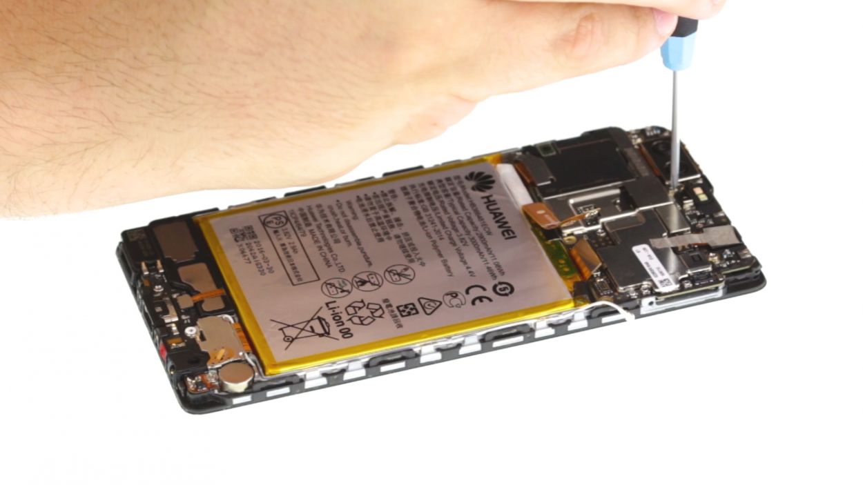
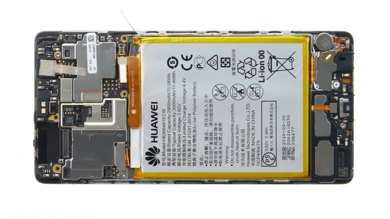
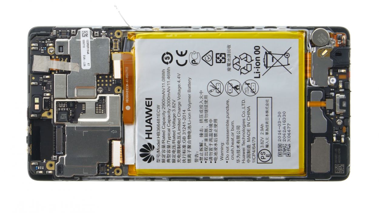
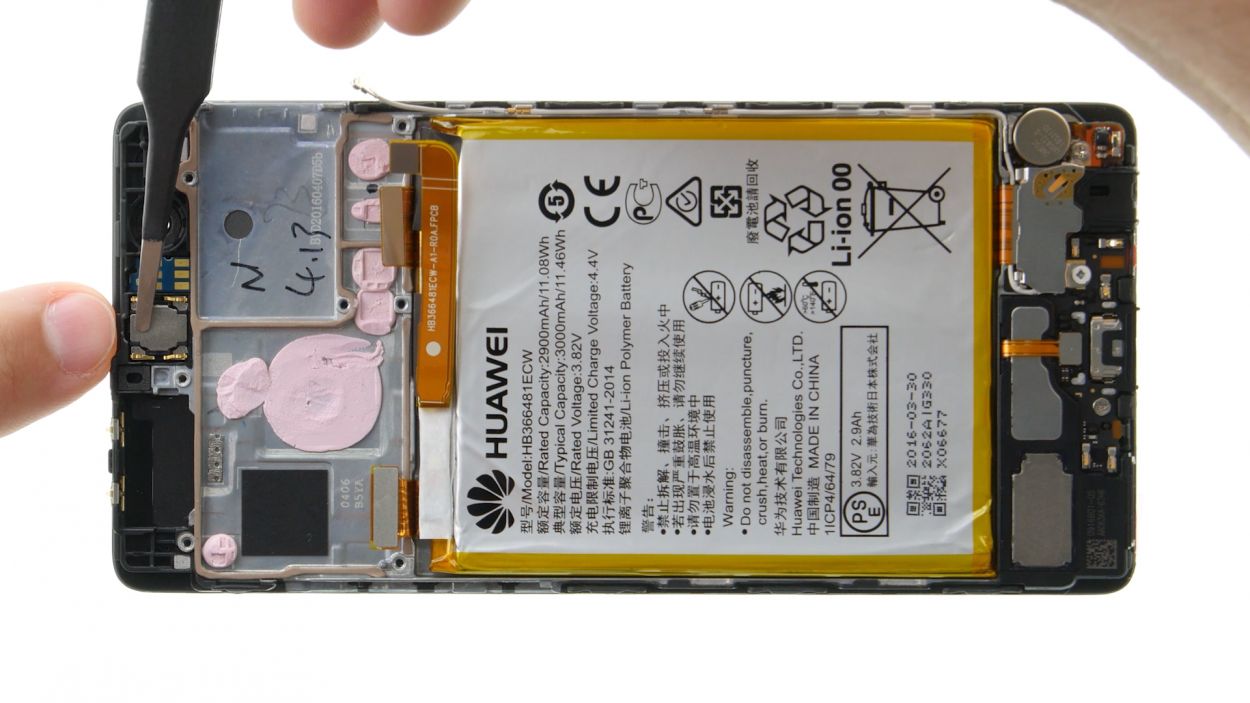
– First things first, let’s disconnect that white antenna cable from the motherboard to reveal the sneaky screw hiding underneath it.
– Next up, grab your trusty screwdriver and remove those two screws that are keeping the plate snug and secure.
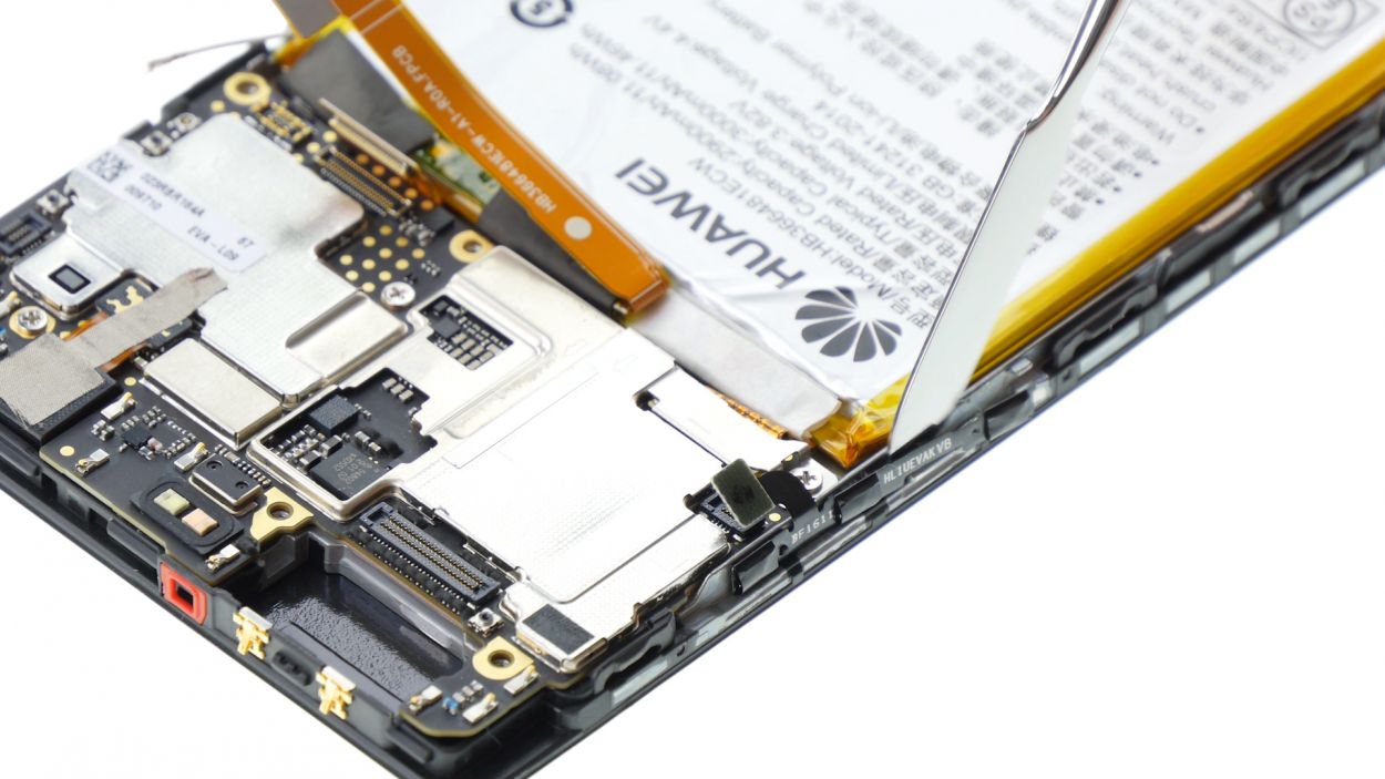
– Now, with the precision of a surgeon, use your tweezers to gently lift off the plate. It’s attached to the motherboard at both the screw holes and in the middle, so be careful!
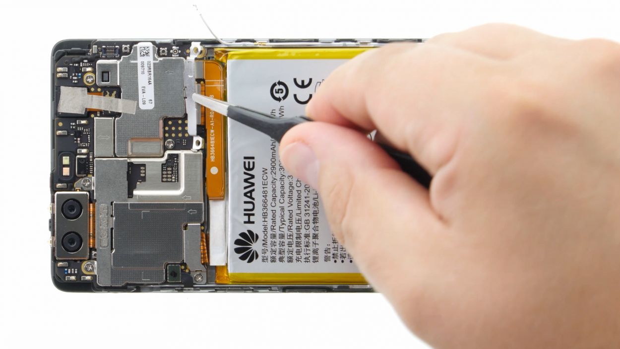
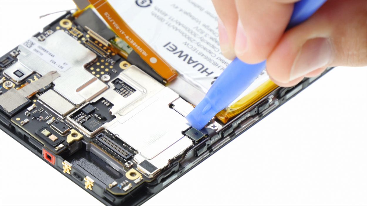
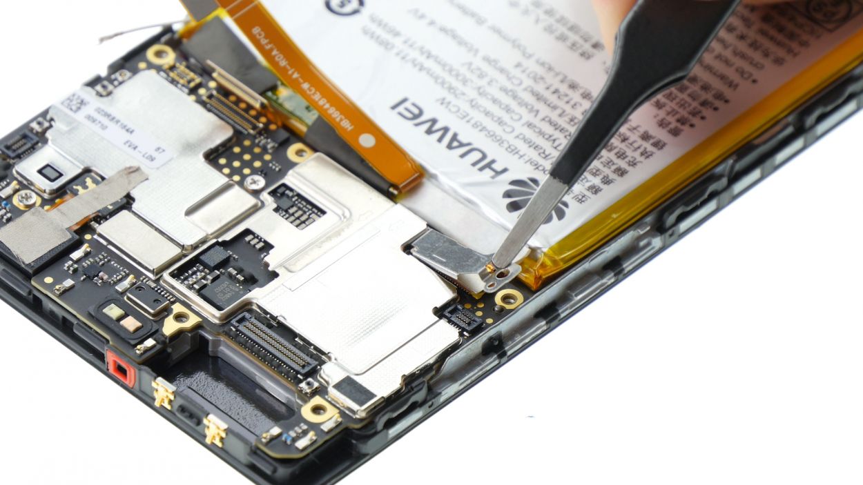
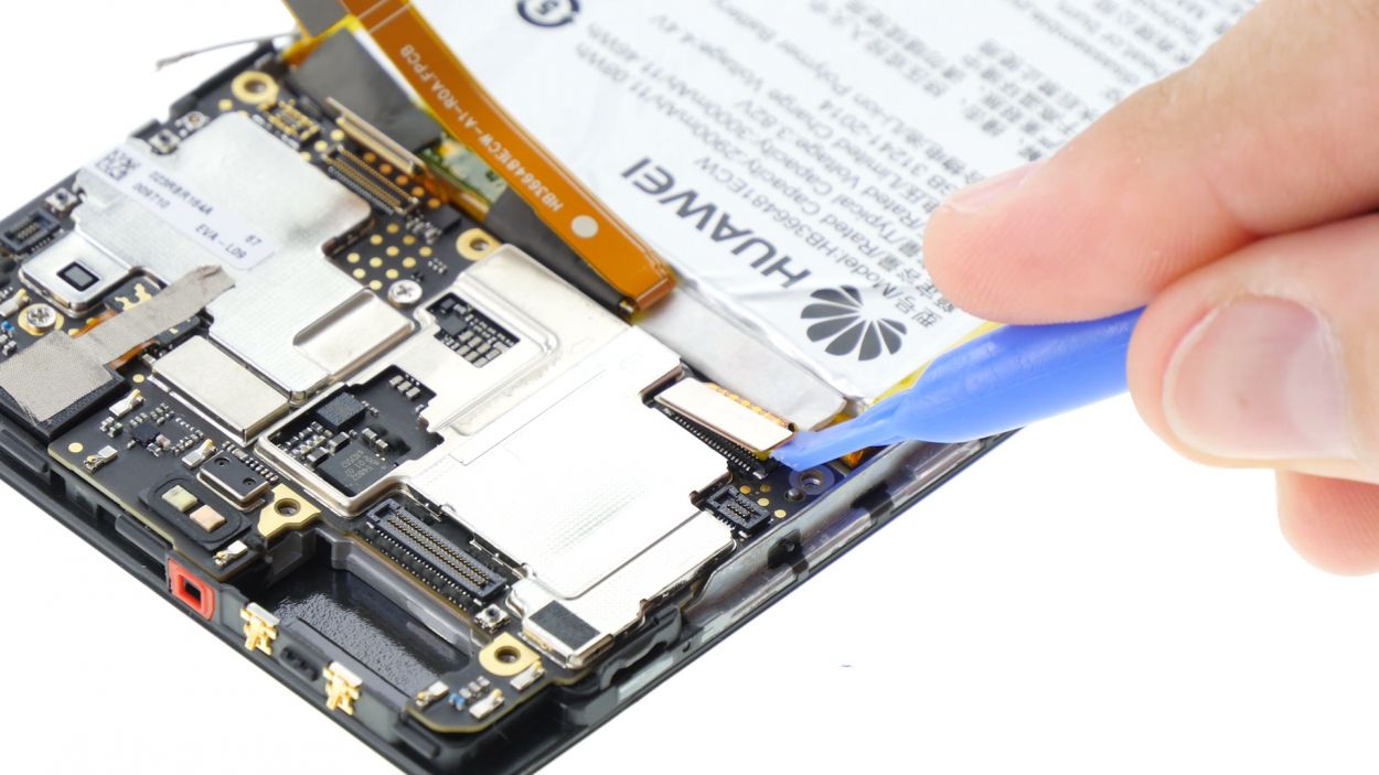
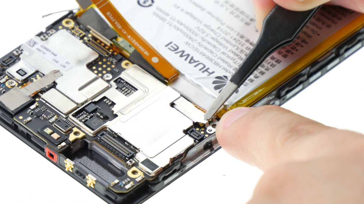
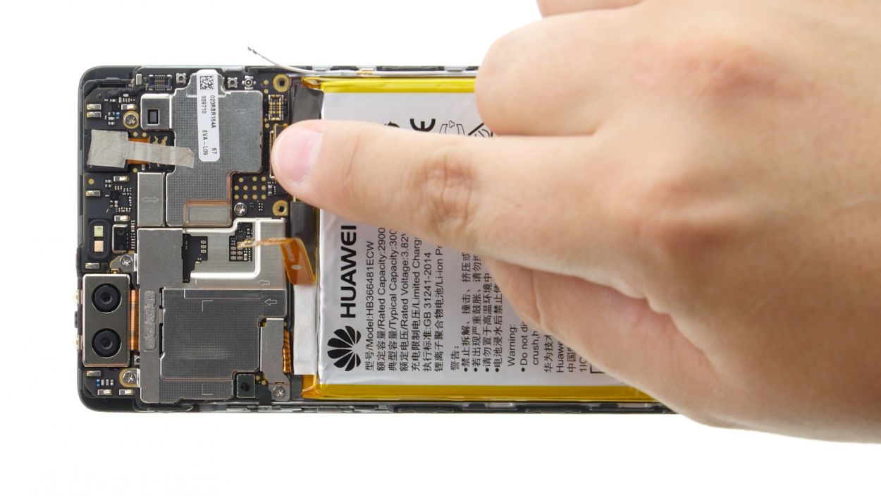
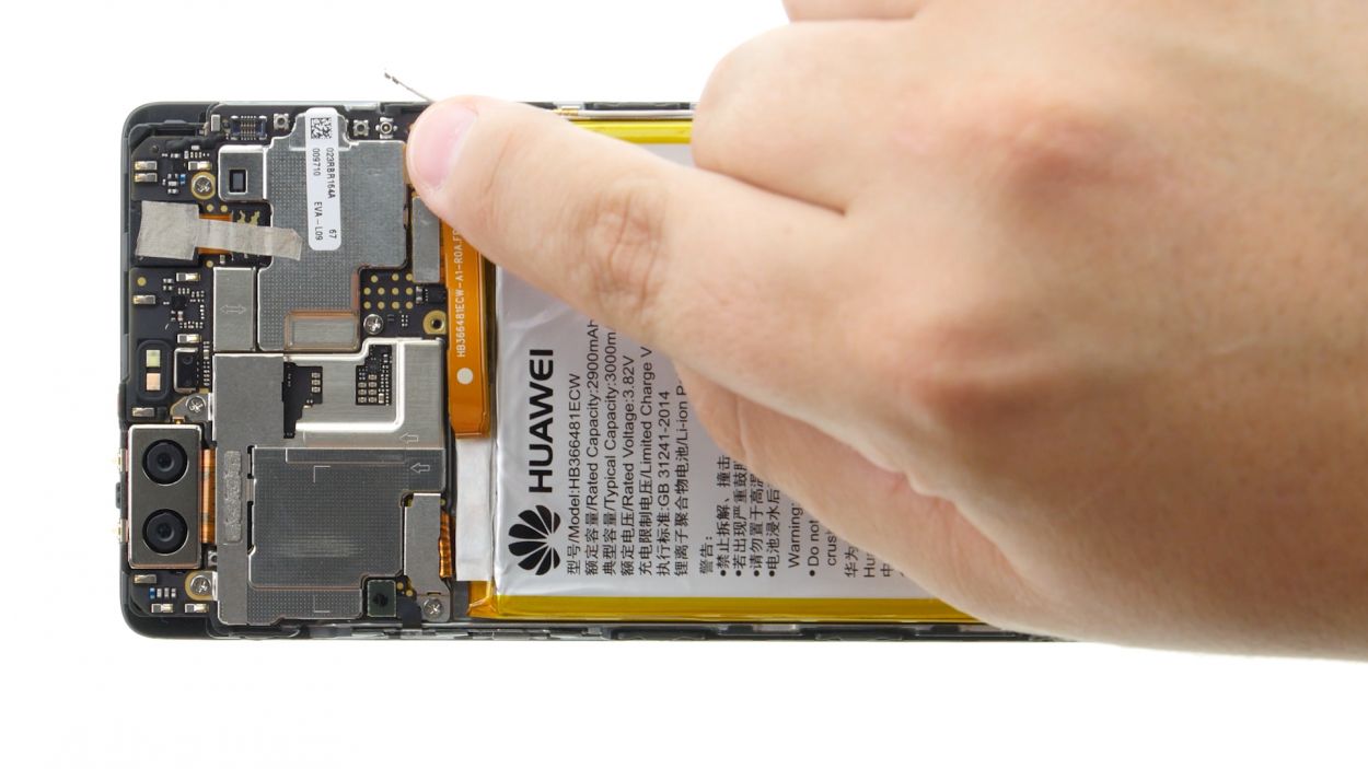
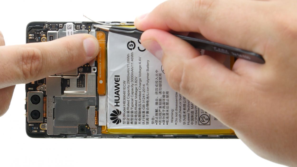
– Time to bring in the spudger! Carefully disconnect the battery contact like a pro.
– Lastly, let’s disconnect the wide flexible flat cable that connects the lower board to the motherboard. You’ve got this!
Step 6

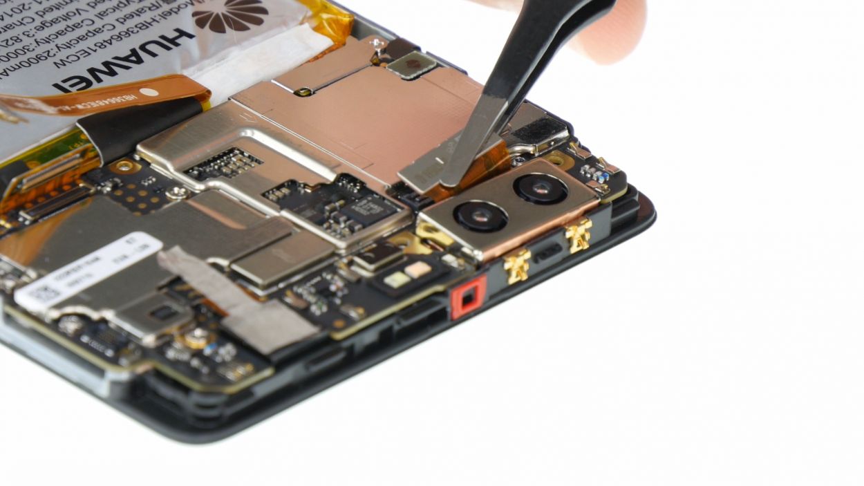
2 × 2,5 mm PH00 Phillips-Schrauben
– First things first, let’s tackle those two screws that are keeping the plate snug as a bug. Unscrew them and set them aside!
– Now that the screws are gone, gently lift off the plate. You’re doing great!
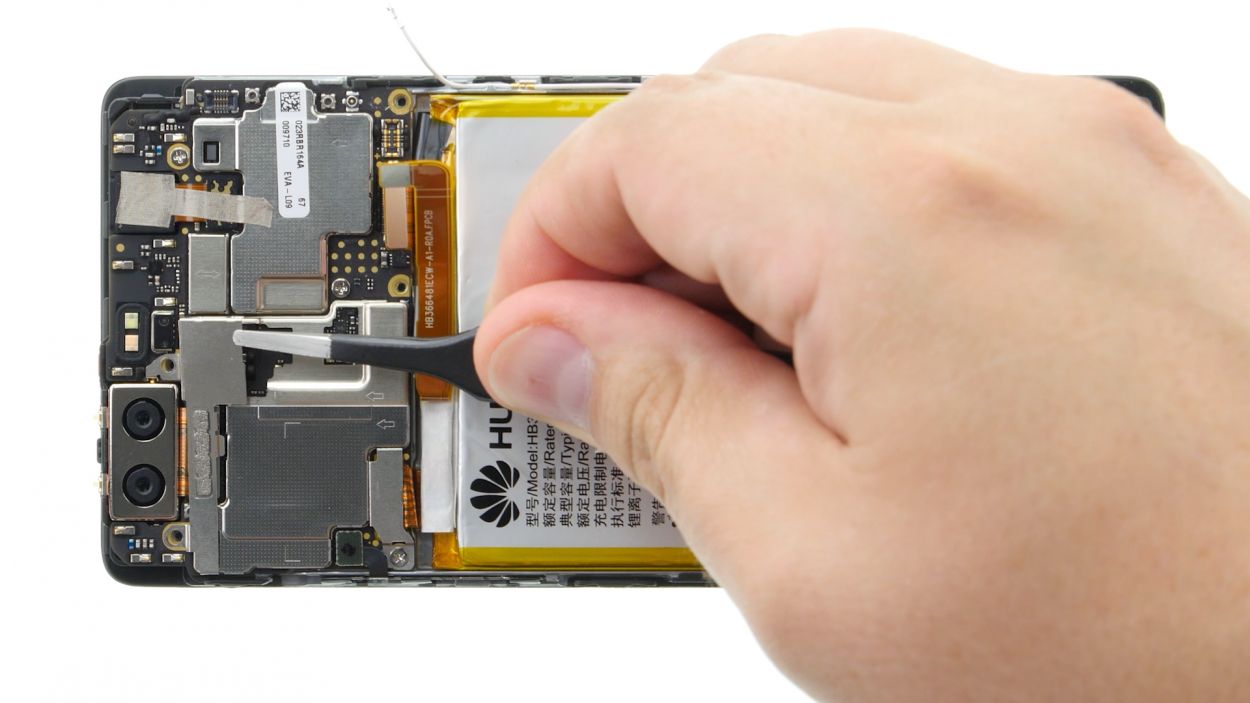
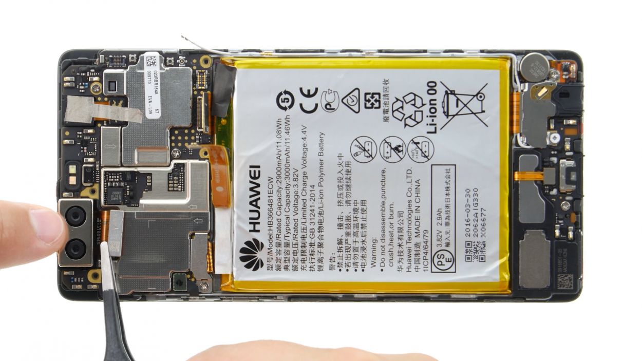
– Next up, it’s time to disconnect the camera’s plug from the motherboard. Grab your trusty spudger and slide it underneath that contact to pop it off.
– Finally, remove the camera from its cozy little home in the enclosure. Almost there!
Step 7
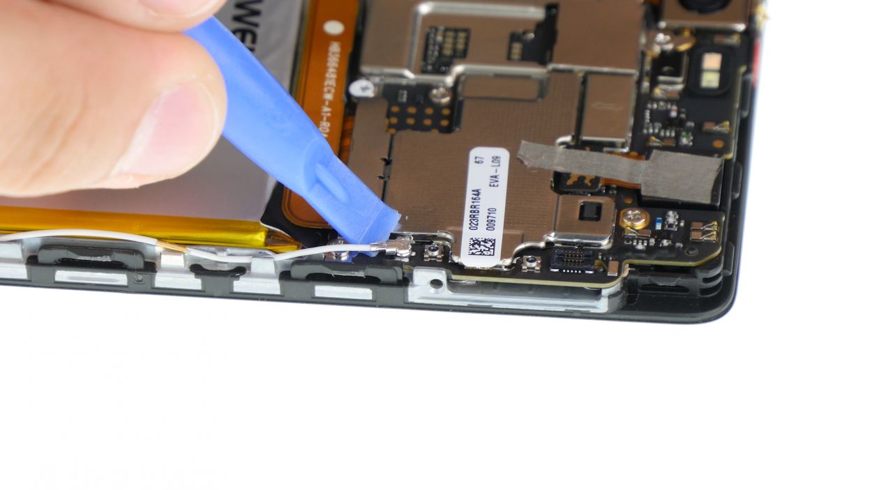
– First things first, let’s disconnect that connection to the motherboard and give it a little breather.
– Now, the control buttons are having a bit of a sticky situation with the display frame. Grab your trusty steel spatula and gently slide it between the buttons and the frame, starting on one side.
– Once you’ve got one side sorted, head on over to the other side and do the same.
– Finally, it’s time to say goodbye to those buttons and remove them with care!
Step 8
1 × 2,5 mm PH00 Phillips-Schraube
– Let’s kick things off by unscrewing that little screw keeping the plate snugly in place. You’ve got this!
– Next up, gently lift the plate off the motherboard like you’re unveiling a surprise gift.
– Now, it’s time to disconnect the display contact from the motherboard. Grab your trusty spudger and slide it into the edge of the plug contact. Give it a gentle nudge to pop it out of the socket. Easy peasy!
Step 9
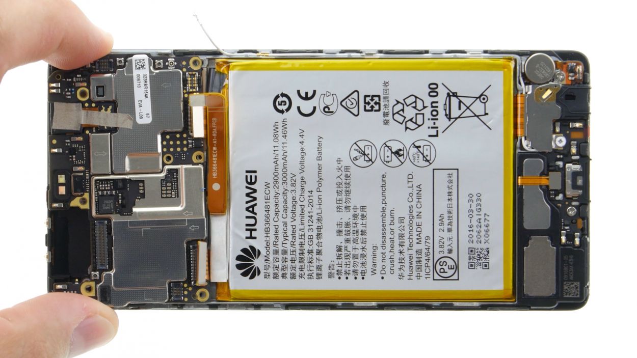
2 × 2,5 mm PH00 Phillips-Schrauben
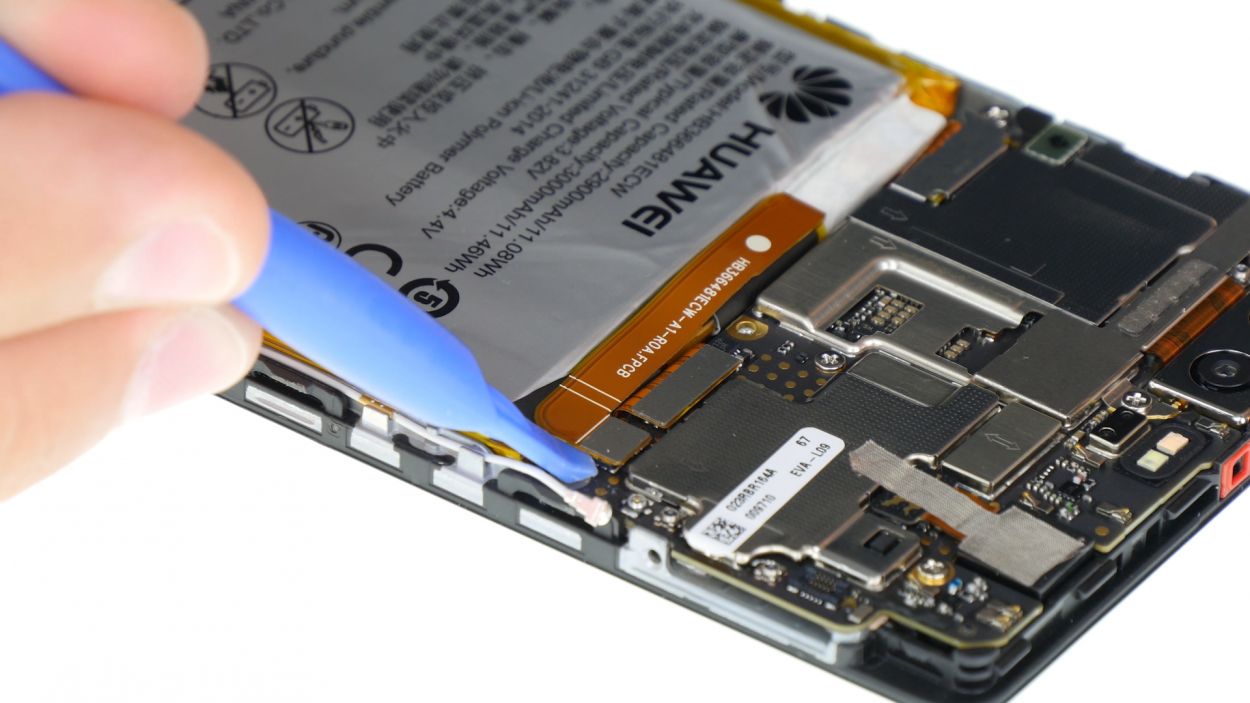
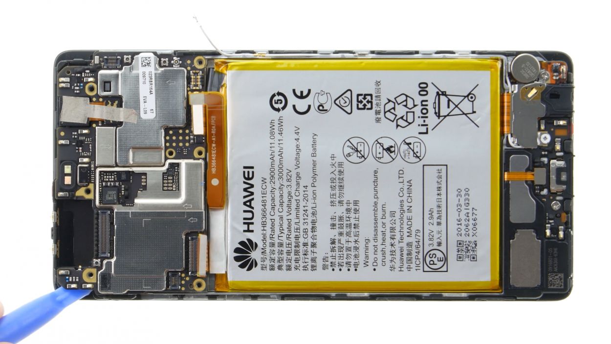
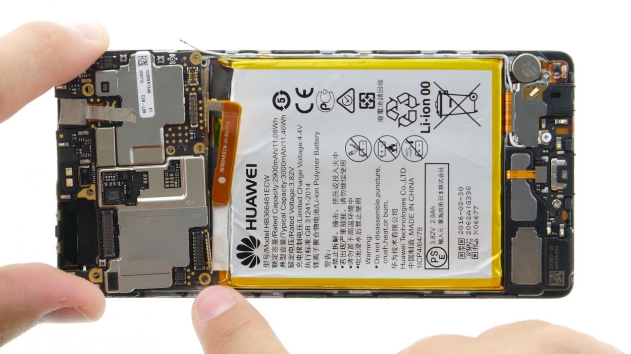
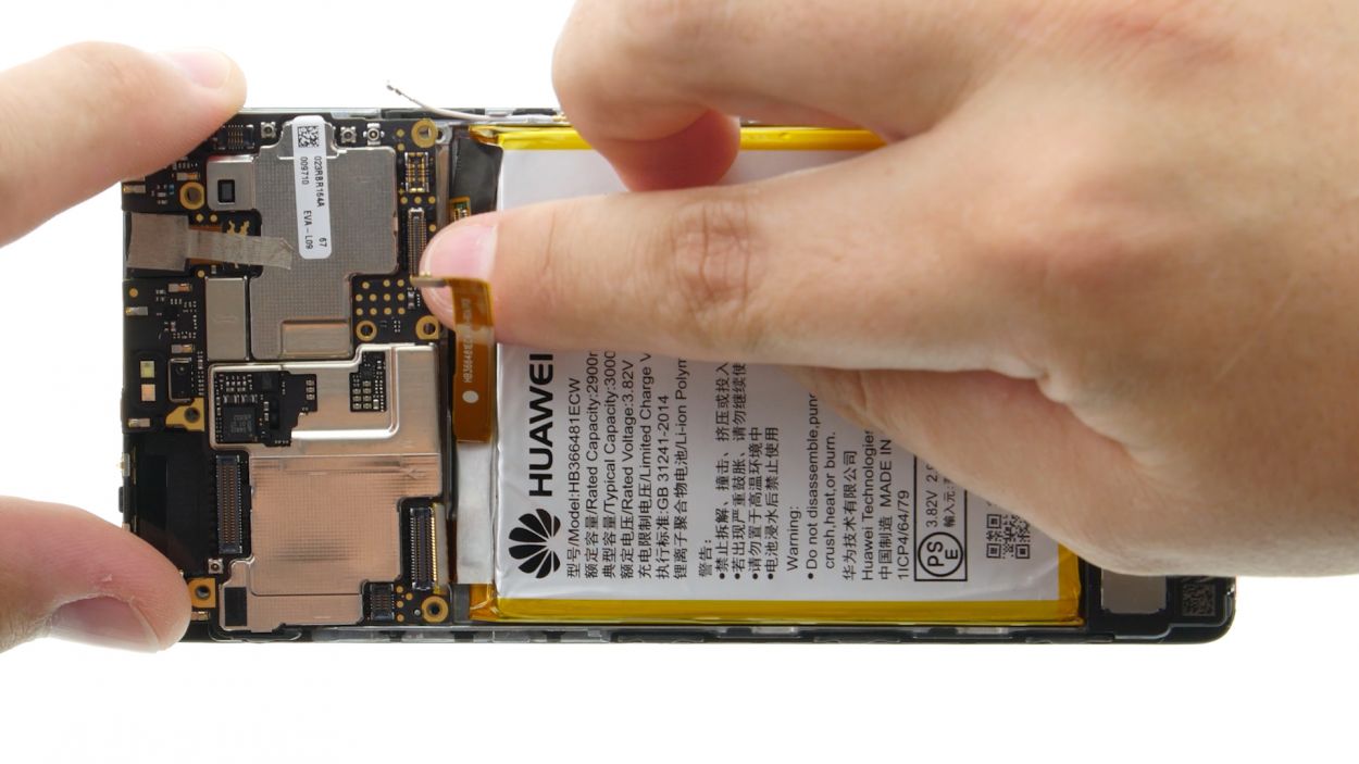
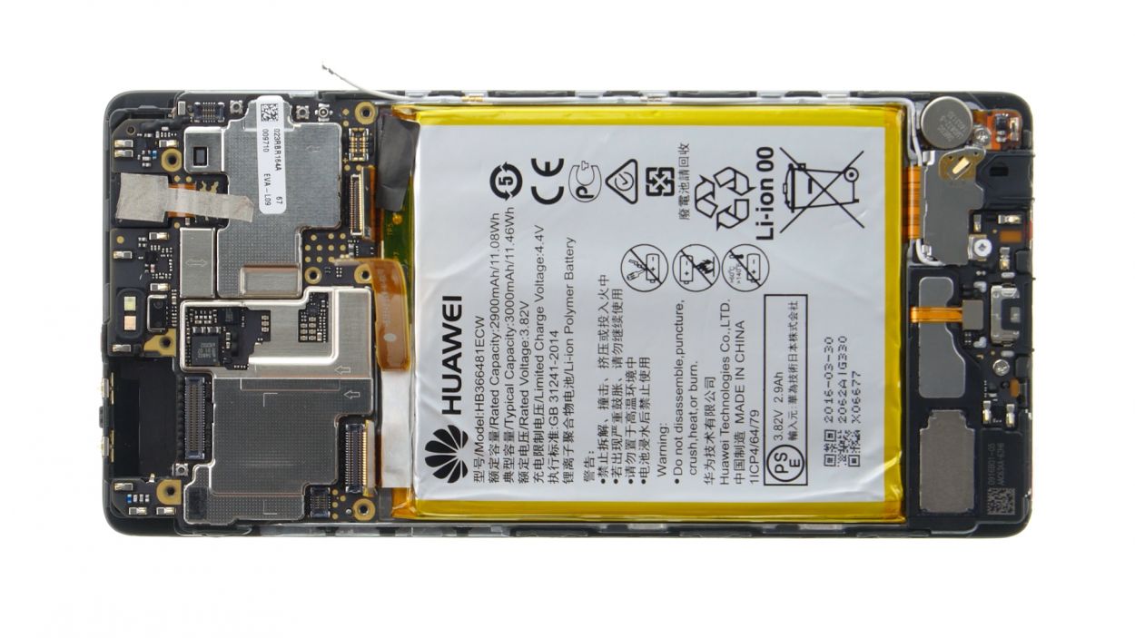
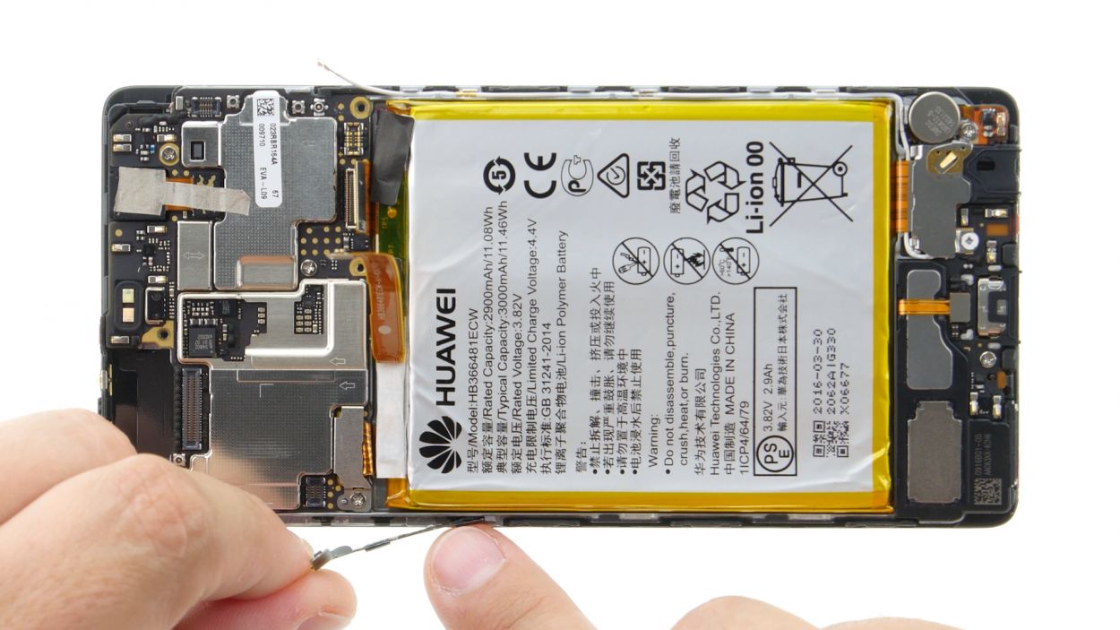
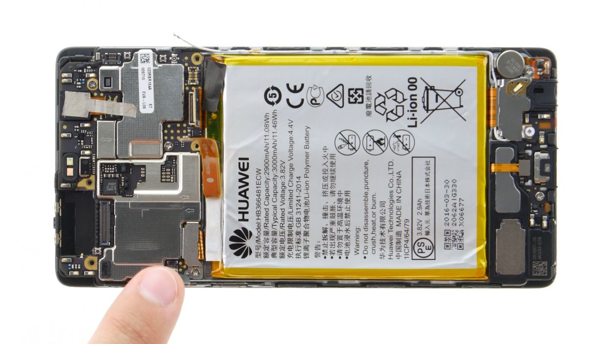
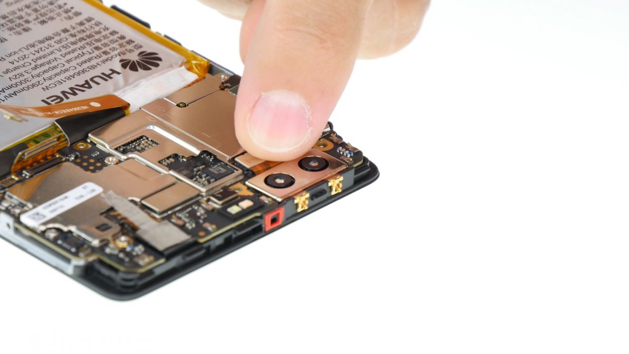
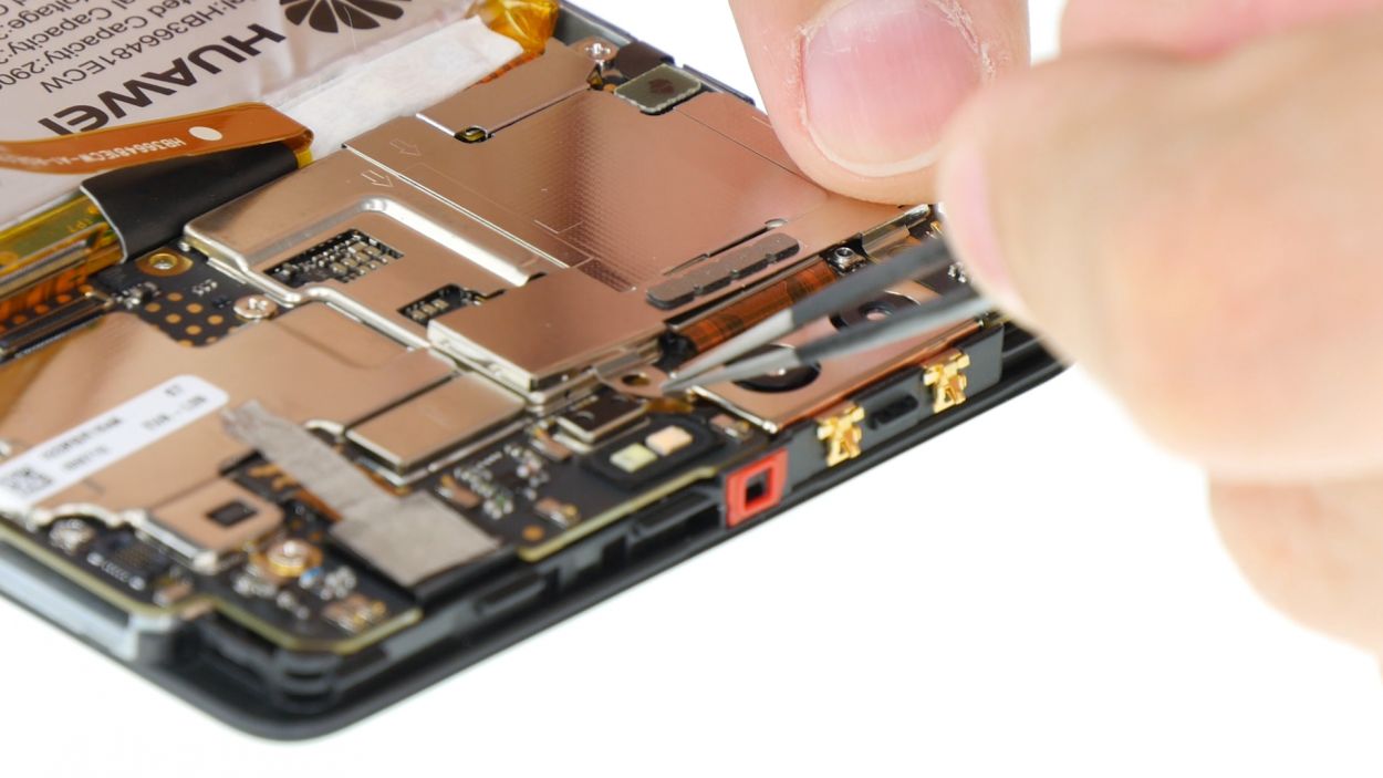
– First up, we’ve got two screws holding the motherboard snugly in the enclosure. Let’s get those screws out of the way!
– Next, the board is also secured in place. Grab your trusty spudger and gently slide it into the middle of the right side to free it up.
– Now, for the next move, position the spudger in the upper left corner and carefully pry the board out.
– And there you have it! Remove the board and you’re on your way.
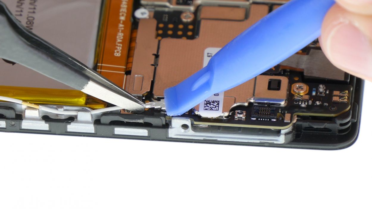
Step 10
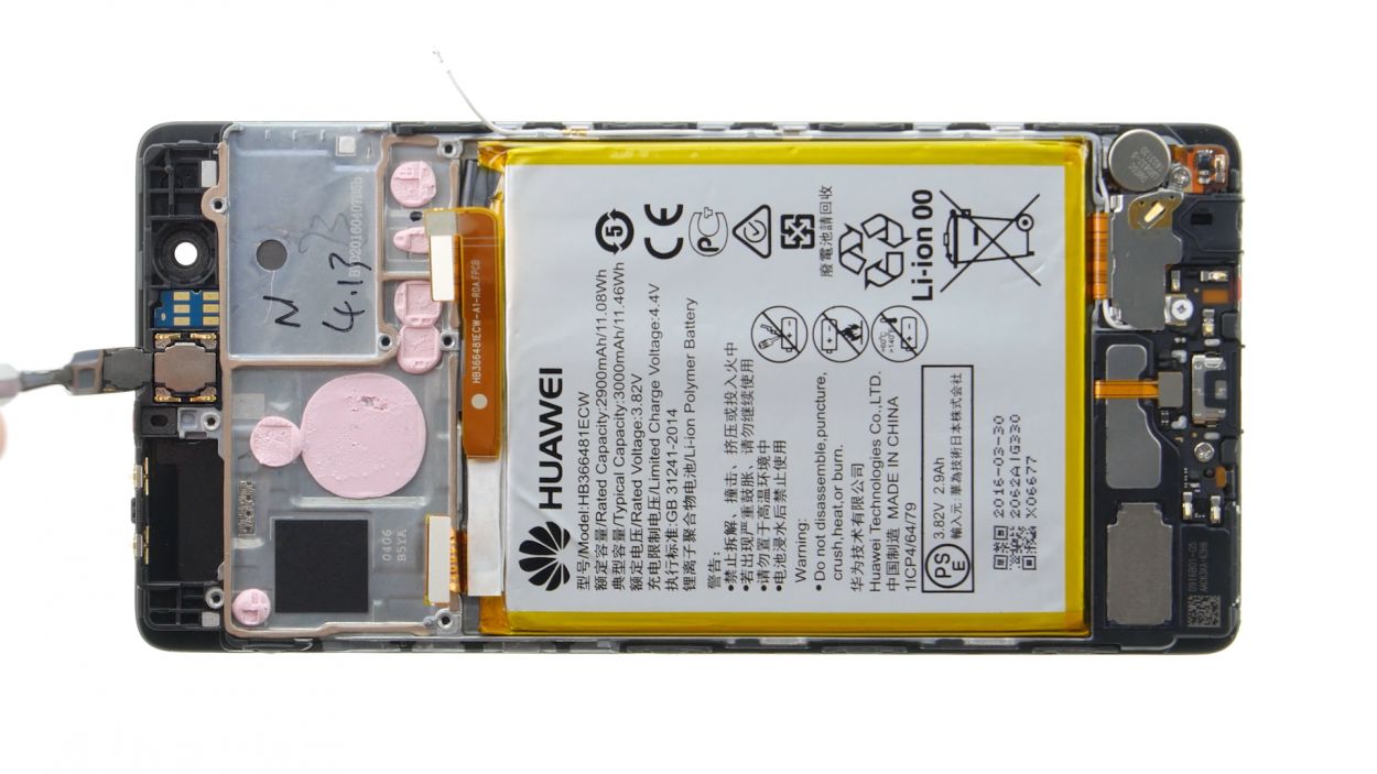
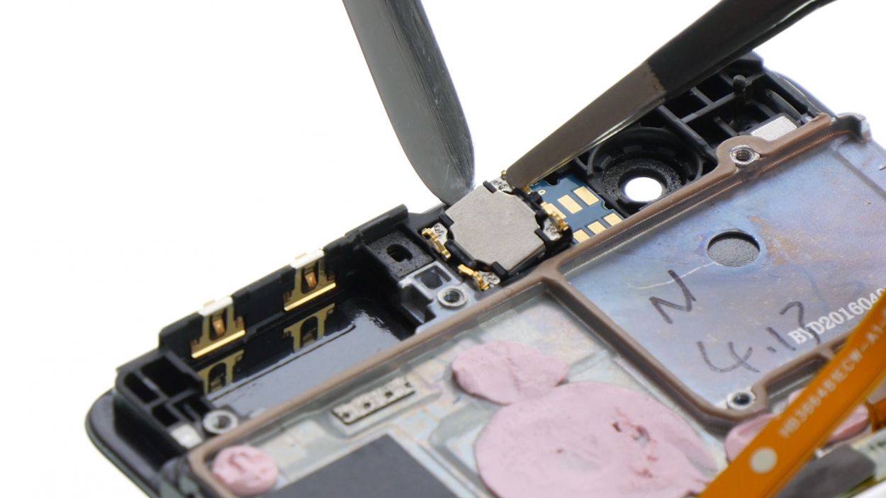
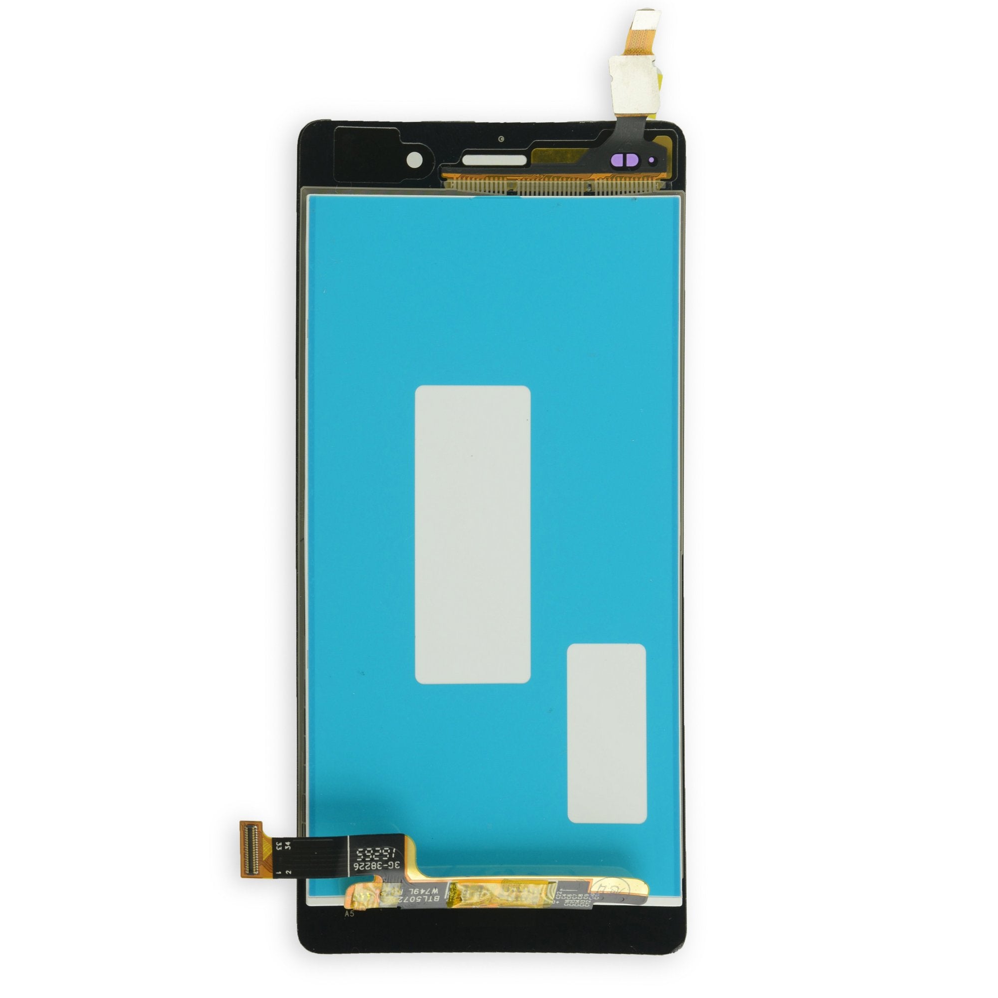
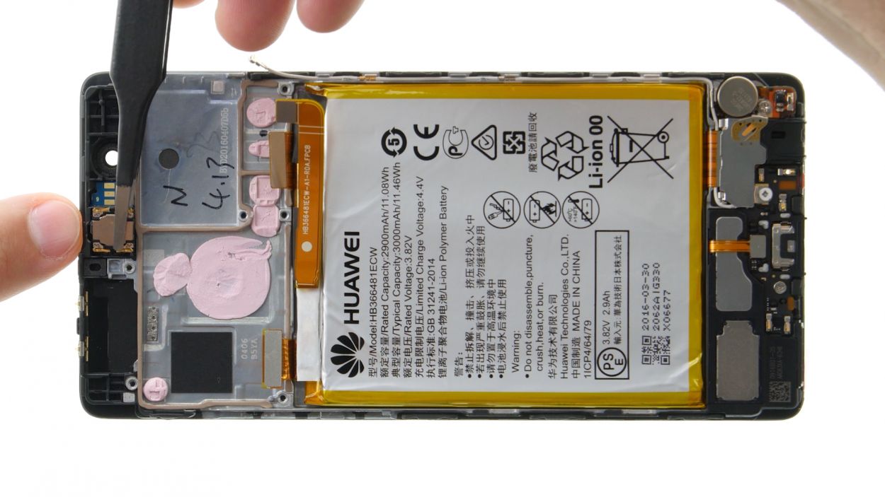
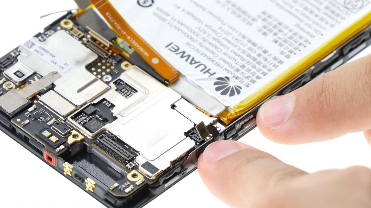
– The earpiece is snugly glued into its cozy little home, so let’s gently coax it out with a steel spatula. Slide that spatula in from the top and give it a careful nudge to pop it loose.
– Once it’s loosened up, simply lift the earpiece out of its snug spot in the enclosure.
Step 11
– Nestle the earpiece snugly into its little home.
– Give it a gentle press to help the glue grip better and create a solid seal.
Step 12
2 × 2,5 mm PH00 Phillips-Schrauben
– Slide that board back into its cozy home in the enclosure. Give it a gentle press until you hear that satisfying click!
– Check out the little holes—one’s up top on the right and the other’s down low on the left. Make sure a tab from the enclosure fits into each hole to help guide your board into place.
– Grab those two screws and secure the board to the enclosure. You’re almost there!
Step 13
Display Connector
1 × 2,5 mm PH00 Phillips-Schraube
– First up, connect that display contact to the motherboard like a pro!
– Next, pop the plate back onto the contact, making sure it fits snugly.
– Finally, grab the screw and secure that plate to the motherboard with confidence!
Step 14
– Let’s get those control buttons back on the frame! Use the little tabs on the frame to guide you into the right spots. Make sure those tabs fit snugly through the tiny round holes in the buttons.
– Now, give those buttons a good press! You want them to stick like they mean it, so the glue can do its job.
– Time to connect the plug contact to the motherboard. Make sure it’s snug and secure!
Step 15
2 × 2,5 mm PH00 Phillips-Schrauben
– Slide that camera right into its cozy enclosure!
– Gently connect the contact to the motherboard by pressing the connector into the socket like it’s a puzzle piece.
– Time to secure things! Place the plate back on to keep that contact snug as a bug.
– Grab those two screws and fasten the plate down tight; we want everything to stay put!
Step 16
2 × 2,5 mm PH00 Phillips-Schrauben
– Gently press the wide flexible flat cable into the motherboard’s socket until you hear that satisfying click. It’s like a high-five for your device!
– Next up, let’s reconnect the battery. It’s time for a power reunion!
– Now, place the plate back on to secure those contacts. Make sure it hooks on both the screw holes and the middle – it’s all about that perfect fit.
– Tighten it up with the two screws to keep everything snug and secure.
– Lastly, connect the antenna cable to the motherboard. We’re almost there!
Step 17
– Start by placing the back cover at the short upper edge of the display and gently connect the fingerprint sensor’s contact. Listen for that satisfying click as it locks into place!
– Now, let’s seal the deal! Fold down the back cover and give the display a gentle press to close everything up.
Step 18
2 × 2,8 mm P1 Pentalob-Schrauben
– Grab those two screws hanging out at the bottom edge and snug them up to seal your device back together. You’ve got this!
Step 19
– Slide the SIM tray and any cards back into your device, ensuring that everything is snugly in place. You’ve got this!