How to Replace Speaker on Sony Xperia Z5 Compact – Step-by-Step Guide
Duration: 30 min.
Steps: 16 Steps
Hey there! Is your Sony Xperia Z5 Compact’s speaker on the fritz? Don’t worry, we’ve got you covered! In this easy-to-follow guide, we’ll walk you through the steps to replace your phone’s defective speaker. If your phone’s gone quiet or your ringtone’s MIA, this repair is just what you need. So, let’s get started! If you need help, you can always schedule a repair
Step 1

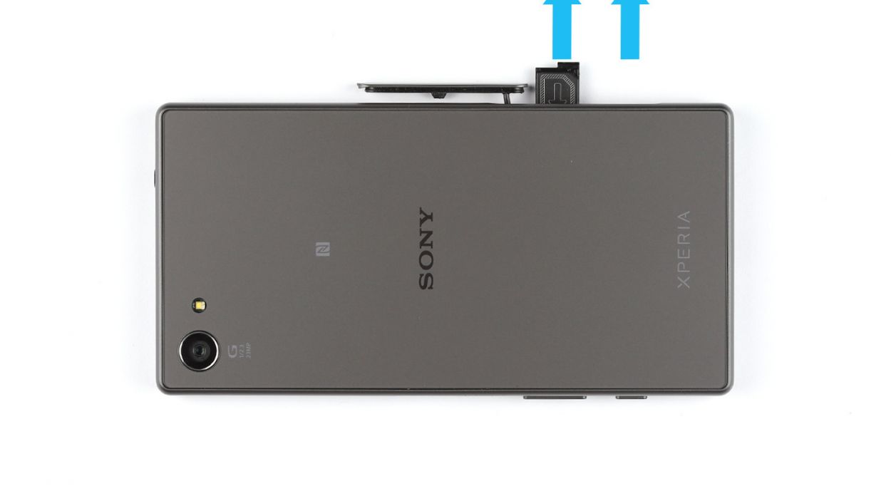
– Give that cover a gentle nudge with your finger or a spudger at the bottom of your smartphone. A little twist of 90° will help you peek into the card slot like a pro!
– Time to liberate those SIM and microSD cards! The SIM card is chillin’ in its tray, just waiting for you to set it free.
Step 2

The inside of the back cover has a little paint party going on! Gently remove any sticky residue to keep your device looking sharp and free from scratches or cracks.
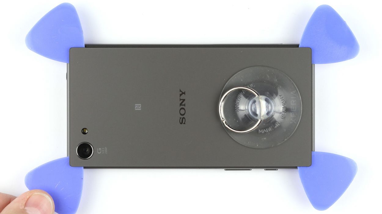
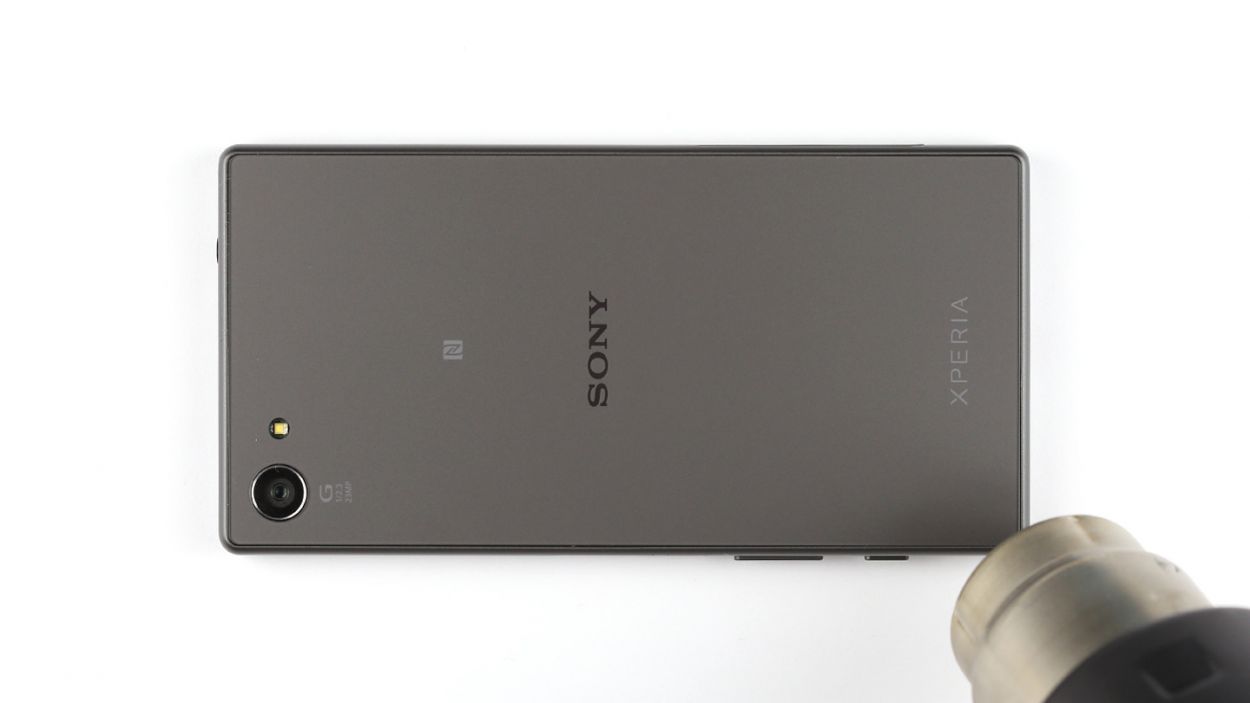
– The back cover is stuck on pretty tight, but don’t worry! Give it a little warmth with a heat gun to loosen that glue up.
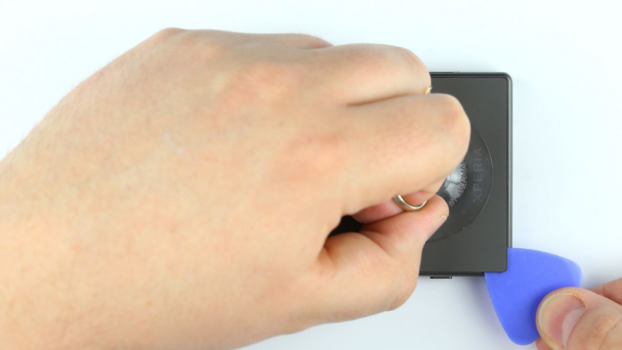
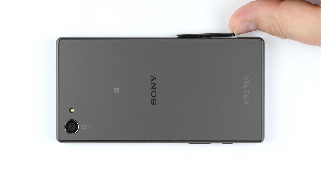
– Grab a suction cup and stick it to the bottom of your device. Pull gently while using a plastic pick to keep the chassis down. Teamwork makes the dream work!
– Once you see a little gap forming between the chassis and the back cover, slide that pick right in there. Just a heads up, the inside of the back cover is painted, so be careful when removing any leftover adhesive to avoid scratches or cracks.
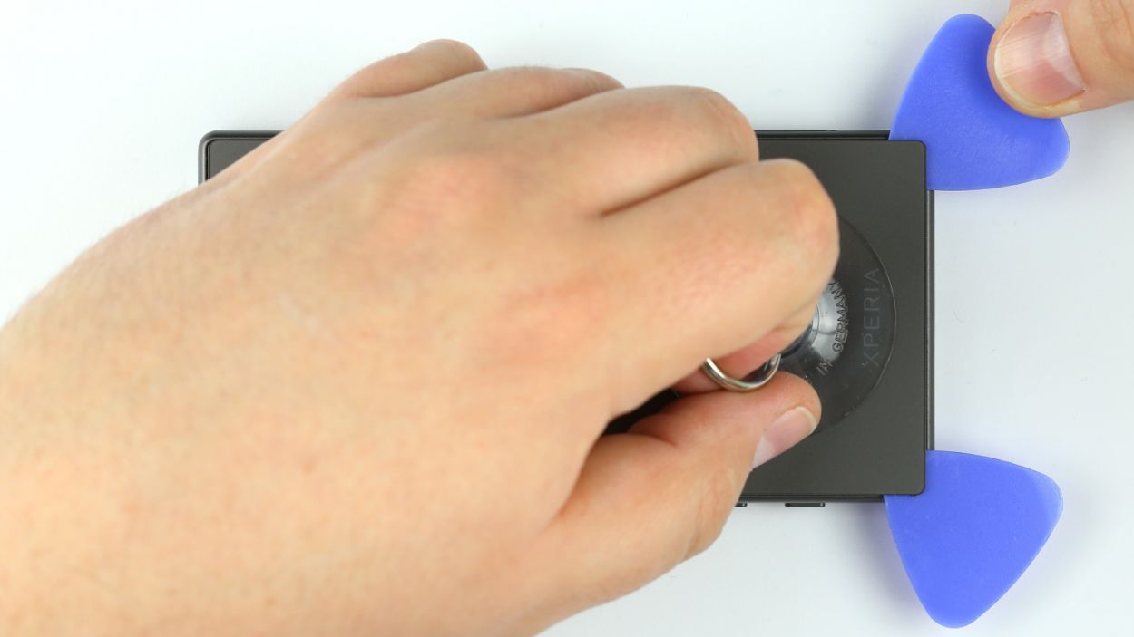
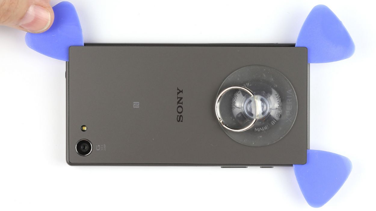
– Run the pick all the way around the device to fully detach the glue. If you’ve got extra picks, feel free to pop one in at each corner for easier access.
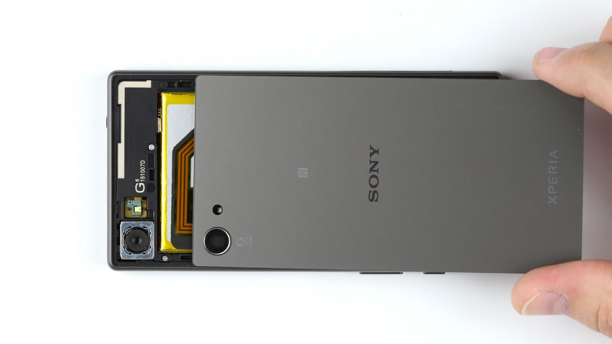
– Now, go ahead and lift off the back cover. You’re doing great!
Step 3

– Take off the type plate! It’s hanging out in the SIM and microSD card slot, just waiting for you to give it a little nudge.
Step 4
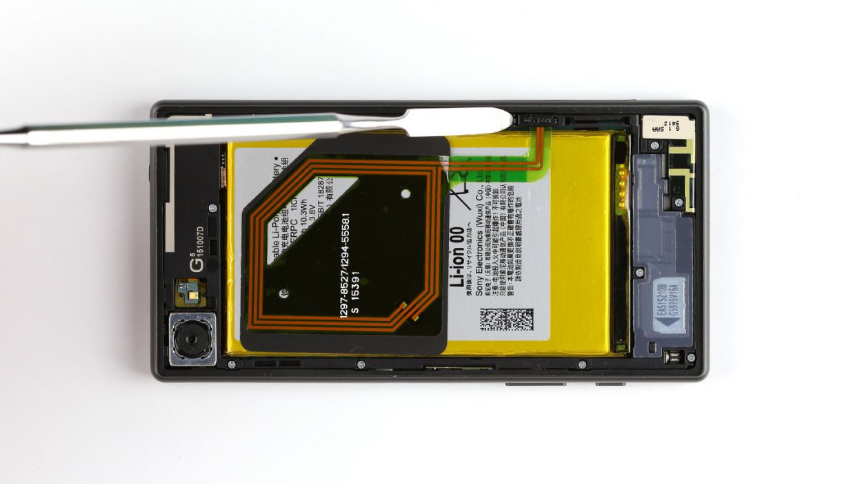
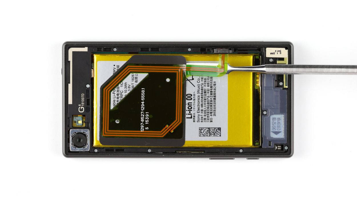
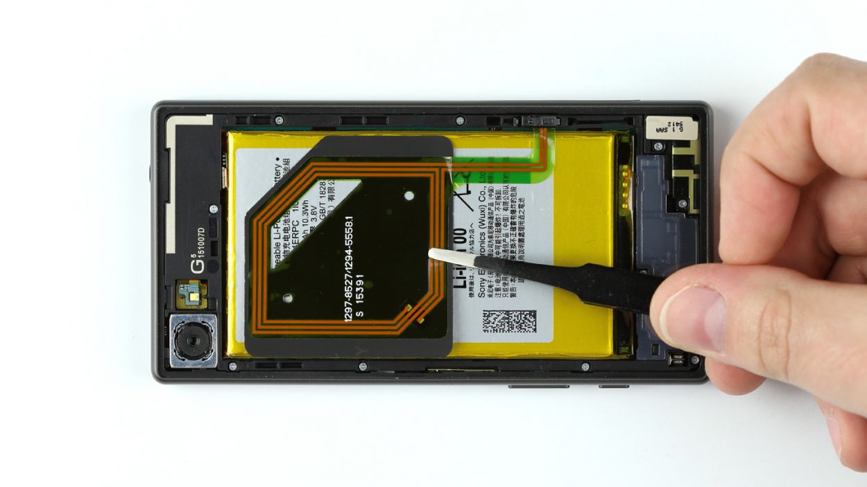
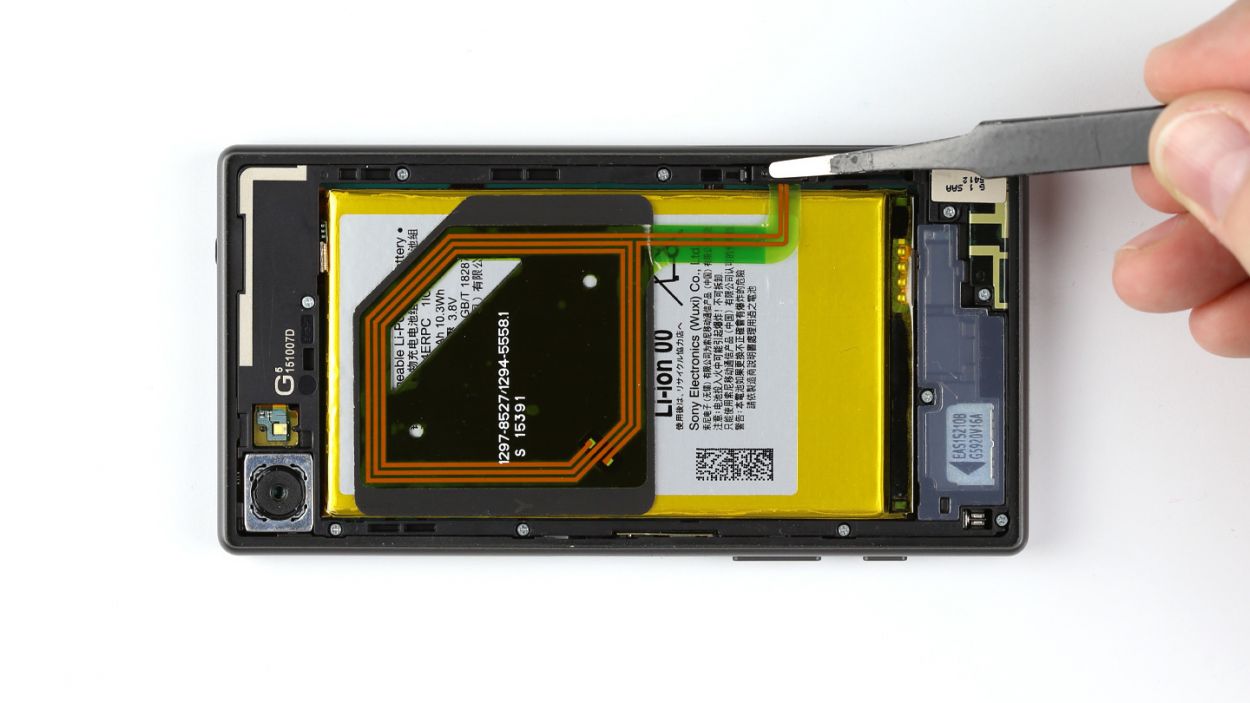
– First things first, gently unplug the NFC antenna from the chassis. Easy peasy!
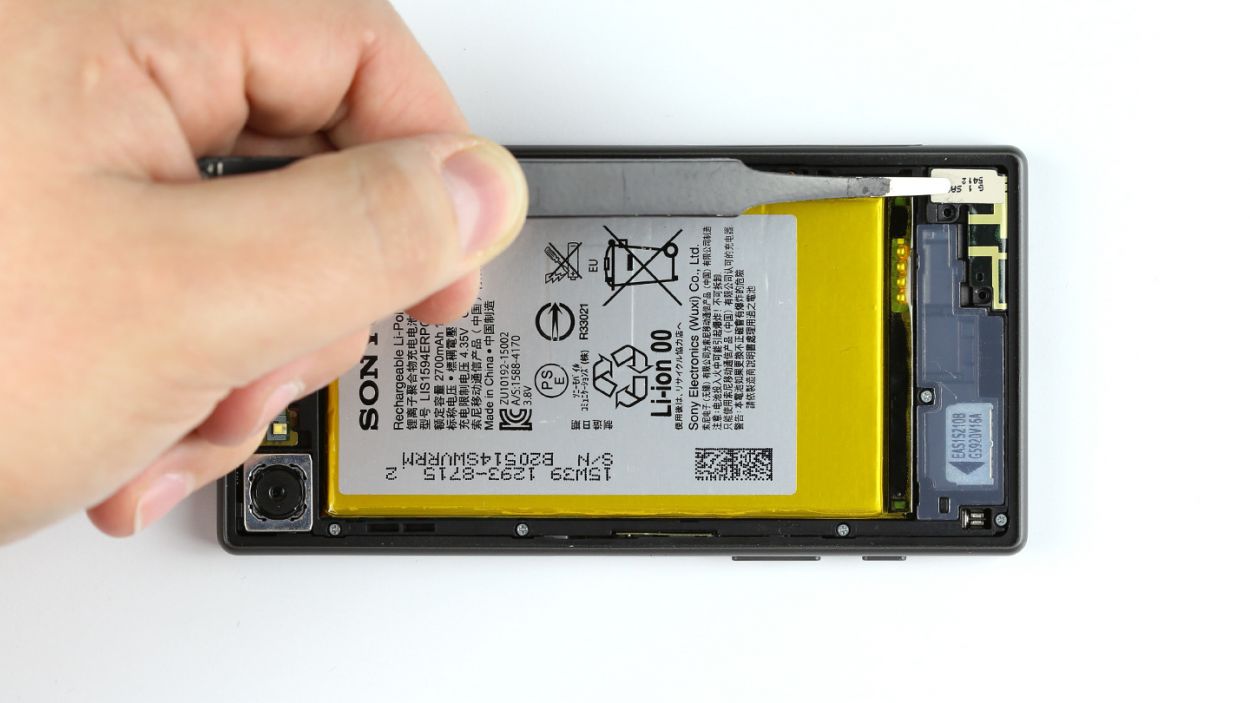
– Next up, it’s time to disconnect the antenna from the battery. Since it’s glued on there, grab a steel laboratory spatula and carefully slide it between the antenna and the battery. If the glue is being a bit stubborn, a little heat on the NFC antenna should do the trick.
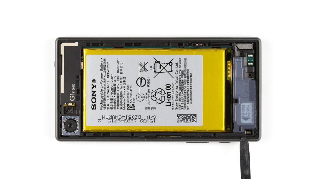
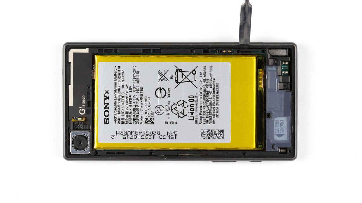
– Finally, go ahead and remove the NFC antenna. You’re doing great!
Step 5

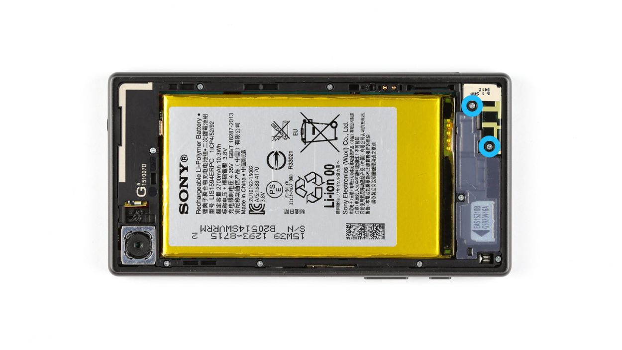
– Time to grab your trusty screwdriver! Start by loosening those two Phillips screws that are keeping the main antenna snug and secure. We’re talking about 2 x 4.5 mm Phillips screws here, so make sure you have the right size.
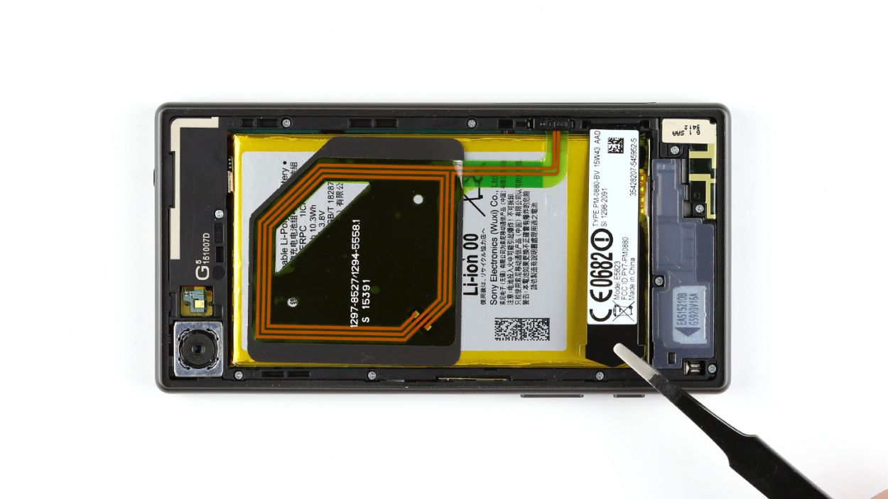
– Once those screws are out, gently lift the main antenna away from the device. You’re doing great!
Step 6


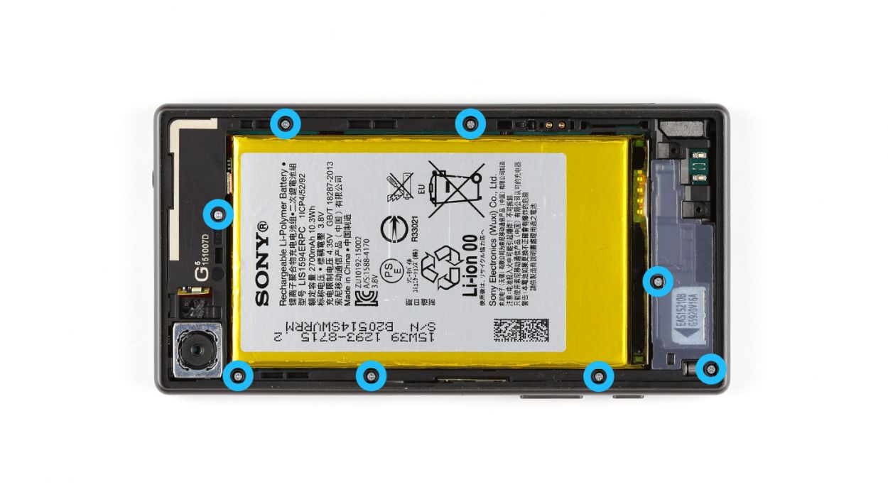
– Grab your trusty steel laboratory spatula and gently pry the LED flash away from the chassis. It’s stuck on there pretty good with some glue!
– Next up, let’s tackle those eight Phillips screws holding the chassis to the display. You’ll need 8 x 4.5 mm Phillips screws for this part.
– The chassis is snugly hooked onto the display. Use that steel spatula to carefully separate them. Just slide it in between the chassis and the display.
– Now, go ahead and remove the chassis!
Step 7
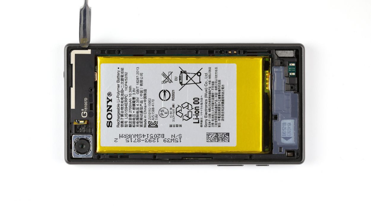
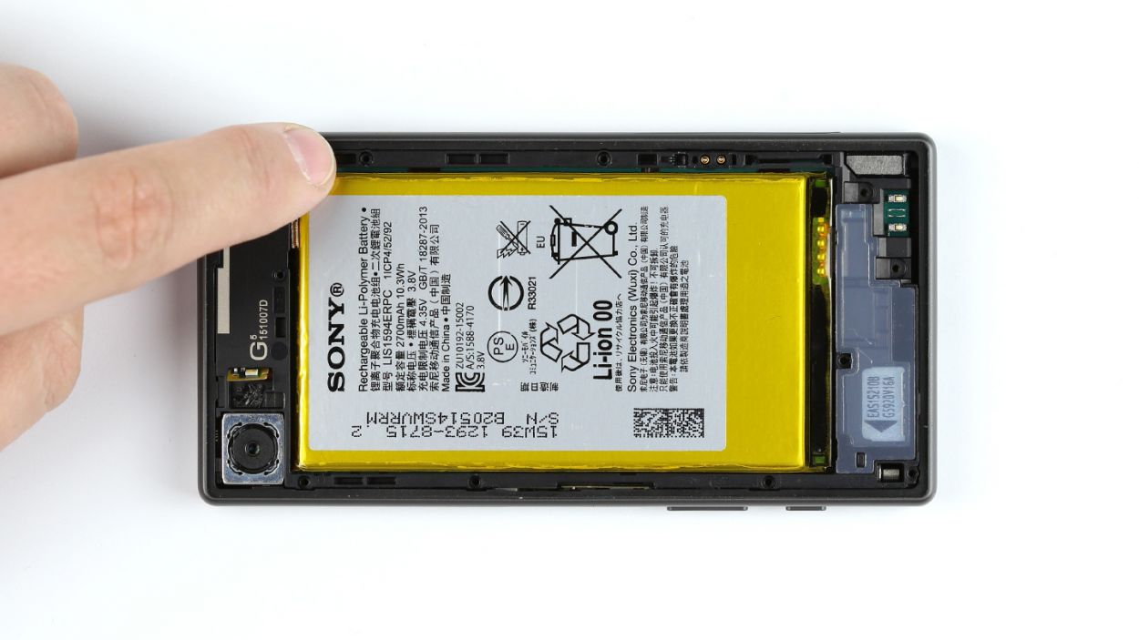
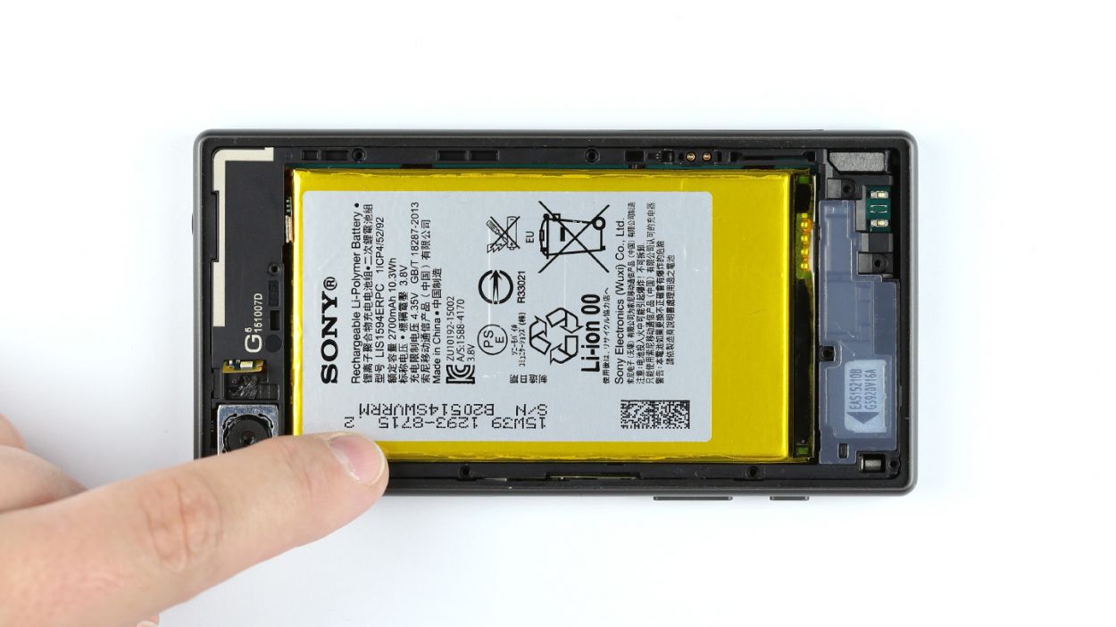
– Unplug the battery connector from the logic board and give it a little breather!
Step 8

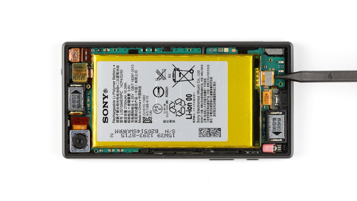
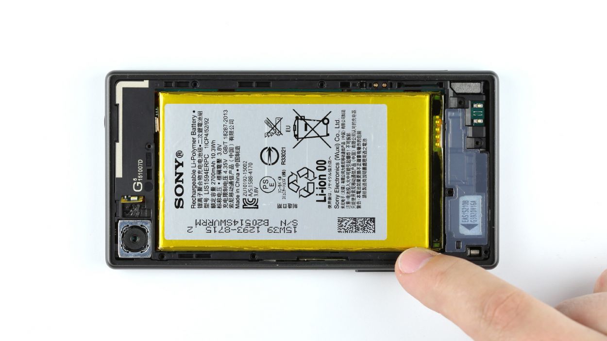
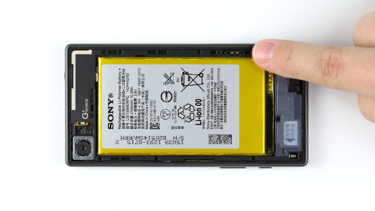
– Remove the speaker from the enclosure.
Step 9
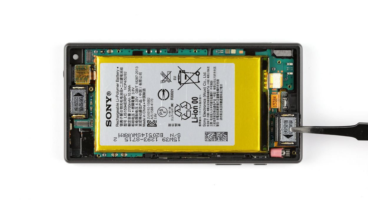
– Nestle the speaker snugly into the enclosure.
Step 10

– Go ahead and connect that battery contact to the logic board! You’ve got this!
Step 11


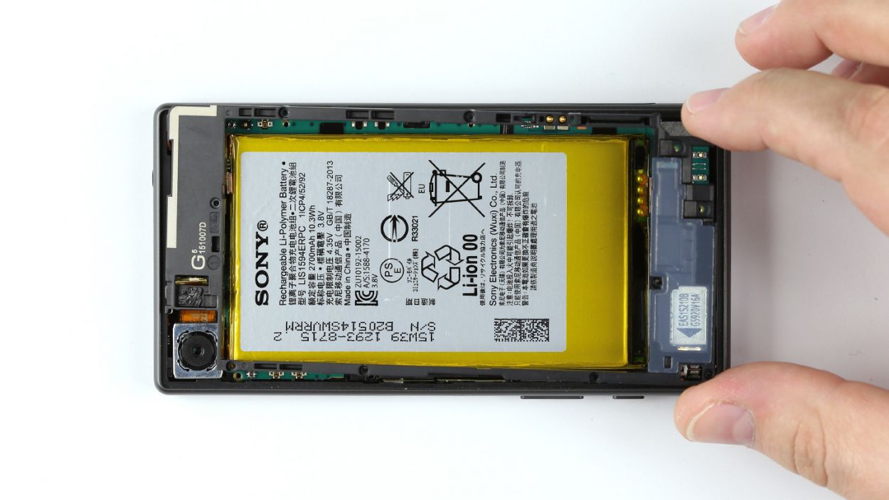
– Gently place the chassis on the display like it’s settling in for a cozy nap.
– Give the chassis a little press to make sure it clicks snugly into the display frame—it’s like giving it a warm hug!
– Secure the chassis to the display using those eight trusty Phillips screws—8 x 4.5 mm Phillips screws, to be exact. Tighten them up like you mean it!
– Now, let’s add some flair! Attach the LED flash to the chassis and watch it shine.
Step 12

– Get that main antenna snugly positioned inside the enclosure.
– Secure the main antenna to your device using those two trusty Phillips screws. Remember, we’re talking about 2 x 4.5 mm Phillips screws here!
Step 13

– Let’s get that NFC antenna cozy on the battery! Just press it down firmly so the glue can do its magic and stick like a pro.
– Now, it’s time to connect the NFC antenna’s plug to the chassis. Make sure it’s snug and secure!
Step 14
– Time to get that type plate in place! Just pop it into the SIM and microSD card slot and you’re all set.
Step 15

– Snap that back cover onto the chassis! Make sure it’s snug all the way around – we want a perfect fit!
– Need a little extra help? Gently warm the back of your device. This’ll help things stick nicely. A clamp can add some extra pressure to ensure a secure bond. If you need a hand, you can always schedule a repair.
Step 16

– If you find yourself closing the cover again, just give it a gentle nudge with your finger or grab your trusty spudger to pop it open. For an even better view of that card slot, try giving the cover a little twist of 90°!
– Now it’s time to slide those SIM and microSD cards back into their cozy homes. Just place the SIM card in its tray and you’re all set!

