DIY Guide to Replace Galaxy Note 8 Screen in 60 Minutes
Duration: 60 min.
Steps: 32 Steps
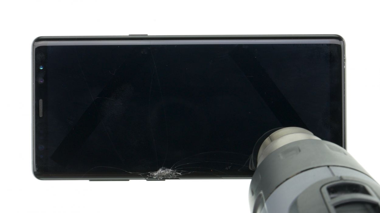
With this detailed step-by-step guide, you can easily replace your Galaxy Note 8 display at home.A replacement is necessary when the glass is shattered, the touchscreen does not respond to touch anymore, or the display remains black or flickers. During this repair, we replace the entire display unit including the frame, not just the broken screen. You may have to take some small parts from the old display unit, depending on how the new spare part is equipped.The repair is a bit difficult as the Galaxy Note 8 has to be opened via the glass backcover. Unfortunately, this is a rather cumbersome procedure, so plan enough time for it.Do a backup before the repair, use a clean work surface and reserve enough time. If you are stuck at any point, just contact our live chat or write a comment on the corresponding step.
Step 1
Don’t worry, it’s time to breathe a sigh of relief! Our experts at Salvation Repair are here to help you get back to your fabulous phone or tablet in no time. Check out our schedule a repair to get started!
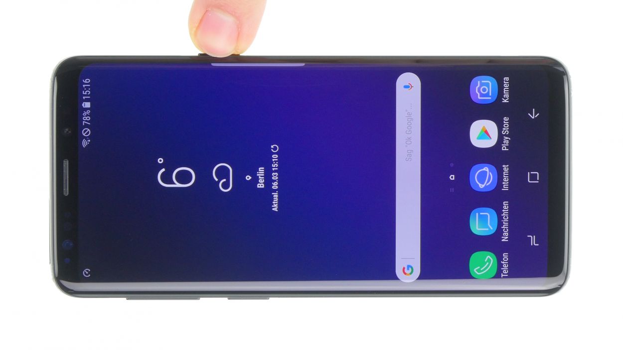
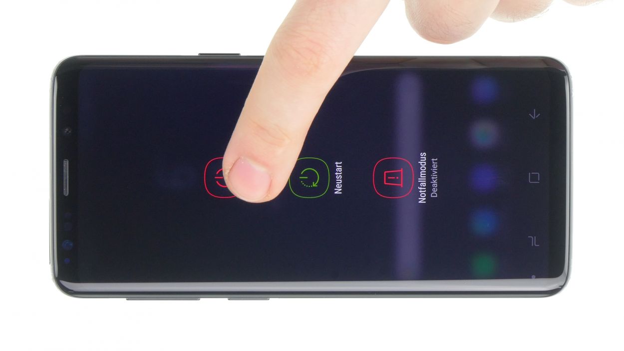
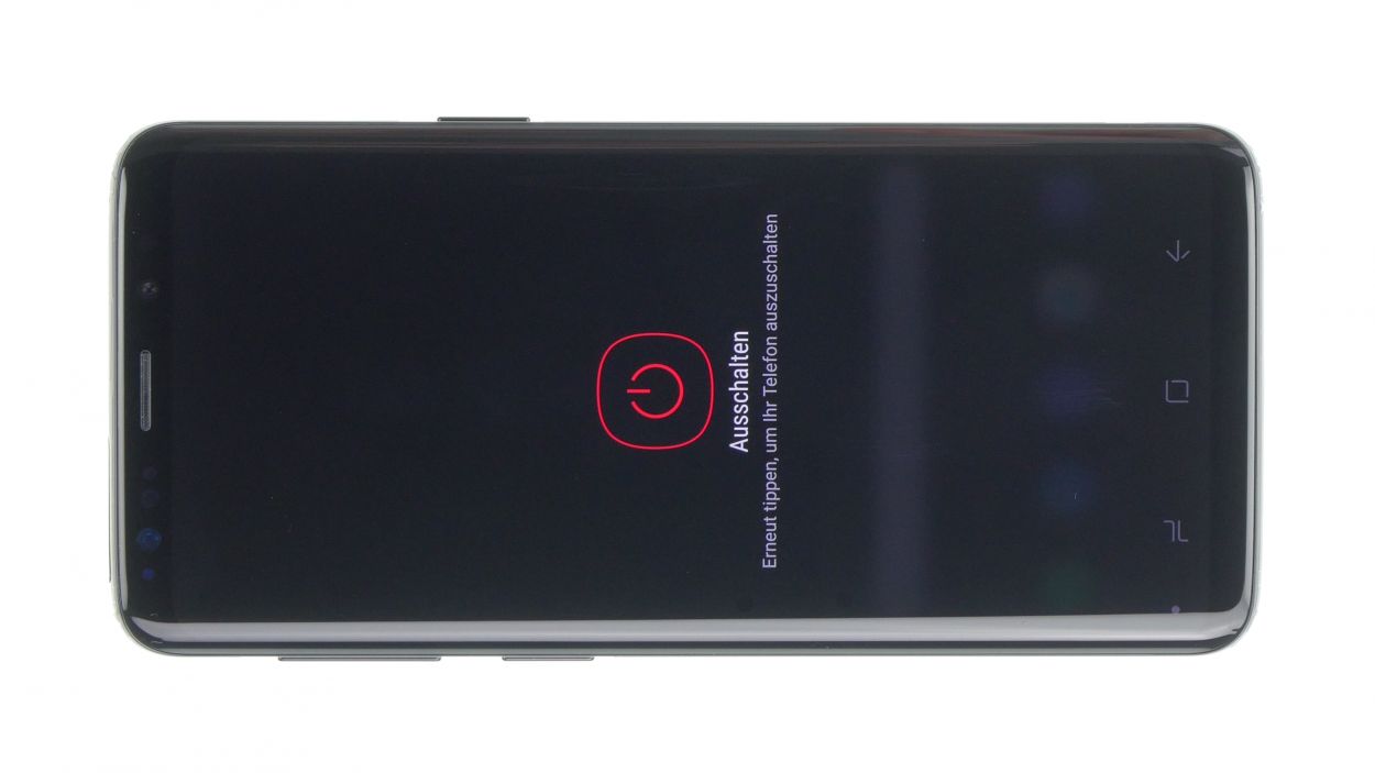
– First things first, let’s give your device a little break! Press and hold that power button until you see the ‘Power off’ option pop up.
– Now, just tap that option with your finger to confirm you want to power down your Galaxy Note 8. Sit tight and watch the screen go dark!
Step 2
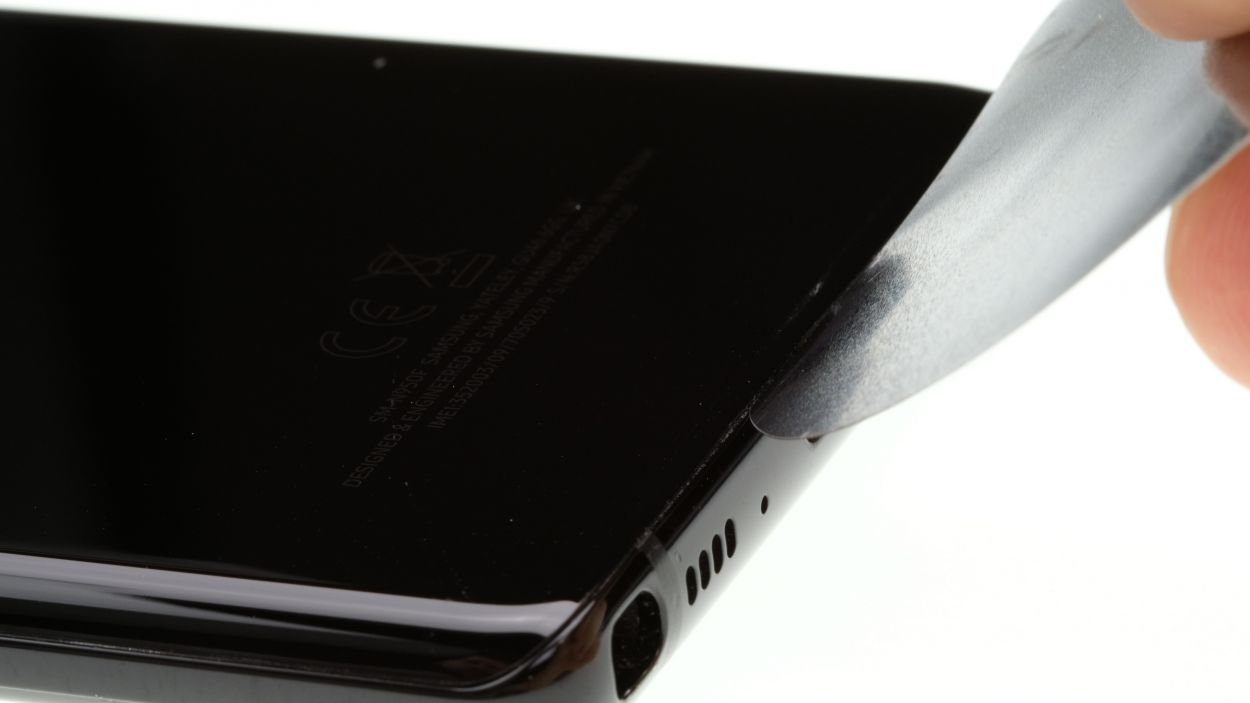
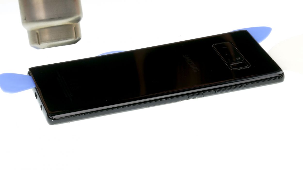
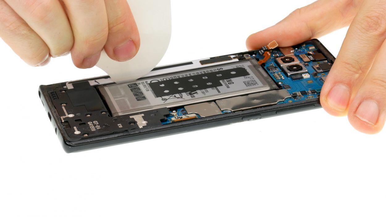
– Time to get your heat on! Soften that sticky glue by heating your device with some seriously hot air – we’re talkin’ 60 – 80°C, baby! You should still be able to handle your device without it being too toasty.
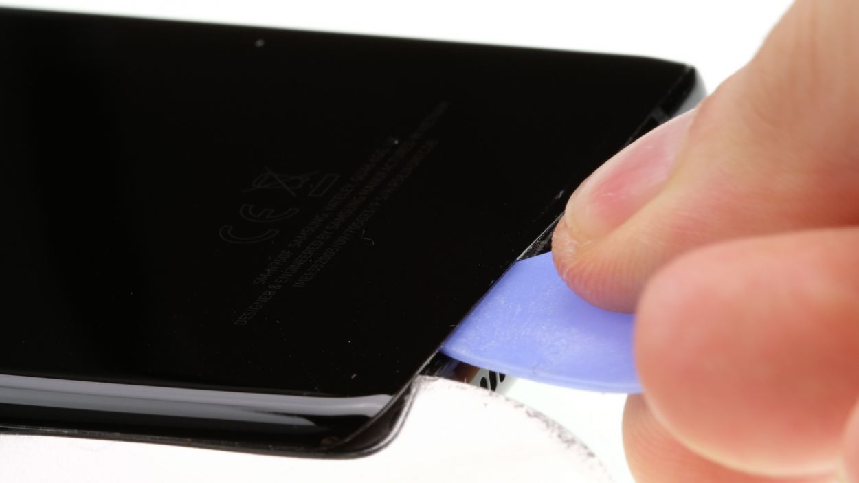
– Kickstart the process with a flat and flexible tool like the iPlastix or iFlex. Don’t forget to pick (heh) up the necessary tools, including some picks to get the back cover unstuck all around. If you need help, you can always schedule a repair.
Be extra careful, the back cover can break very easily. If necessary, apply the heat several times and try again. Removing the back cover might take half an hour. Take a little more time and work carefully to make sure you don’t break anything.
The iPlastix is made of plastic, so it won’t scratch the device. On the other hand, it’s very soft and tricky to insert.
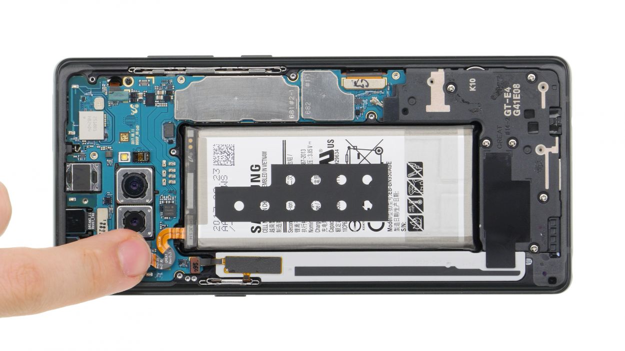
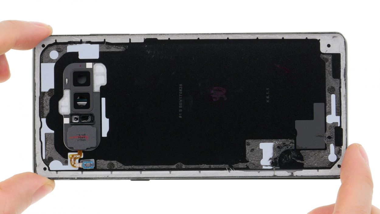
Step 3
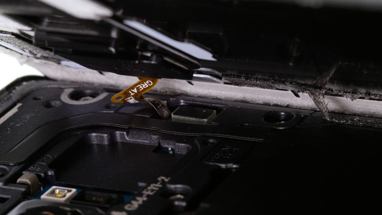
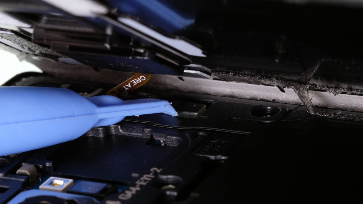
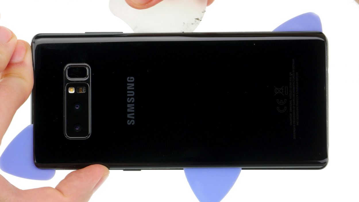
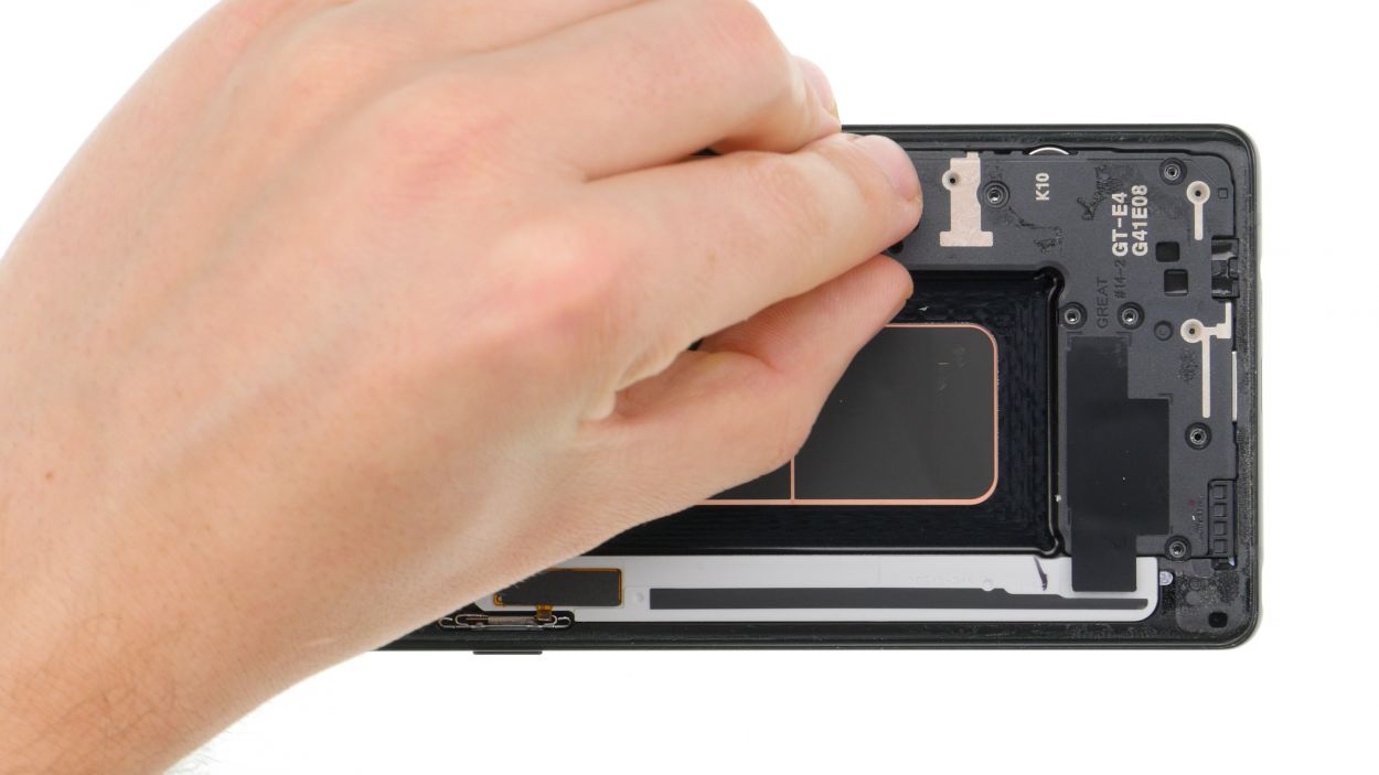
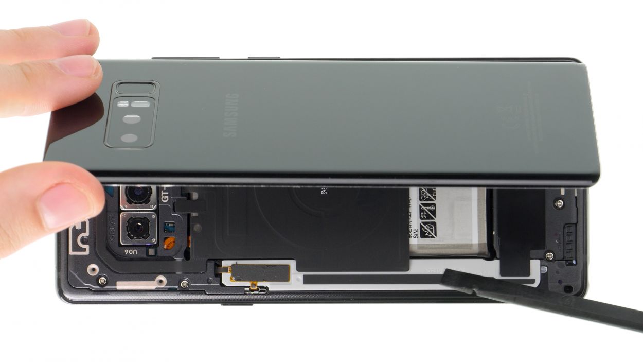
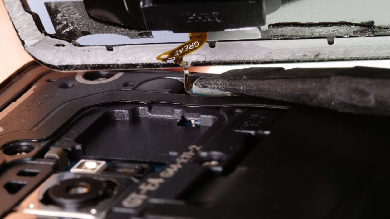
– Once you’ve popped off the back cover, gently lift it up and use your trusty spudger to disconnect the fingerprint sensor.
– Now, go ahead and fully remove the back cover and place it somewhere safe for later!
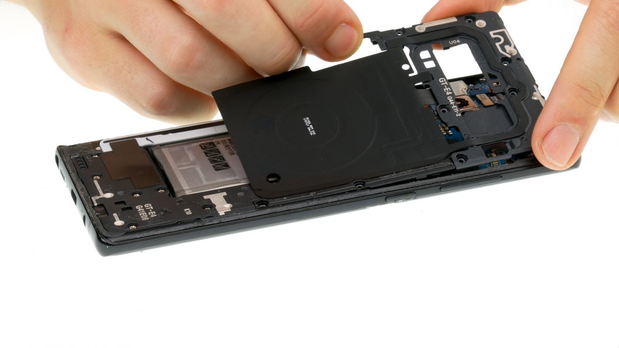
Step 4
10 × 3,7 mm Phillips
– First up, let’s tackle those screws holding the upper cover to the display. Time to get them out!
– Next, the cover is snugly latched onto the case, and the lower part of the antenna is just a tad glued. Grab a flat tool and gently slide it under the latches to pop them loose.
– Now, it’s time to say goodbye to the antenna. Remove it with care!
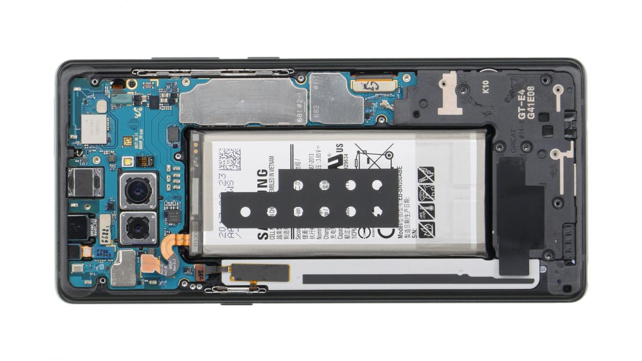
Step 5
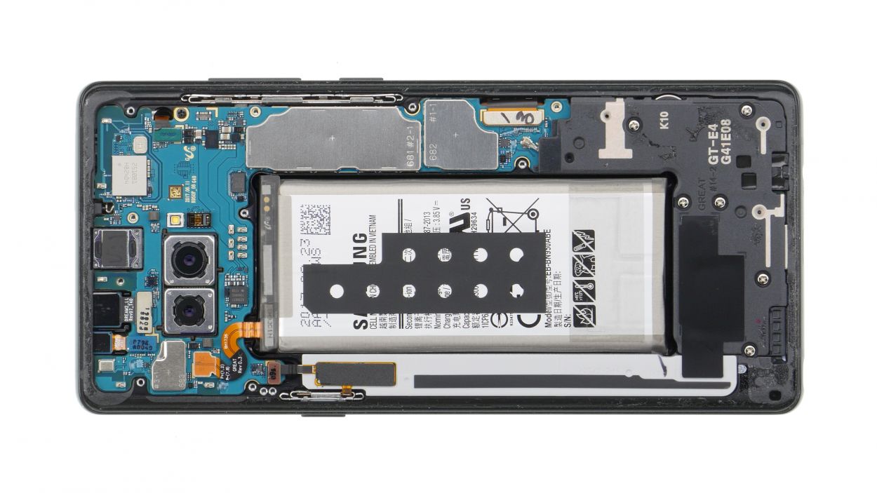
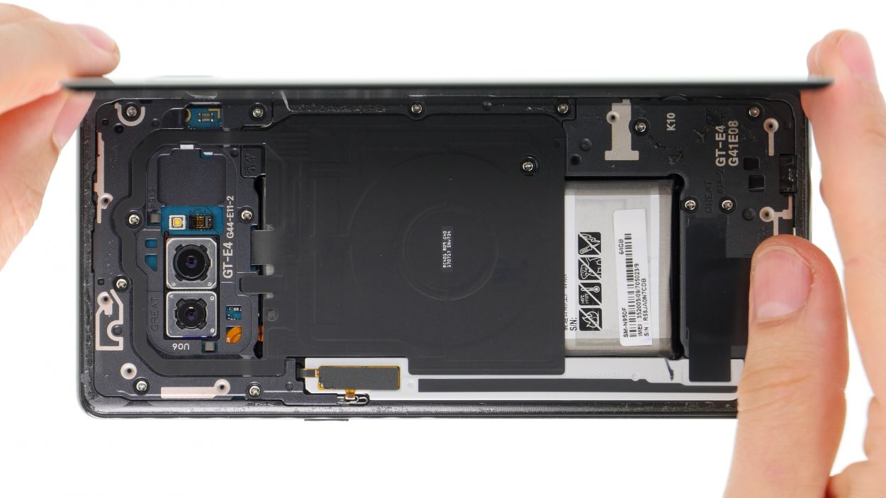
Battery connector
– Using the spudger, carefully disconnect the battery contact from the motherboard.
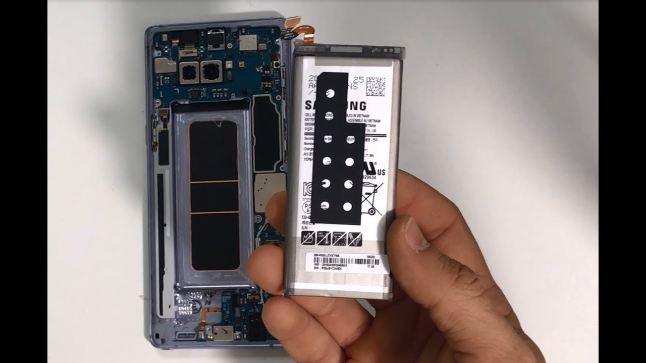
Step 6
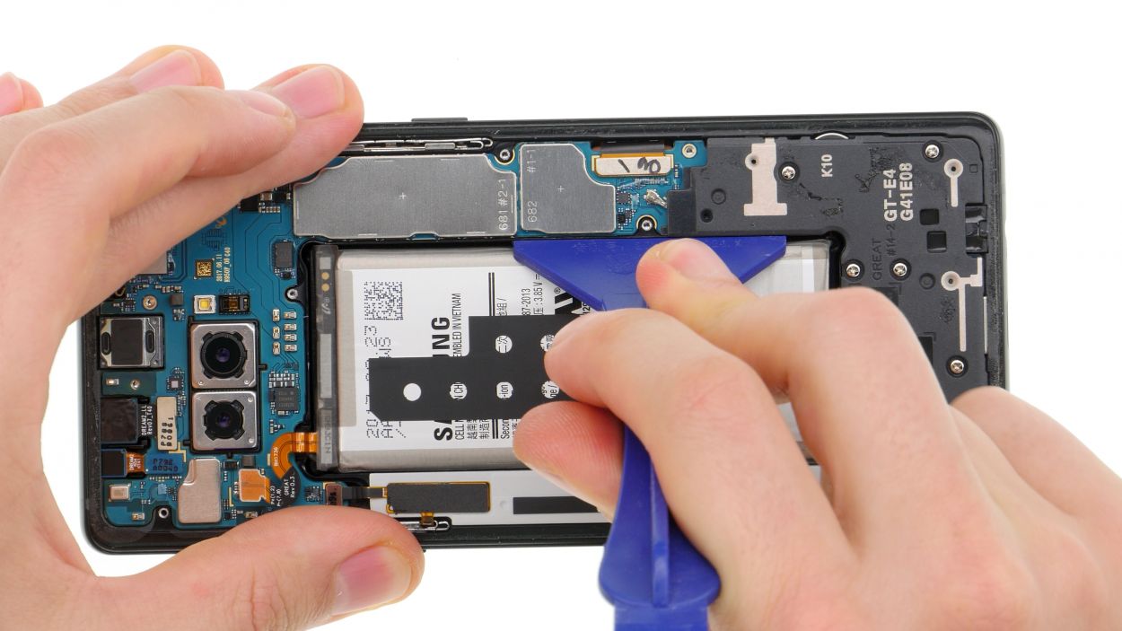
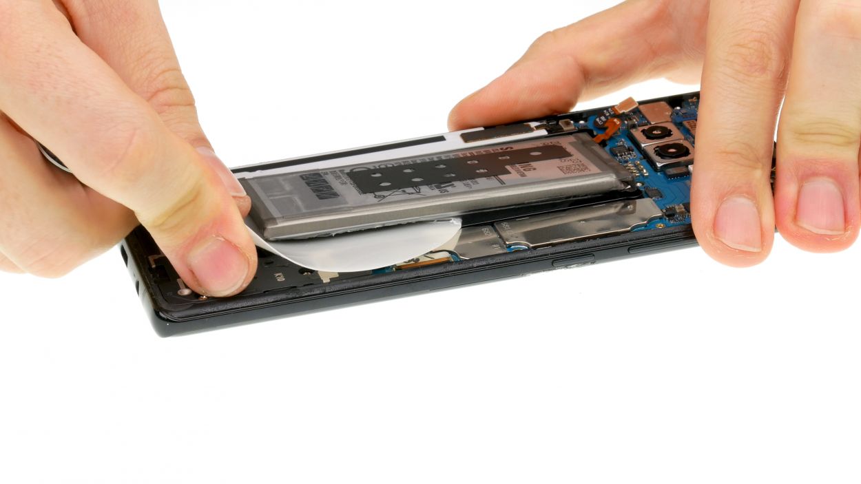
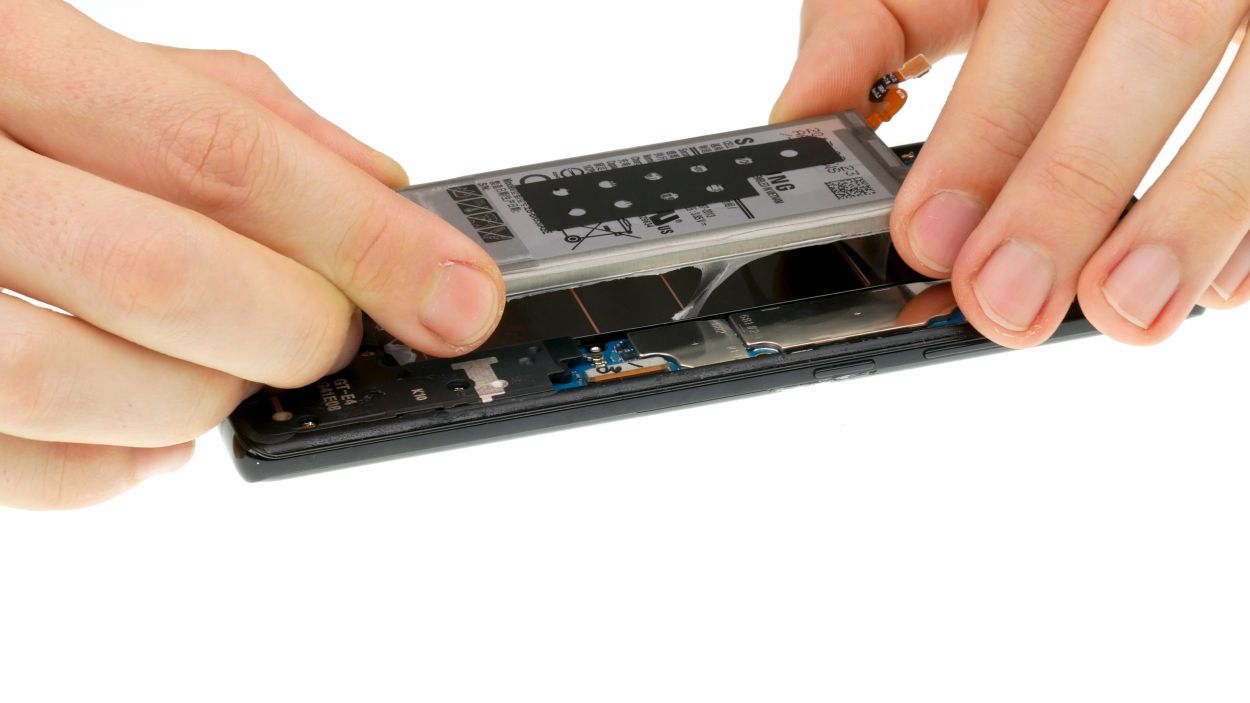
Hey there! Just a friendly reminder: keep that battery away from direct heat and give it some space—no bending allowed! Let’s keep things safe and sound!
Step 7
6 × 3,6 mm Phillips
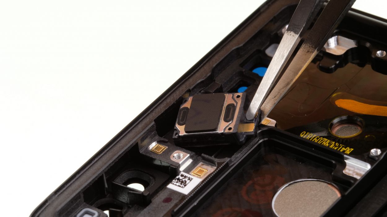
– Remove the screws that attach the speaker to the display and then remove it.
Step 8
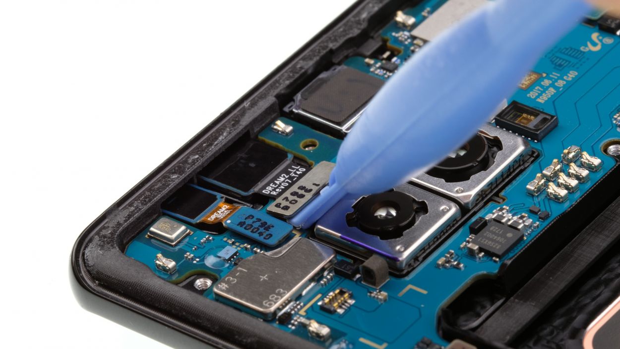
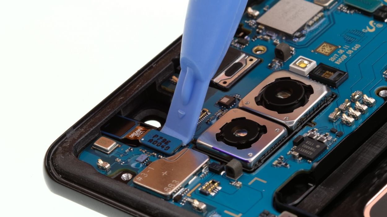
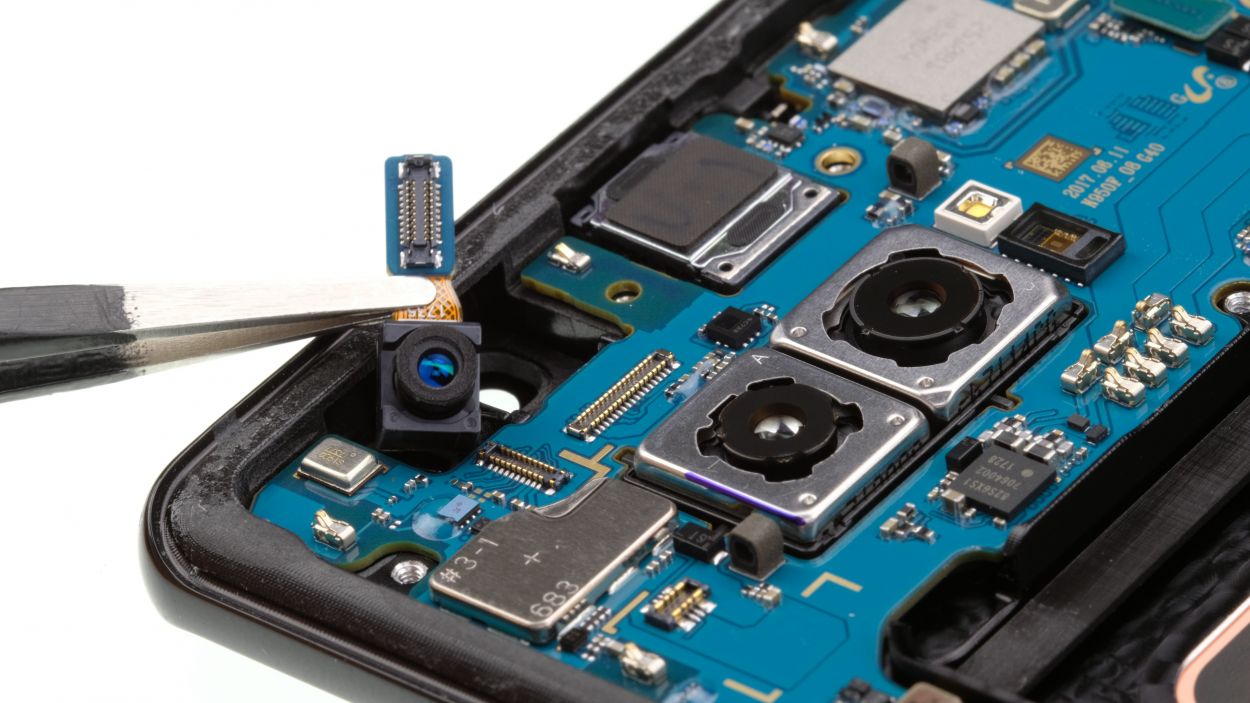
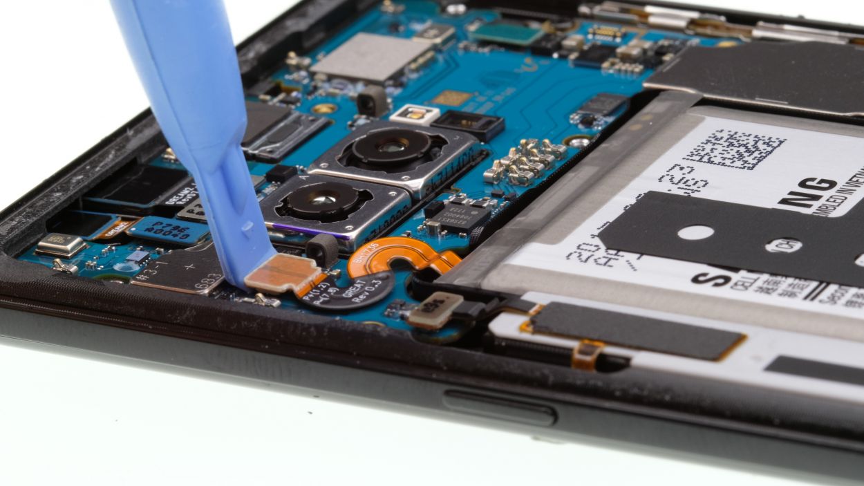
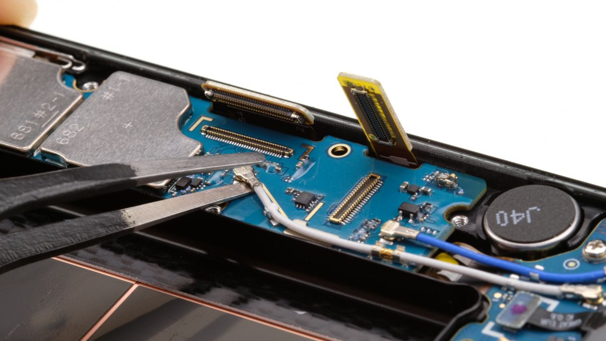
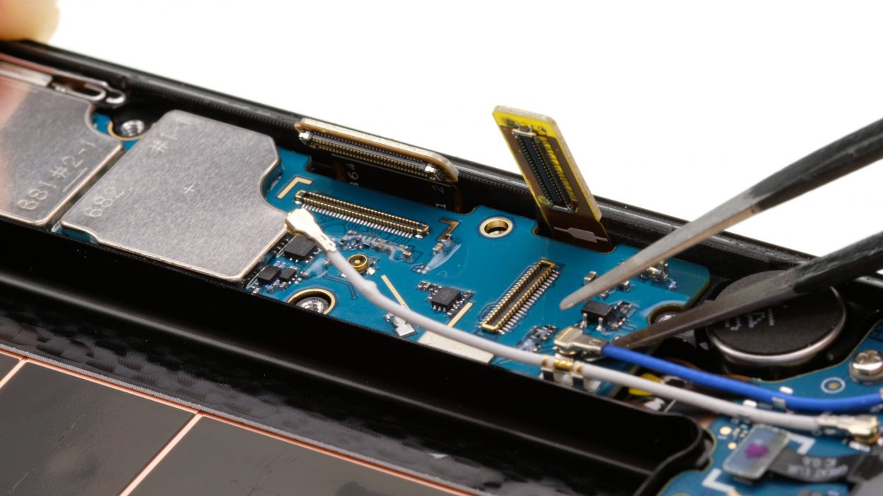
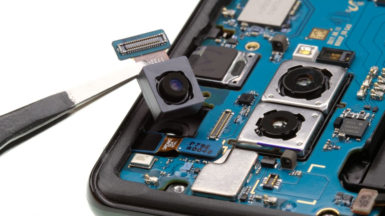
Camera connector
Sensor connector
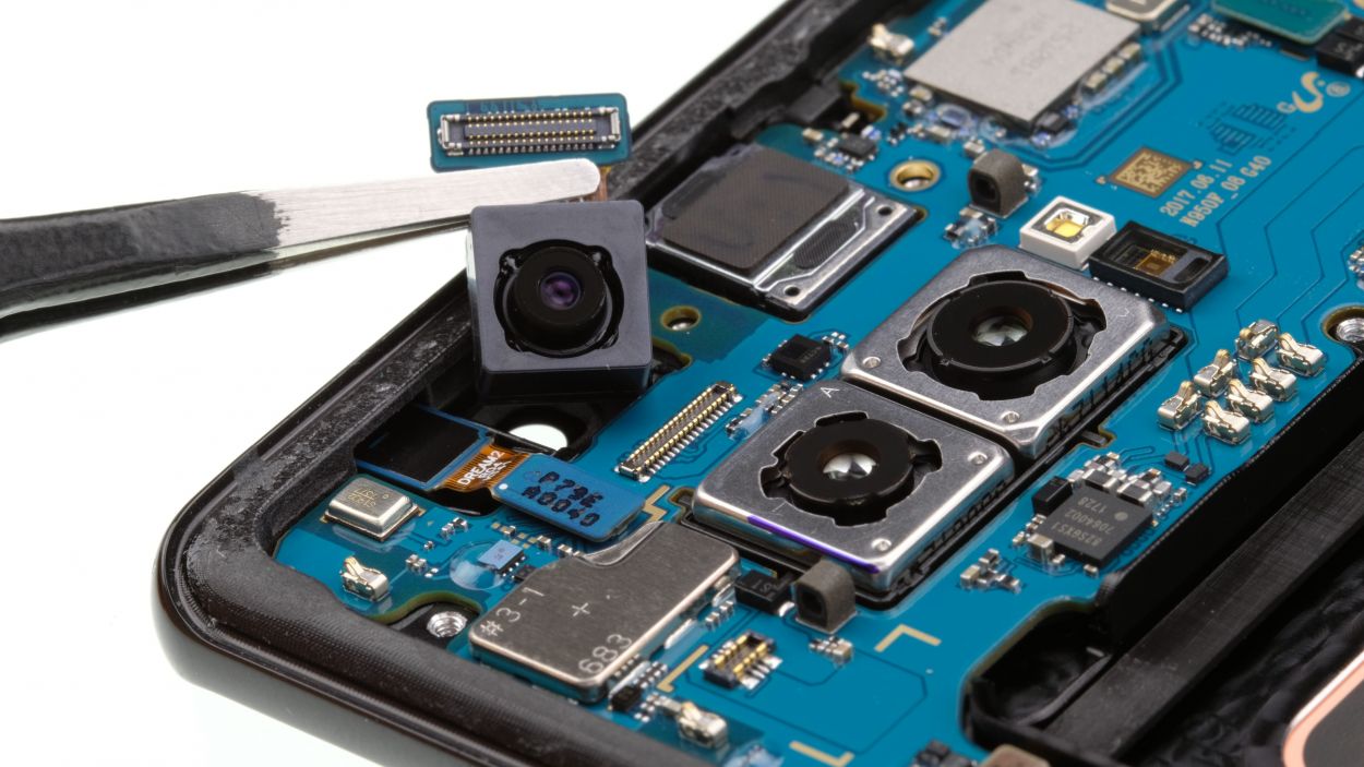
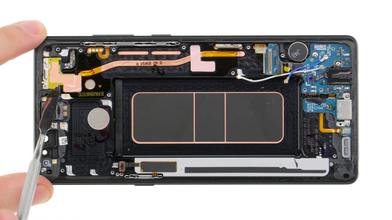
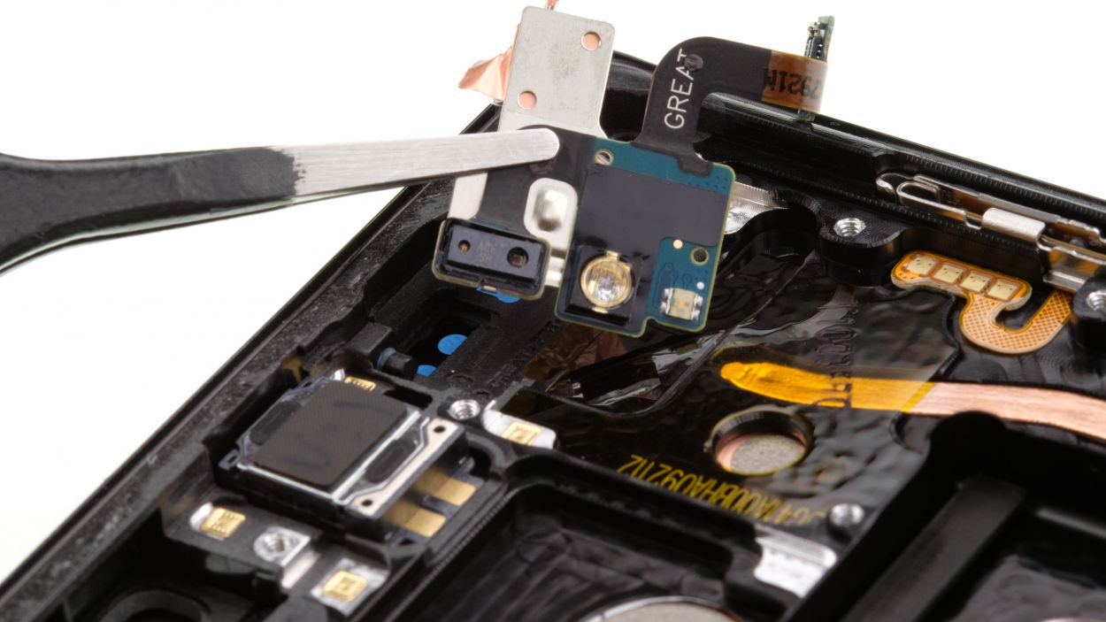
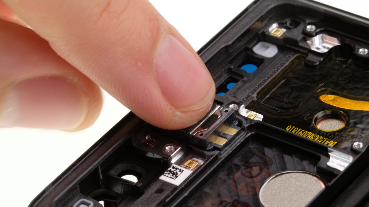
– First up, let’s disconnect those connectors for the front camera and the sensor. Easy peasy!
– Now, gently pry out the front camera and the sensor from the chassis and give them a little lift to remove them completely.
Step 9
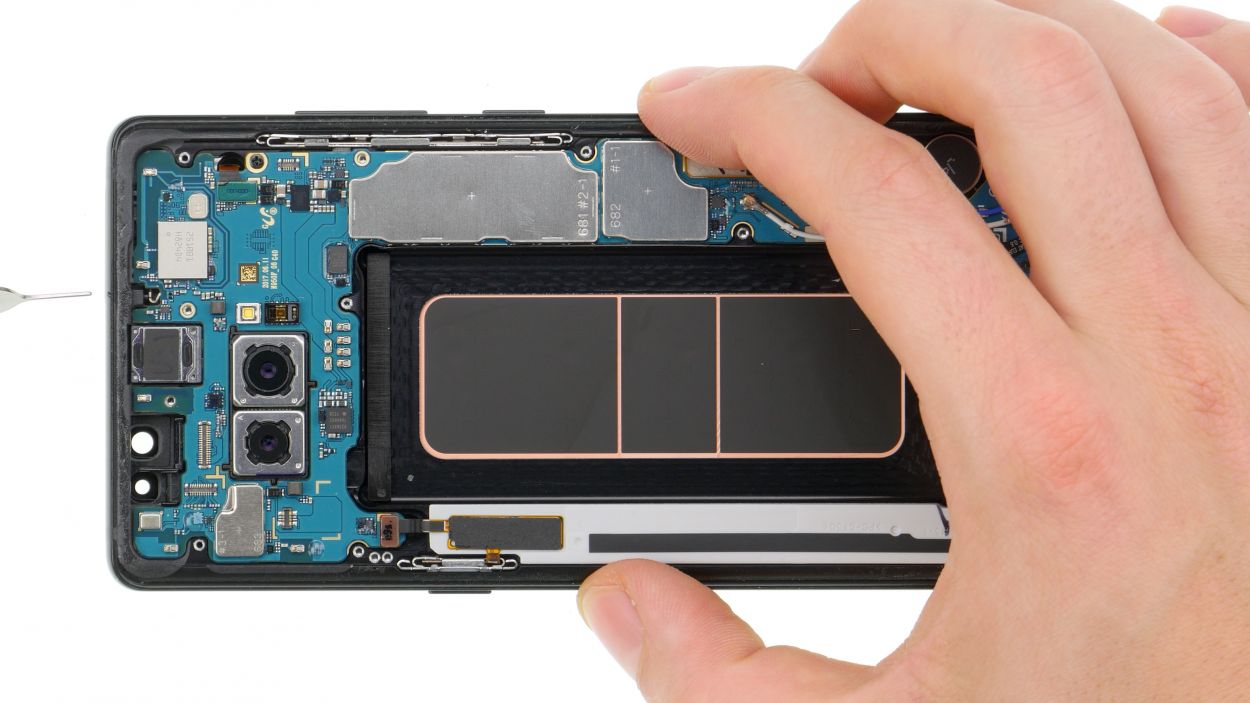
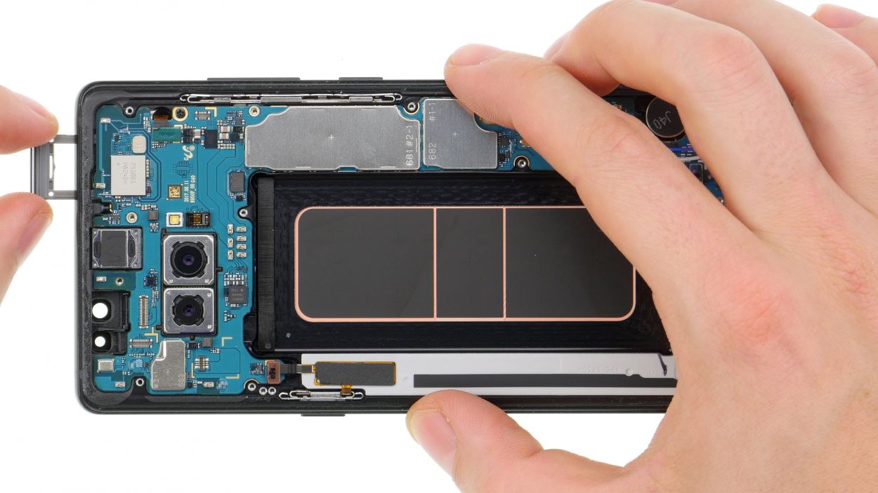
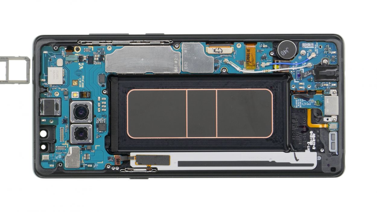
– Use the SIM tool to eject the SIM card tray from your device and then remove the tray with your fingers.
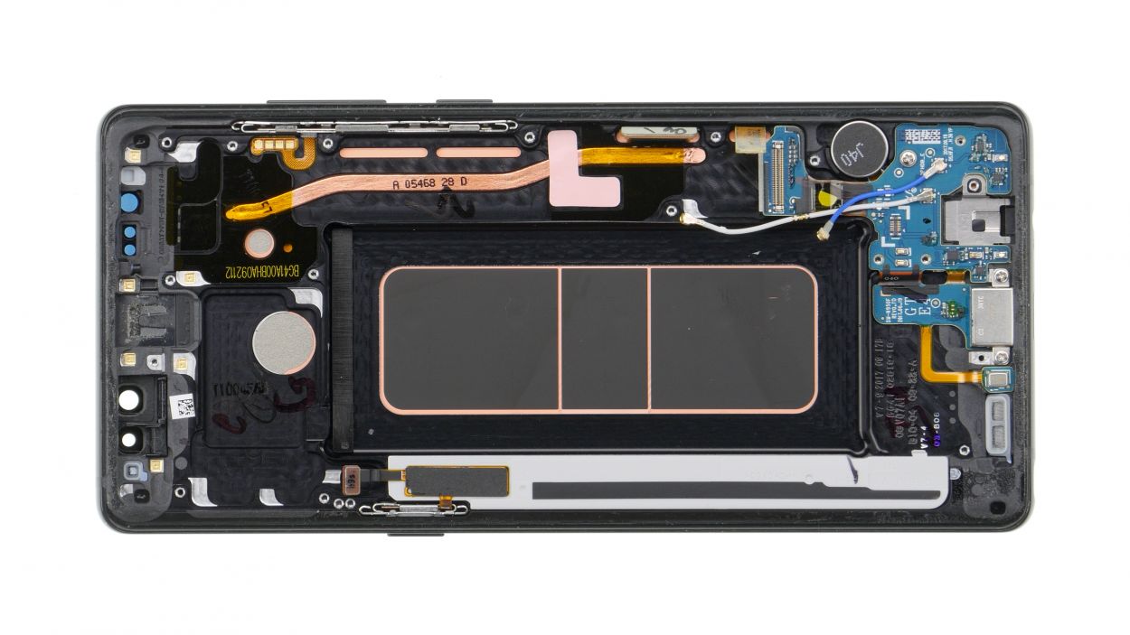
Step 10
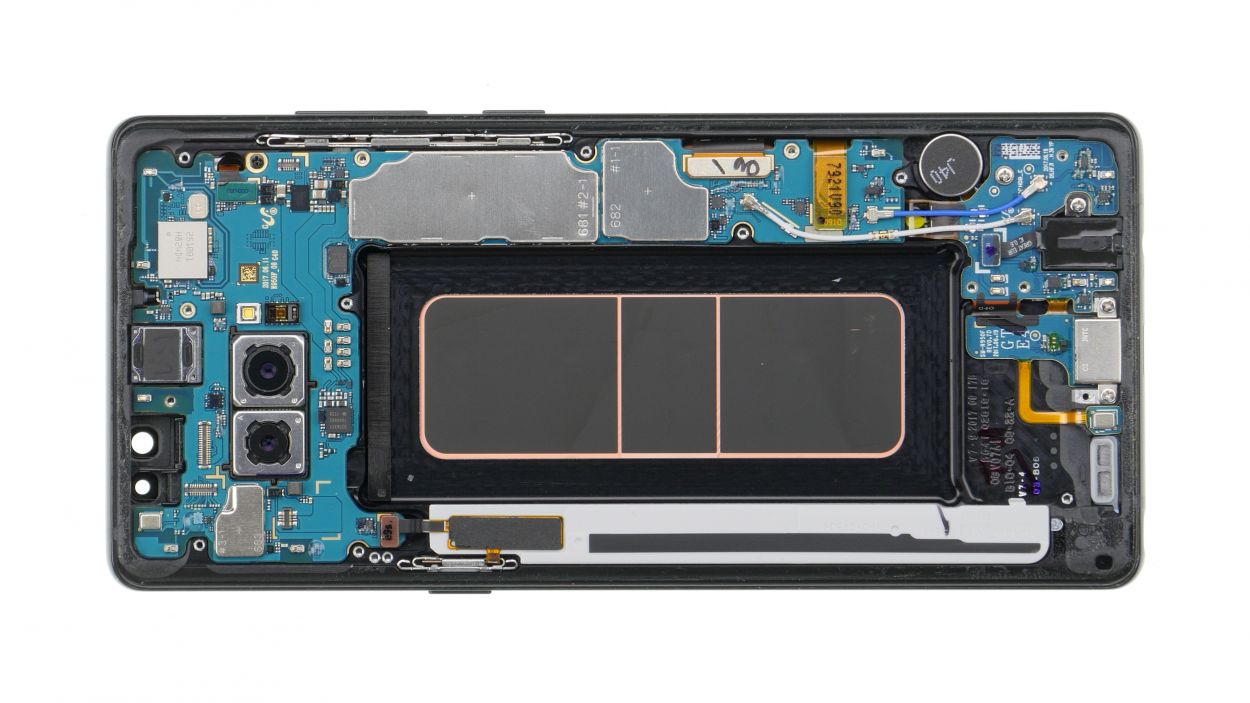

Connectors
1 × 2,9 mm Phillips
There’s a small plastic pin in the opening of the SIM tray. Make sure it doesn’t fall out.
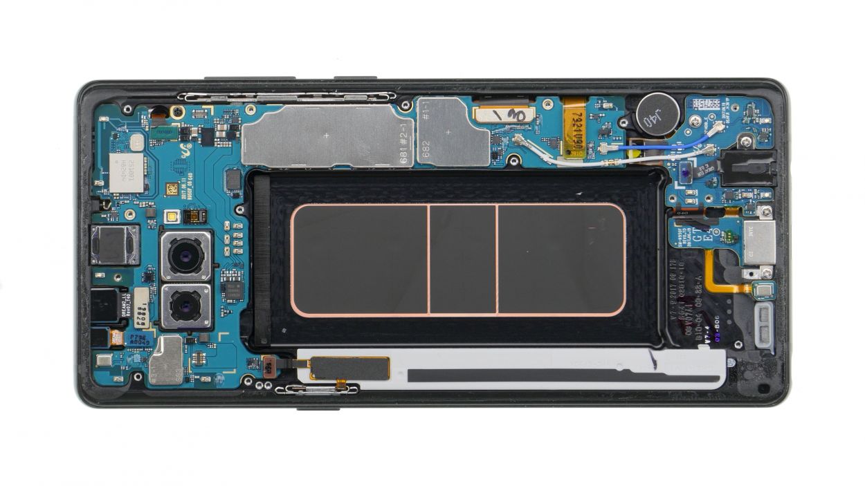
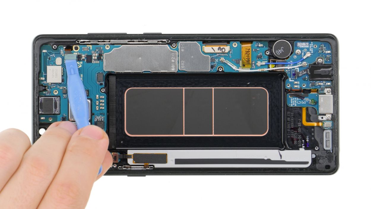
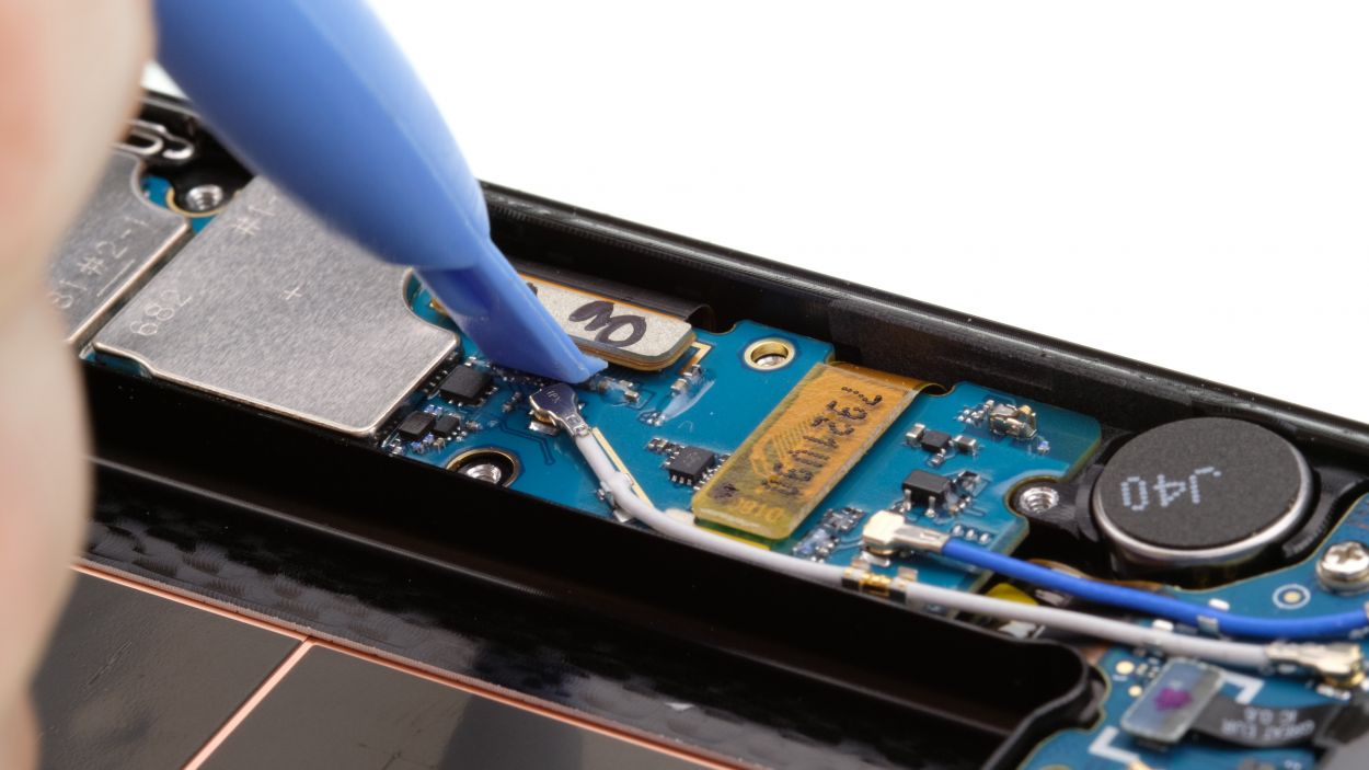
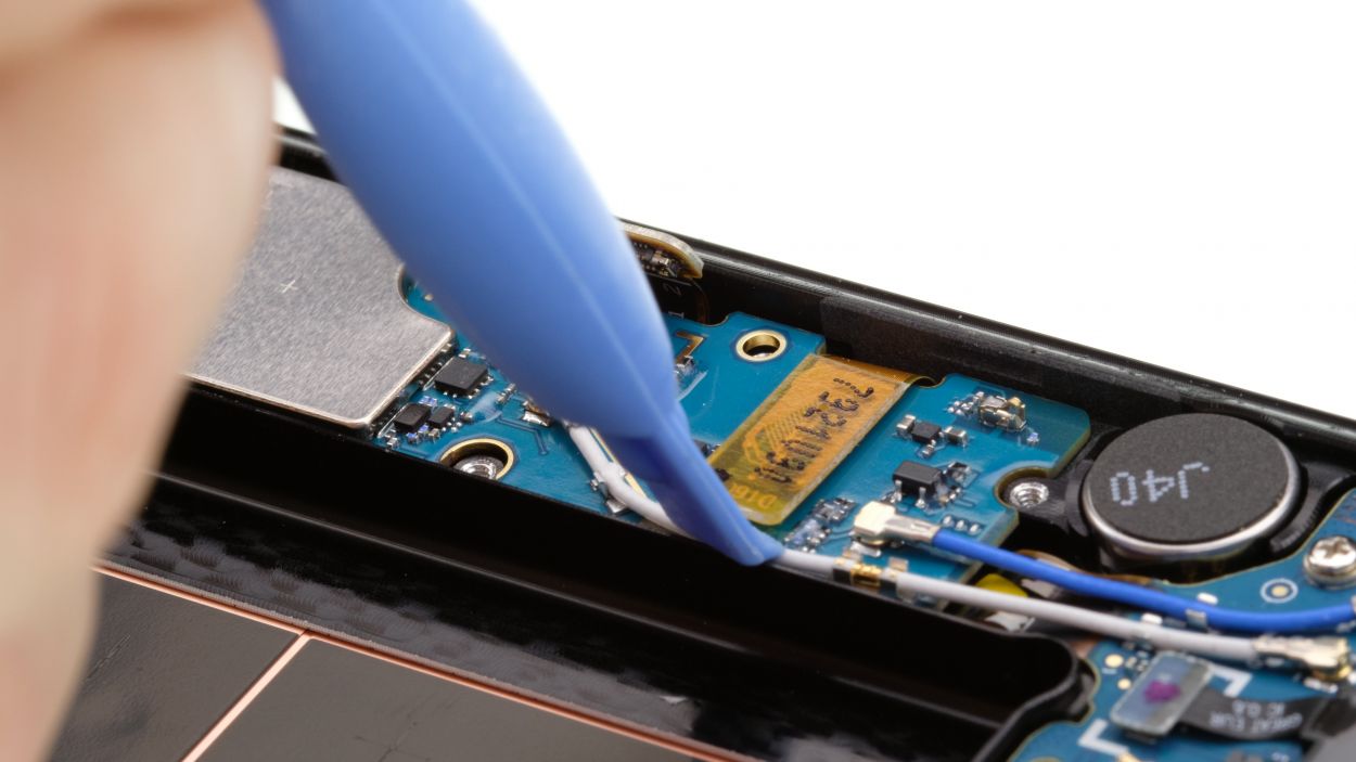
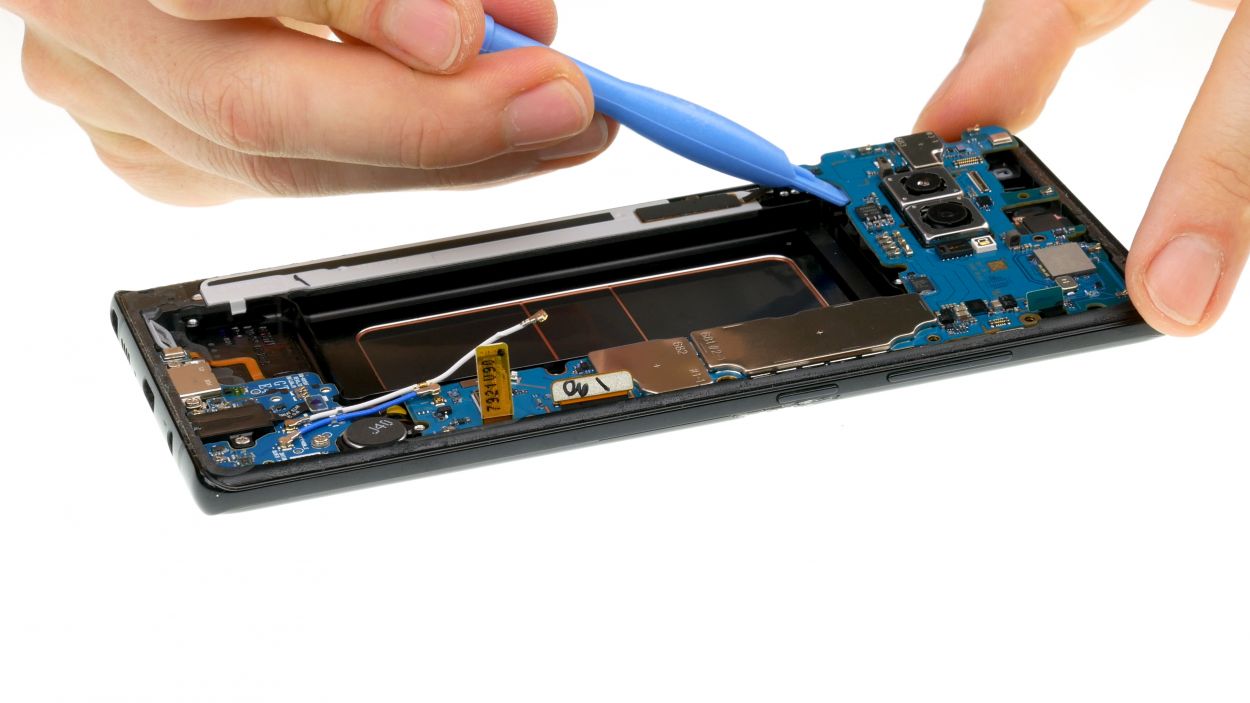
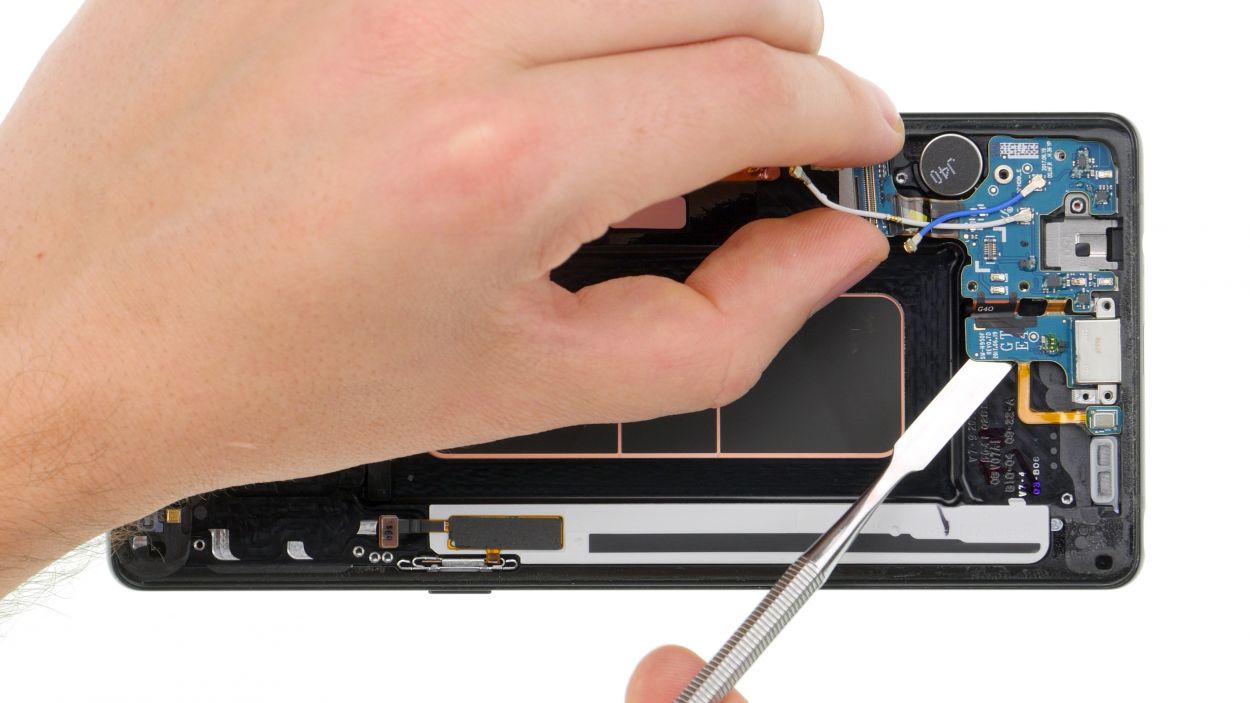
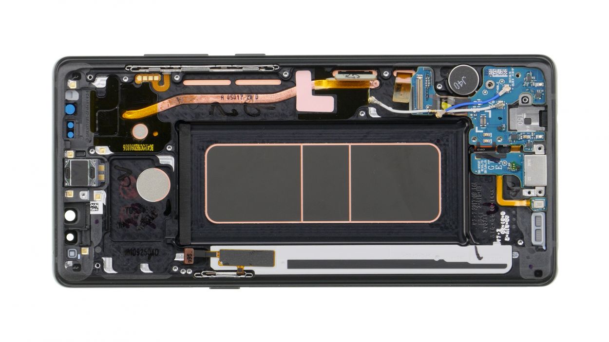
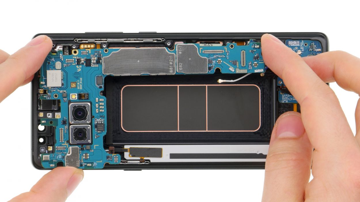
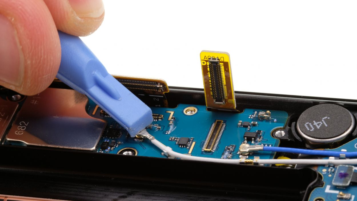
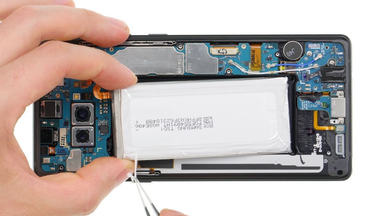
– Grab your trusty spudger and gently disconnect the highlighted contacts from the mainboard. Easy peasy!
– Next up, let’s get rid of that marked screw. You got this!
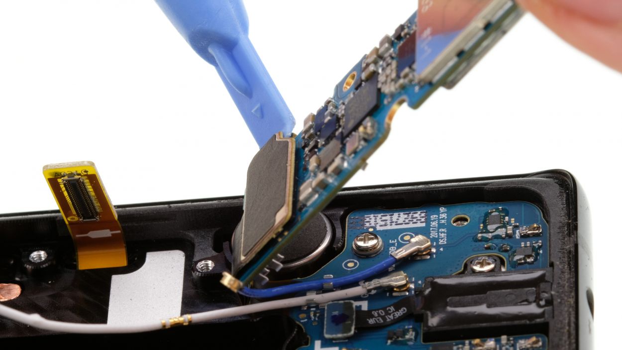
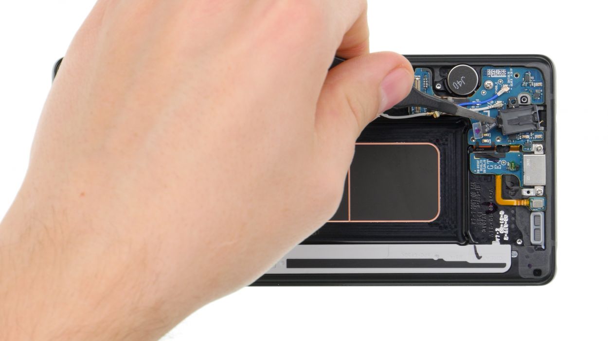
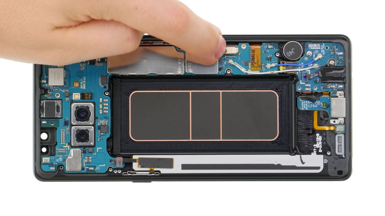
– Now, with a little care, lift the motherboard out. Just be sure it doesn’t snag on any connectors you’ve already unplugged.
– Don’t forget, the USB port is still hanging out at the back of the board. Once you’ve lifted it, use your spudger to disconnect that contact too.
– Finally, find a cozy spot to set the board aside and keep it safe. You’re doing great!
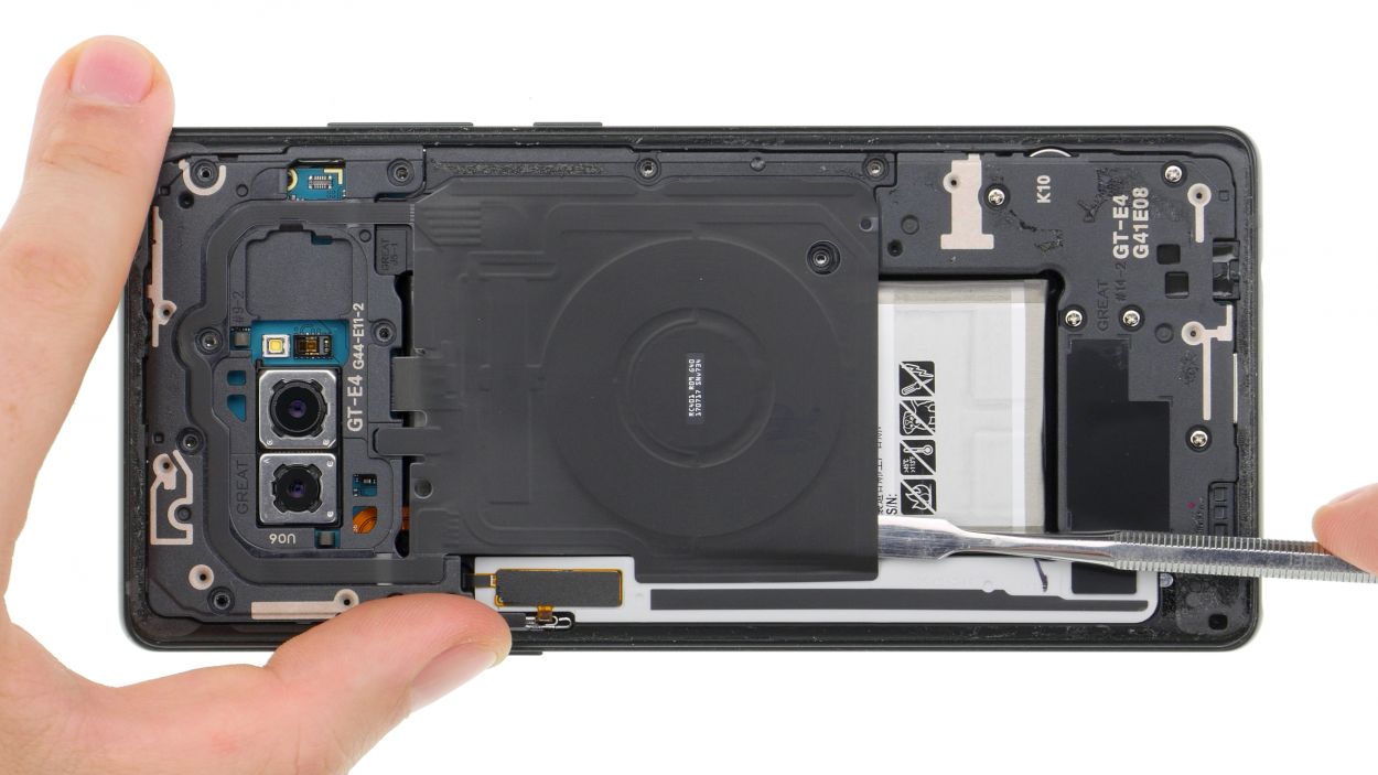
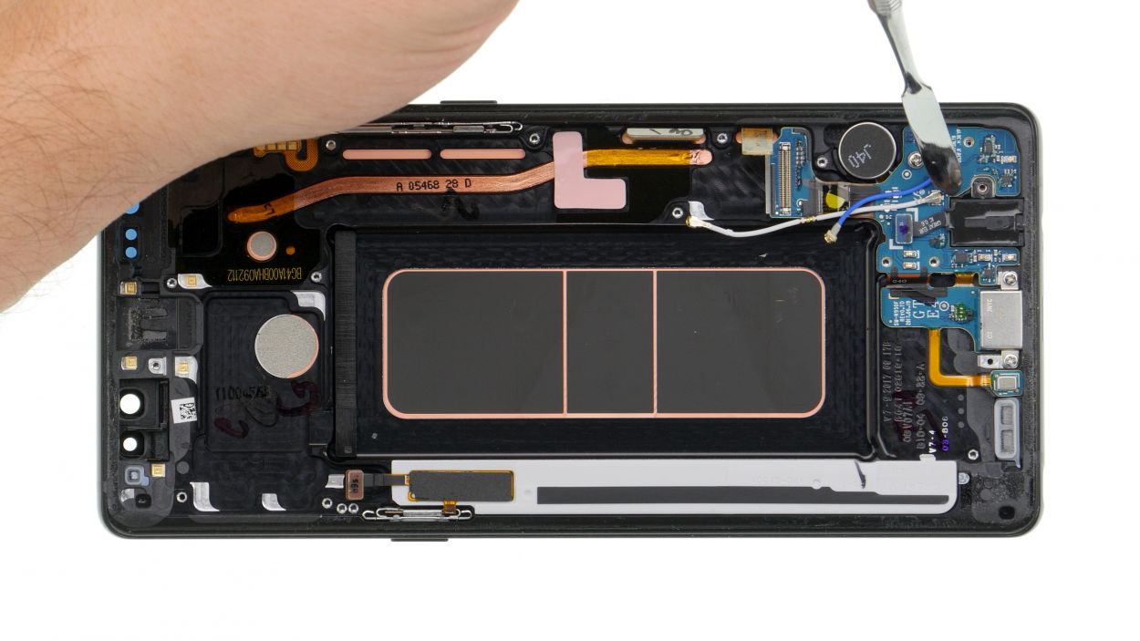
Step 12
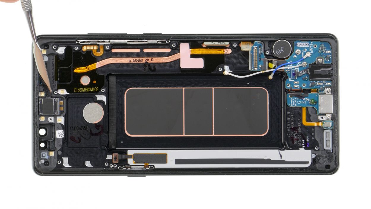
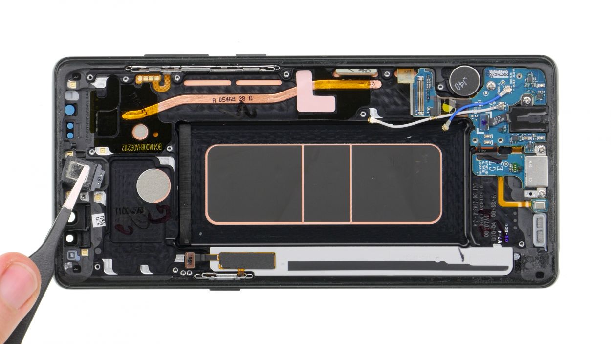
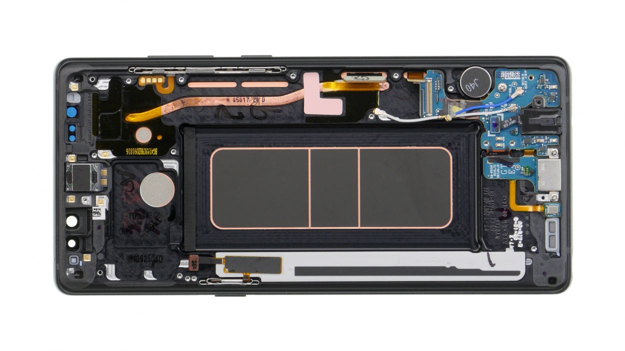
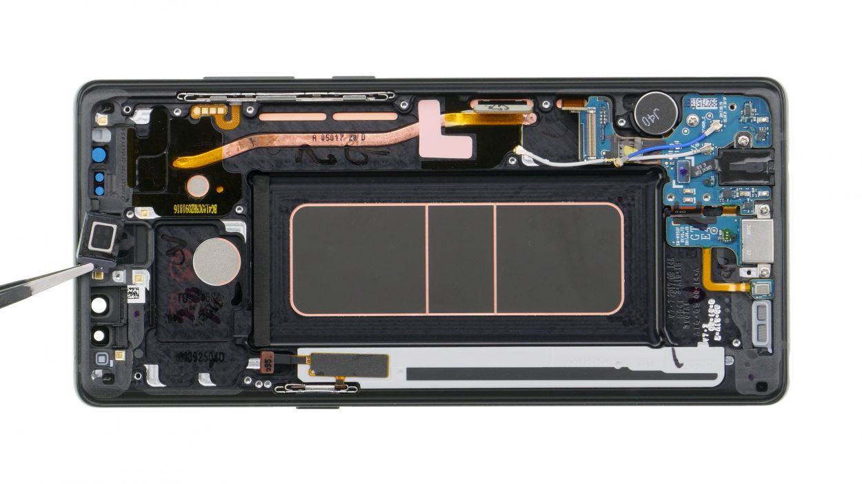
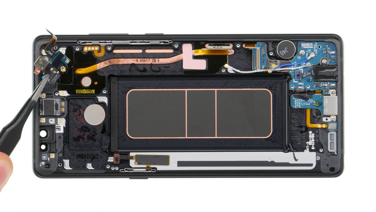
– The earpiece is glued to the enclosure. Carefully detach it with a flat tool like the steel spatula.
Step 13
1 × 3,5 mm Phillips
Audio connector
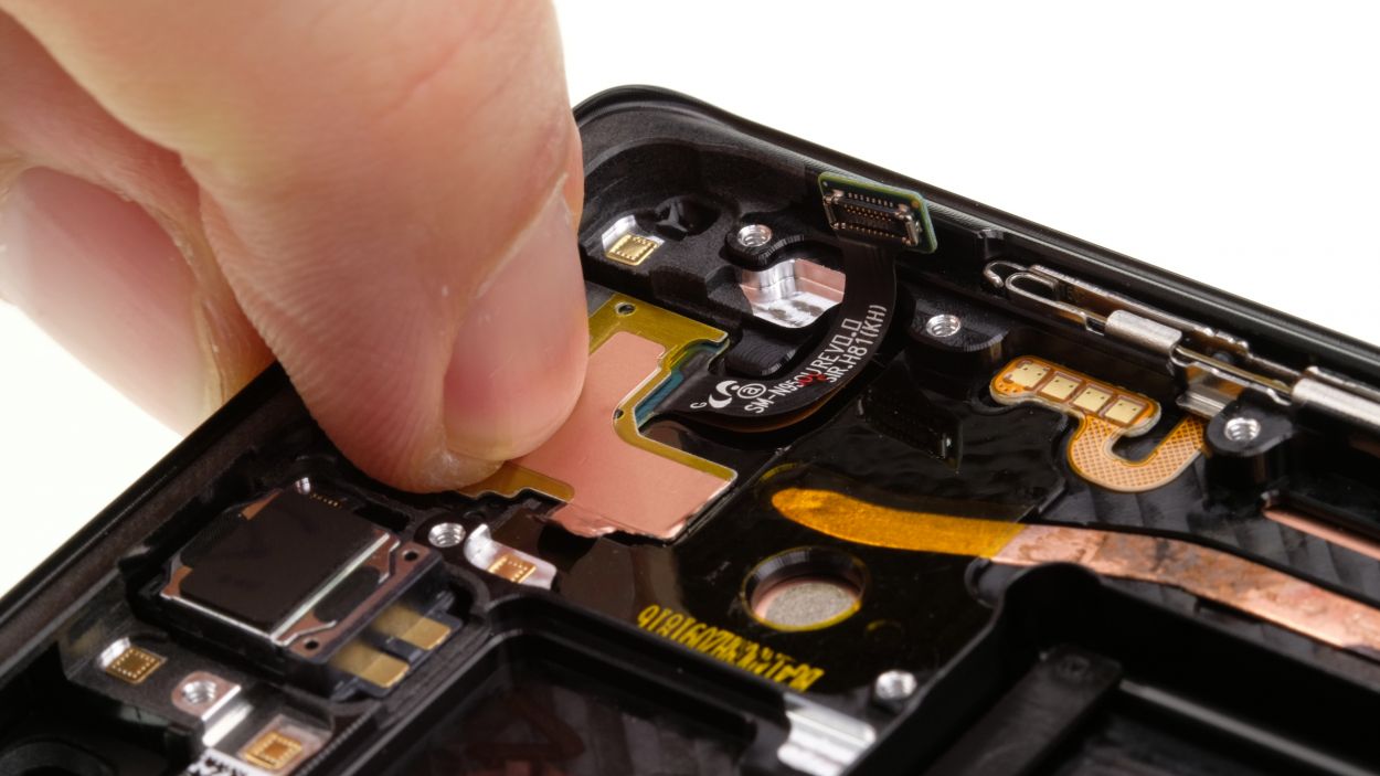
– Time to get your screwdriver out! Start by unscrewing the little screw that’s keeping the jack snug in its spot.
– Next up, let’s disconnect the headphone jack’s contact from the PCB. Grab your trusty spudger and gently pry that contact out of the socket like a pro.
– Finally, it’s time to say goodbye to the headphone jack! Carefully remove it from the enclosure and make way for the new.
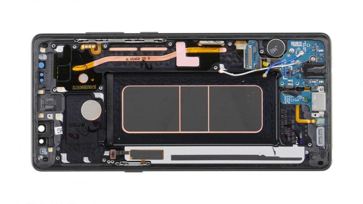
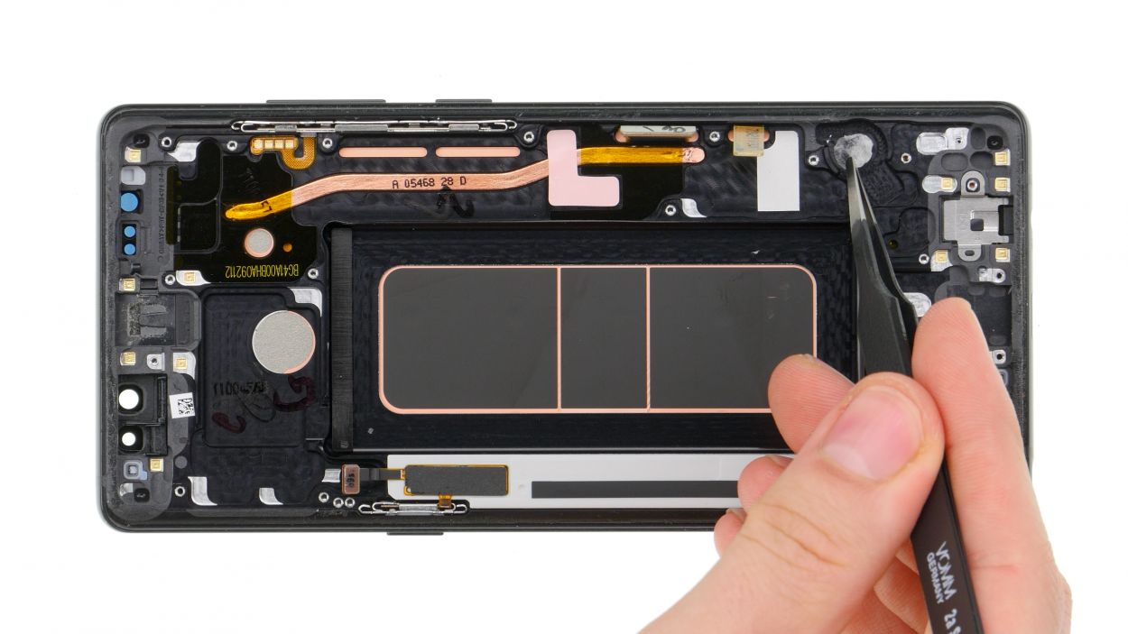
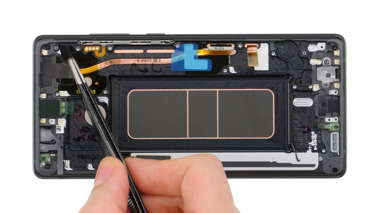
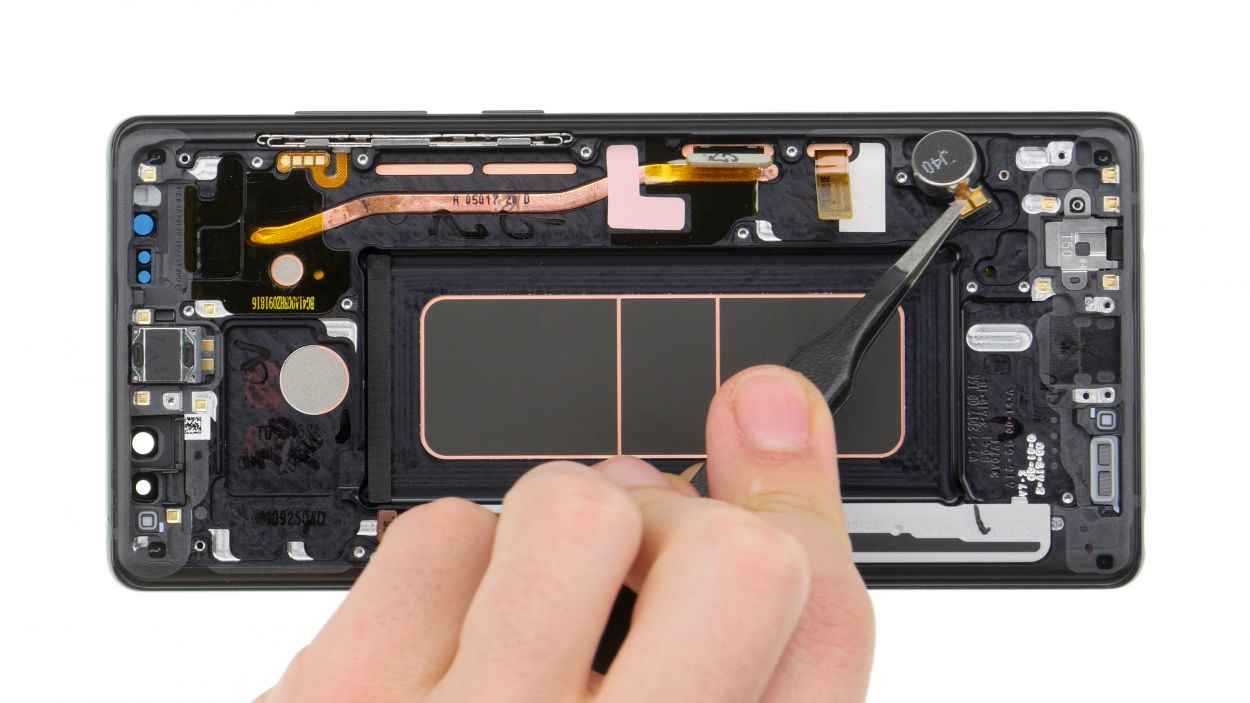
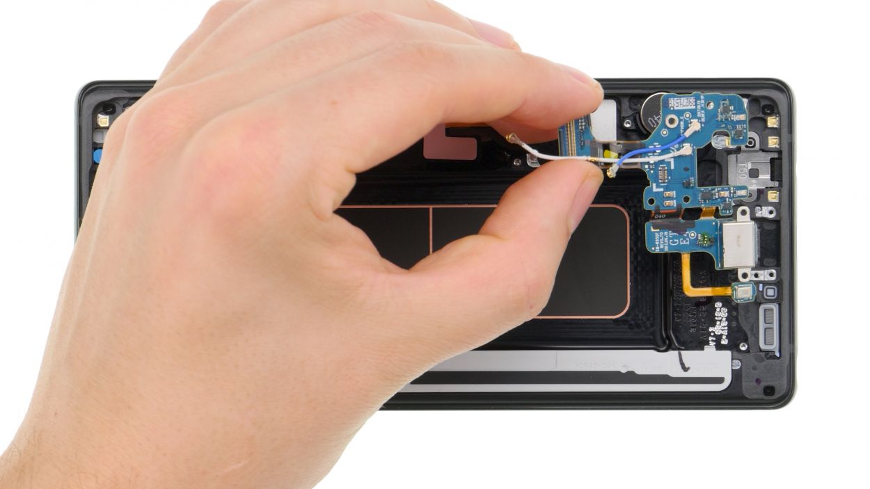
Step 14
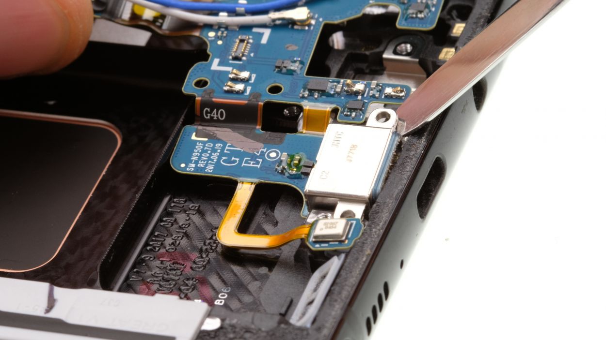
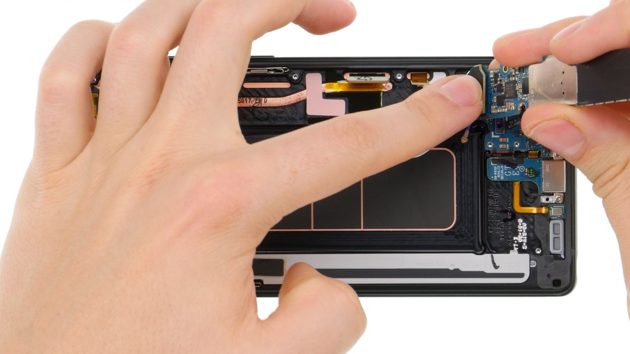
3 × 3,5 mm Phillips
– Let’s get started by taking out those marked screws!
– Next up, gently detach the two antenna cables from their guide.
– Now, grab your trusty spudger and carefully pry out the board to remove it completely.
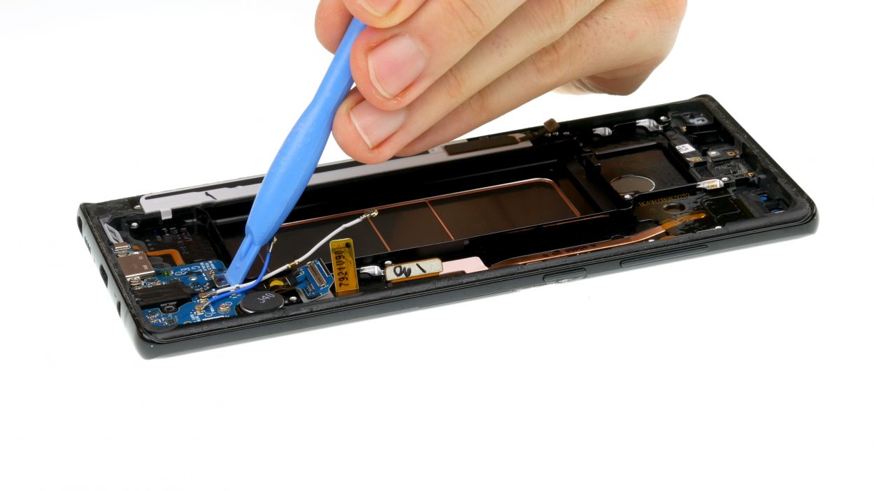
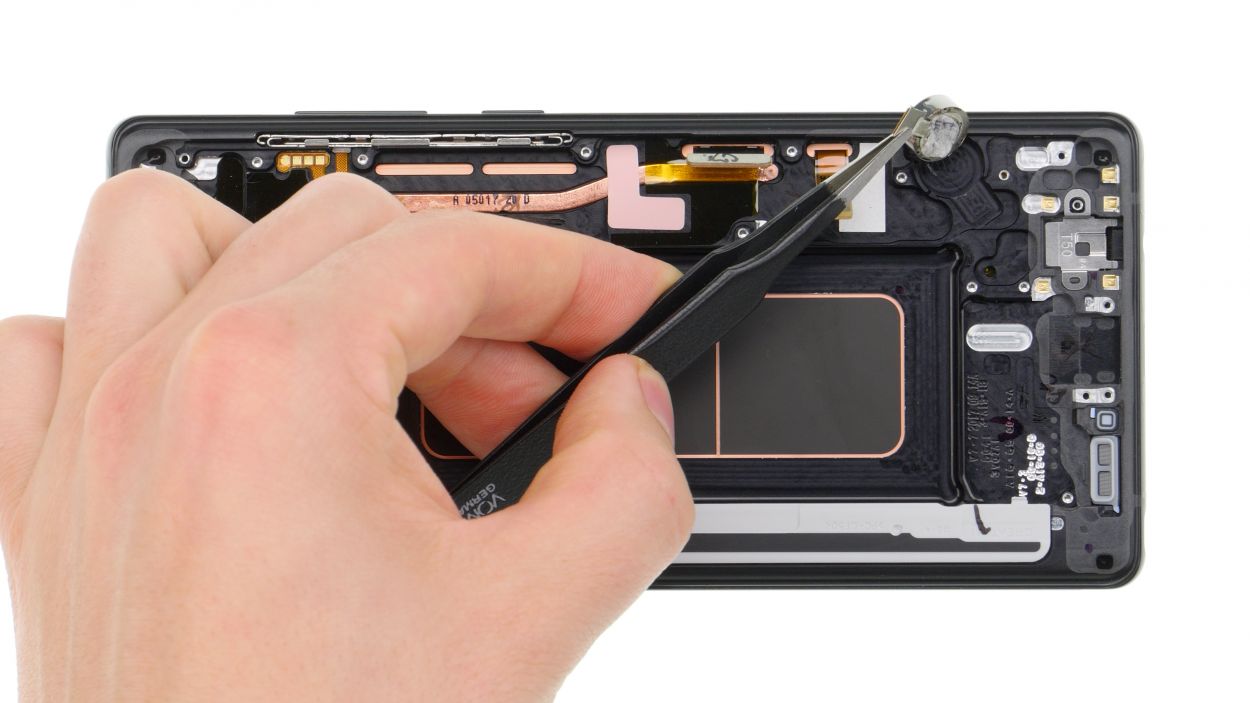
Step 15
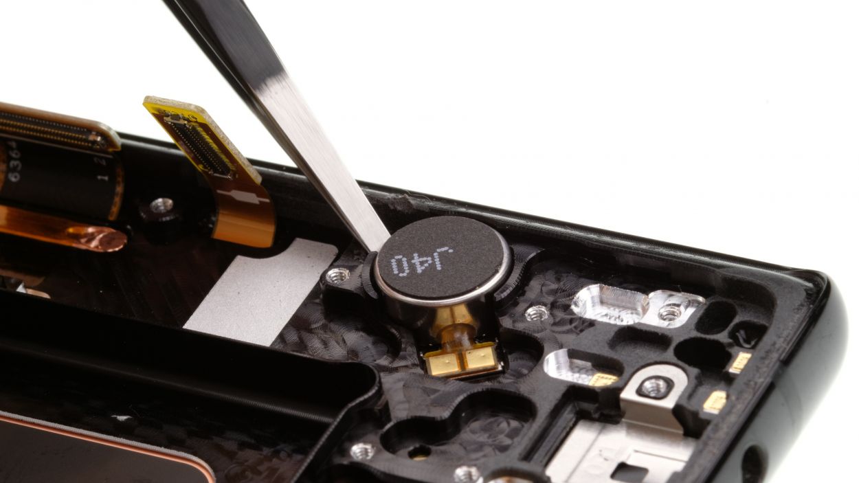
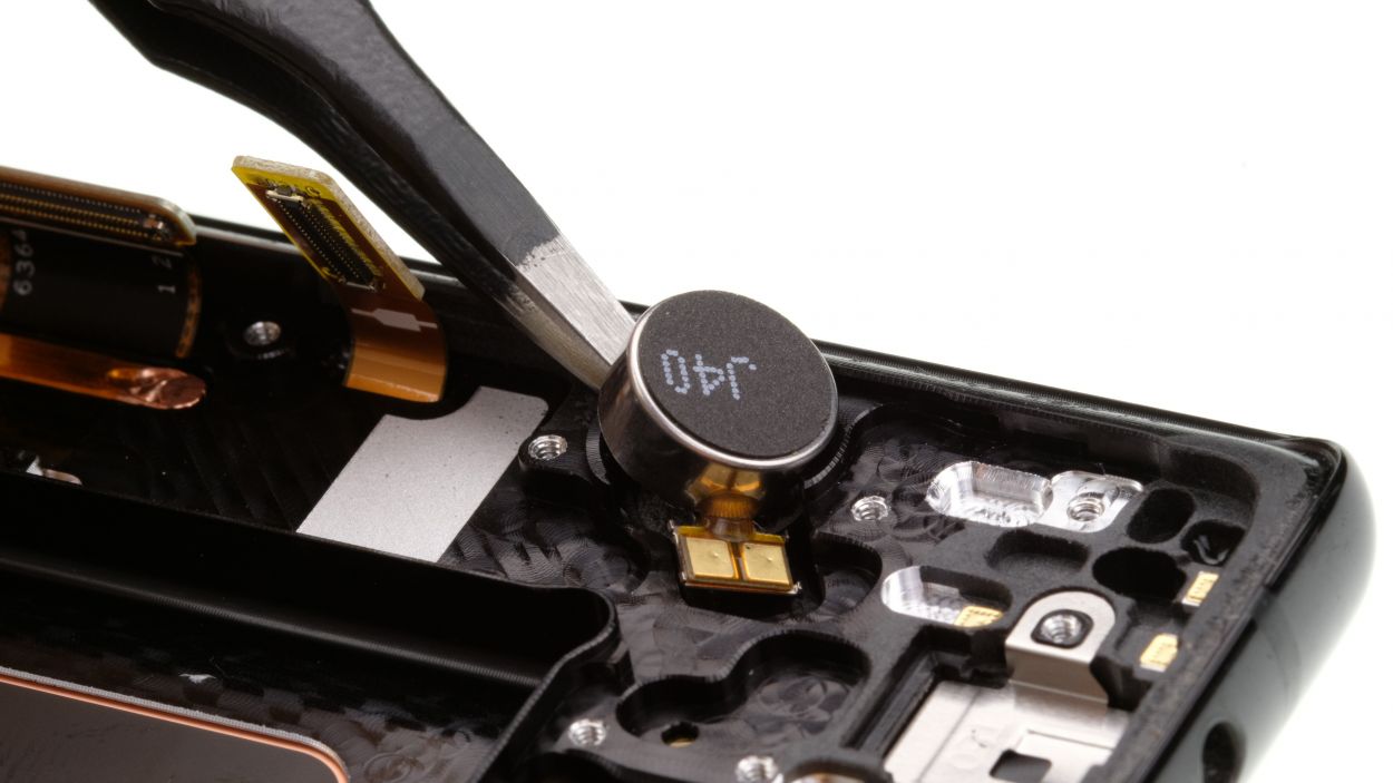
– That vibration motor’s stuck fast! Gently wiggle your tool between the motor and the enclosure to free it.
– Time to give that motor its freedom! Pop it out.
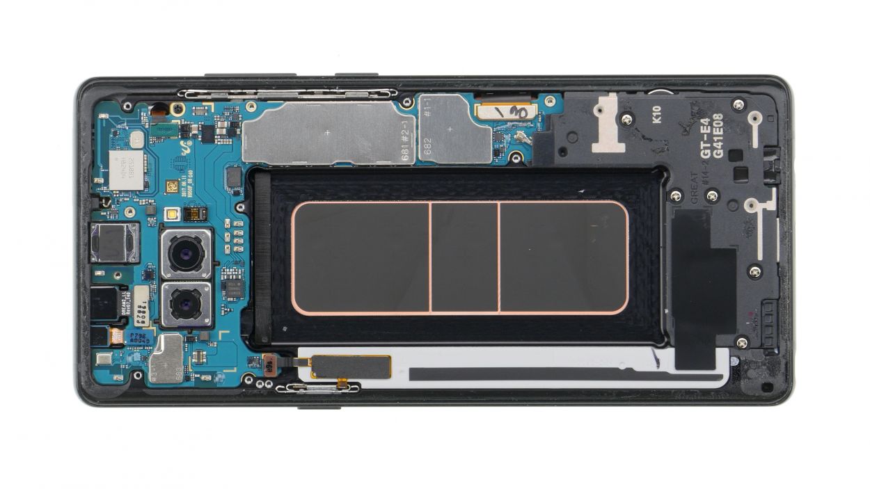
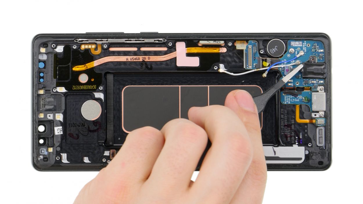
Step 16
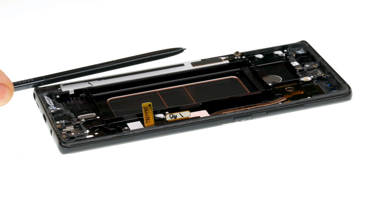
Protective film
– Before diving into assembly, make sure to peel off the transparent protective film covering all the adhesive surfaces and thermal pads in the new display’s enclosure. It’s like unwrapping a gift, but way more exciting!
– Next up, grab the S-Pen from the old display. It’s time to give it a new home!
Step 17
– Put the vibration motor in the little round opening on the left side of the enclosure.
– Use your fingers to press the motor firmly into place.
Step 18
3 × 3,5 mm Phillips
Get that board snug against the case! Make sure it’s all flush and happy. If you’re struggling, you can always schedule a repair
– It’s time to put that USB board back in its cozy little home!
Step 19
1 × 3,5 mm Phillips
Audio connector
– Slide that jack right into its cozy spot at the bottom edge of the enclosure.
– Now, connect the plug contact like a pro.
– Finally, secure it all in place with the right screw. You’re almost there!
Step 20
– Carefully place the earpiece back into its cozy little home.
– Give it a gentle press to help the glue do its magic and stick like a champ.
Step 21
– Insert the sensor cable in the corresponding recess in the upper edge of the enclosure.
– Press the sensor firmly with your finger so the glue will stick again.
Step 22
1 × 2,9 mm Phillips
Connectors
– First up, let’s get that USB board connected on the back of the main board. You’re doing great!
– Next, gently slide the board back into its cozy enclosure. Just a friendly reminder: keep an eye out for any cables or connectors that might want to sneak under the board.
– Now, it’s time to secure the motherboard with the designated screw. Tighten it up, but not too tight!
– Finally, reconnect those marked contacts to the board. You’re almost there!
Step 23
– Insert the SIM card tray back into your device. Make sure the tray is positioned properly.
Step 24

– Put the front camera and the sensor in the opening at the upper edge of the enclosure and reconnect the connectors.
Step 25
Step 26
6 × 3,6 mm Phillips
– First up, let’s place that speaker at the bottom of the enclosure.
– Give it a gentle press with your fingers until you hear that satisfying click as it settles in.
– Now, it’s time to put those marked screws back in their happy little homes.
Step 27

Battery connector
– Connect the battery to the motherboard. Gently press the contact onto the connection on the motherboard until you hear that satisfying click, letting you know it’s snug and secure.
Step 28

10 × 3,7 mm Phillips
– Carefully place the cover with the antenna back into the enclosure, making sure to hook it onto the top first.
– Give the cover a gentle press with your fingers until you hear that satisfying click all around.
– Now, grab your Phillips screwdriver and fasten those screws snugly.
Step 29
– Before you put the back cover back on the case, inspect the adhesive. It should sit evenly on the edge so that the back cover can be placed flush. Remove excess glue if necessary.
Step 30
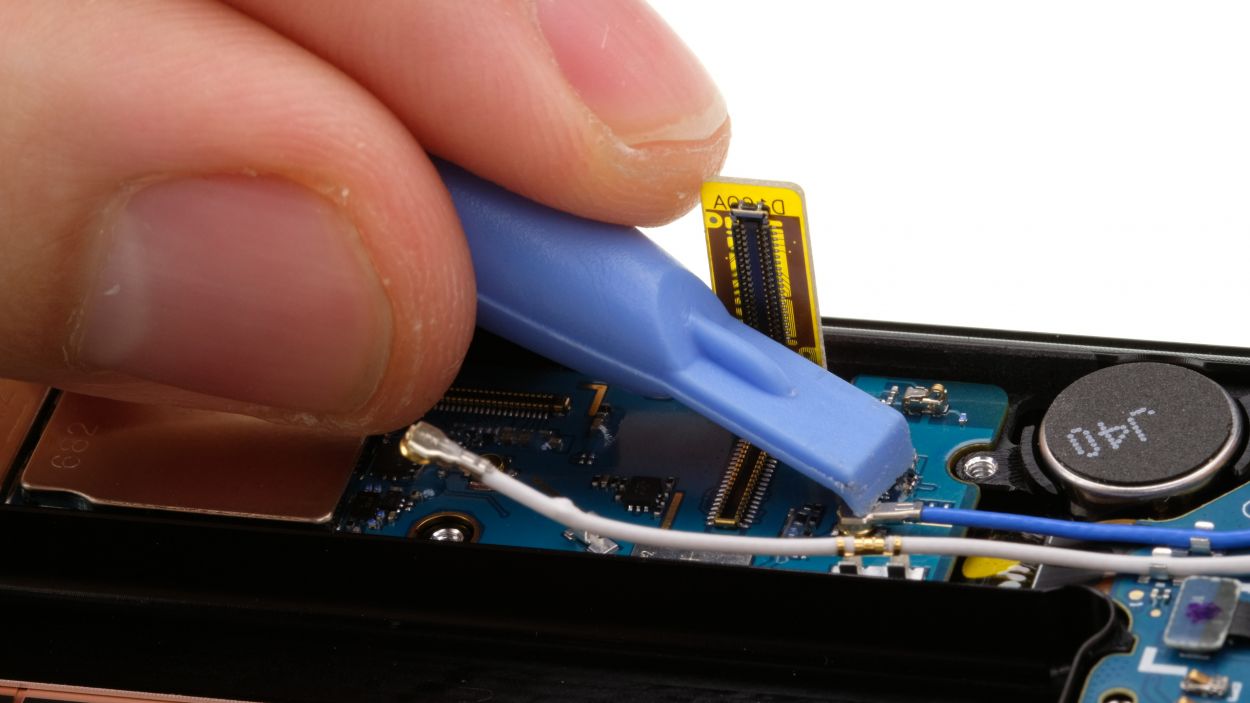
– Hey there! Before you pop that back cover on, make sure to connect the fingerprint sensor. It’s a little step that makes a big difference!
– Grab a plastic tool to help you reach that connector. You’ve got this!
Step 31
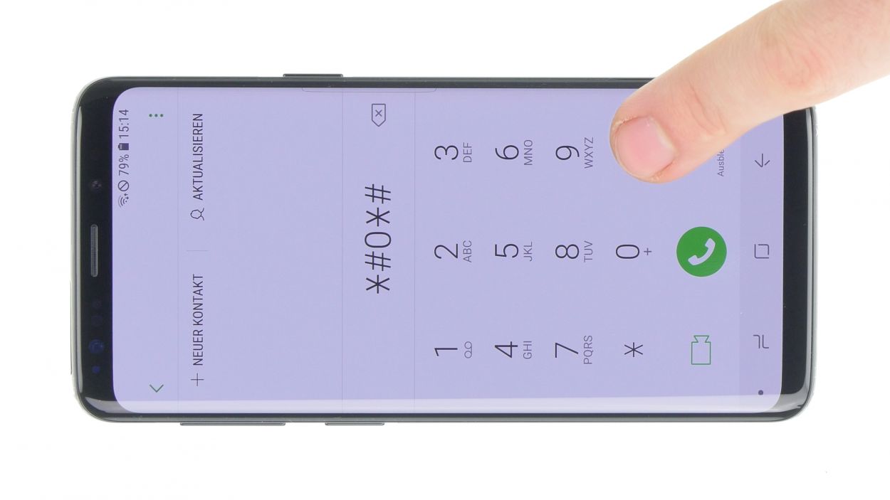
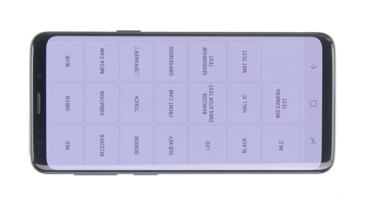

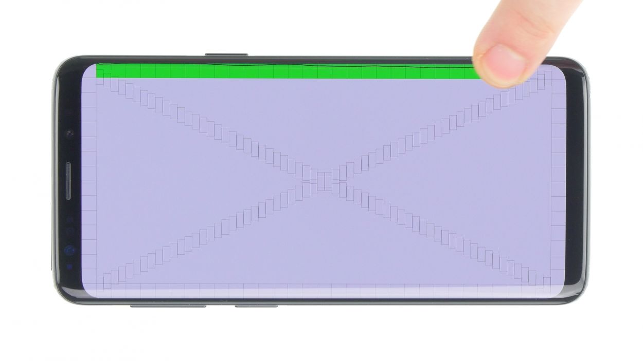
Check out the groovy pics of that Galaxy S9! The test menu is the same for all the cool Samsung Galaxy models.
– Fire up your Galaxy Note 8 and give it a whirl with the built-in test mode.
– To dive into the test mode, just dial *#0*#.
– Keep an eye on your screen and follow the prompts that pop up.
Step 32


You
can also heat your device with hot air and then clamp it or weight it
down with a couple books so the glue will stick better.
– Gently place the back cover back where it belongs.
– Give the back cover a little love by pressing down all around so the glue can do its magic.