DIY Guide to Remove the PCB on Moto X Play – Step-by-Step
Duration: 60 min.
Steps: 16 Steps
In this guide, we’re here to help you tackle the task of removing your Moto X Play’s PCB all by yourself! If your device has taken a dip and needs some TLC after water damage, getting that PCB out is the first step to making it shine again. Let’s get started!
Step 1
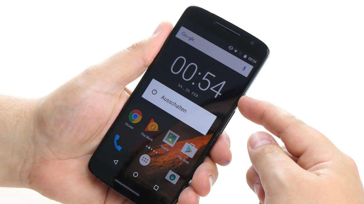
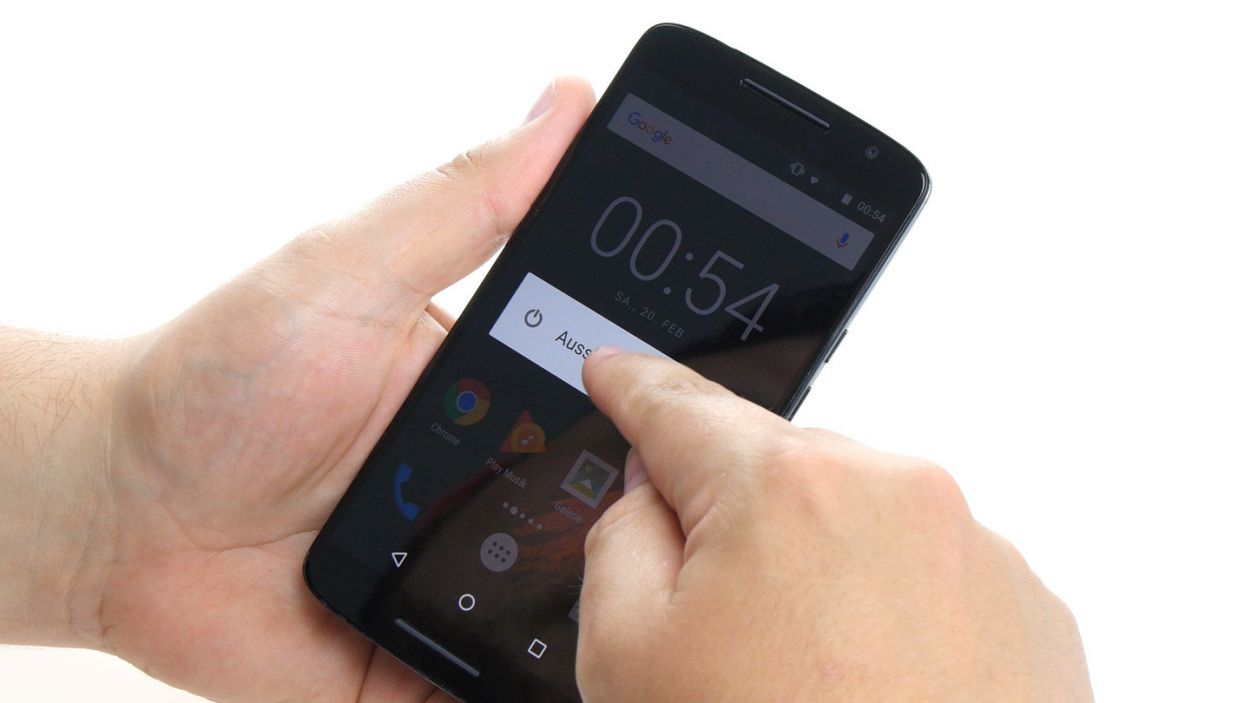
– First things first, let’s give your device a little nap! Press and hold that power button until you see the ‘Power off’ option pop up on your screen.
– Now, just tap that option with your finger to confirm you want to shut down your Moto X Play. Sit back and relax while you wait for the screen to fade to black.
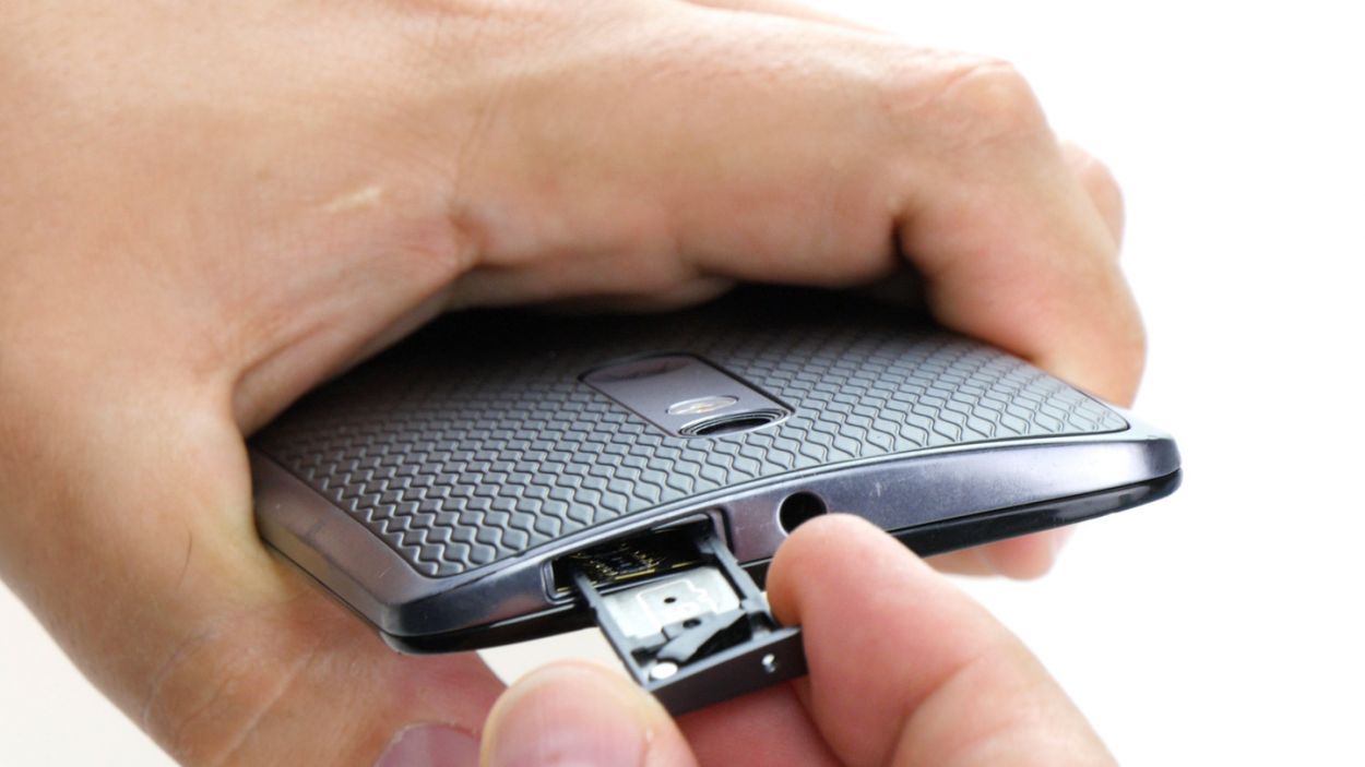
Step 2


– Let’s get that SIM tray out! Grab a SIM tool (or a straightened paperclip – you’re resourceful!) and gently nudge it into the tiny hole.
– Once you see the tray peeking out, give it a gentle tug and pull out those cards. Easy peasy!
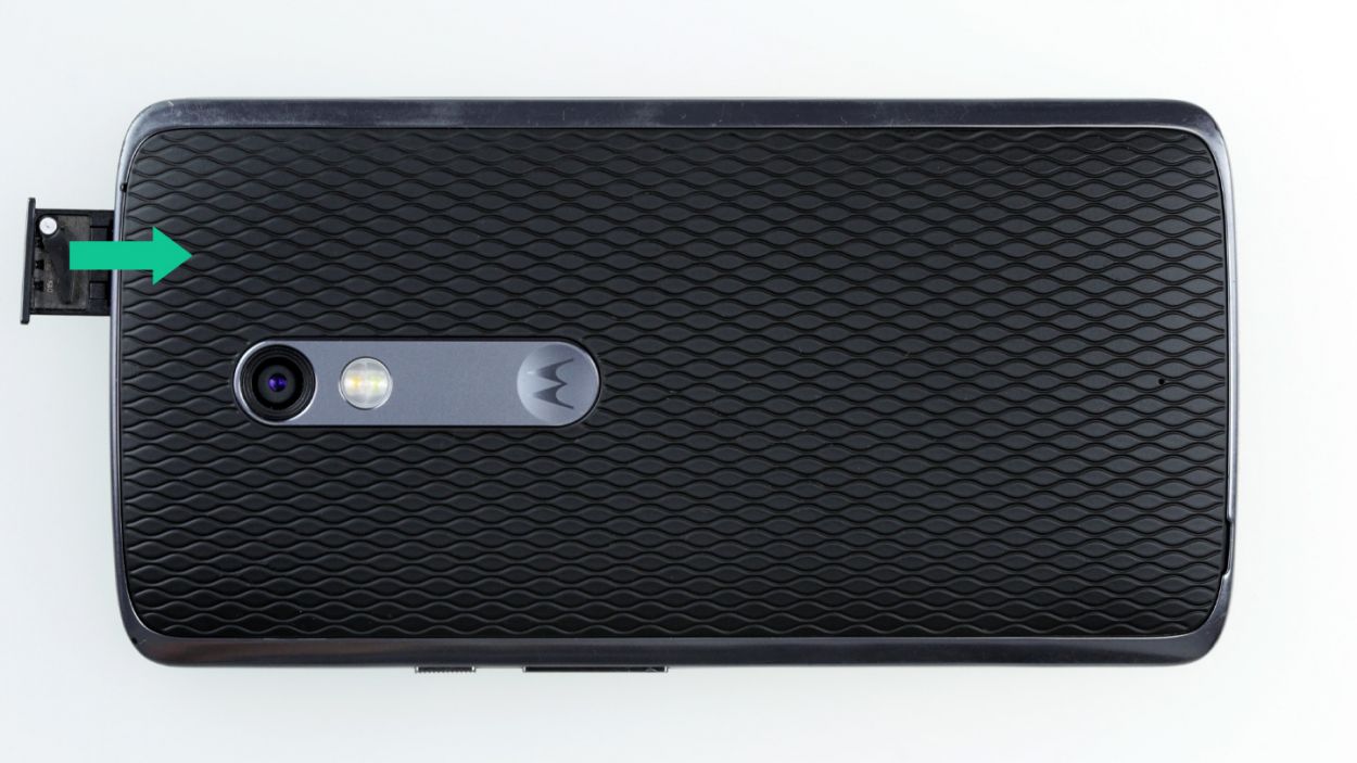
Step 3
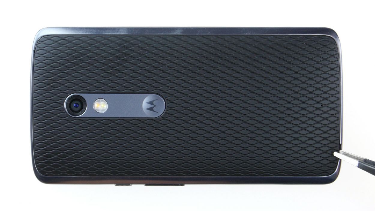
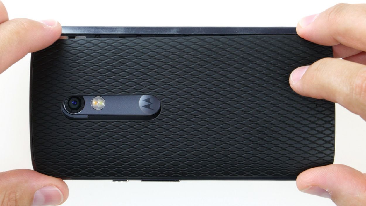
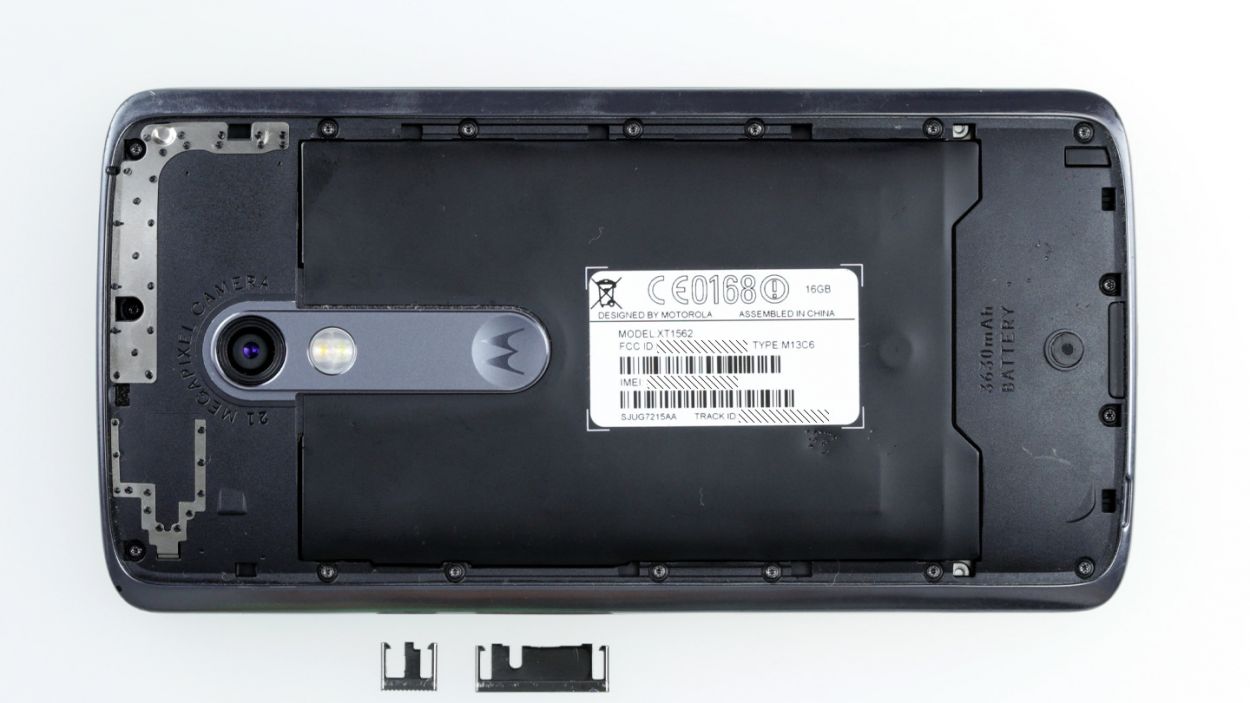
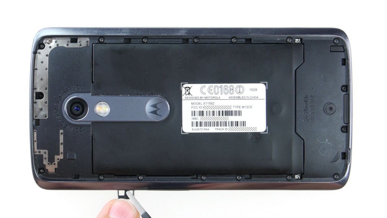
– In the lower left corner of the back cover, you’ll find a handy little slot. Just slide your fingernail or a tool in there and gently pry the back cover away from your device.
– The cover is secured to the chassis at a few points. Take your time to unhook all those connections and carefully lift the back cover off your device.
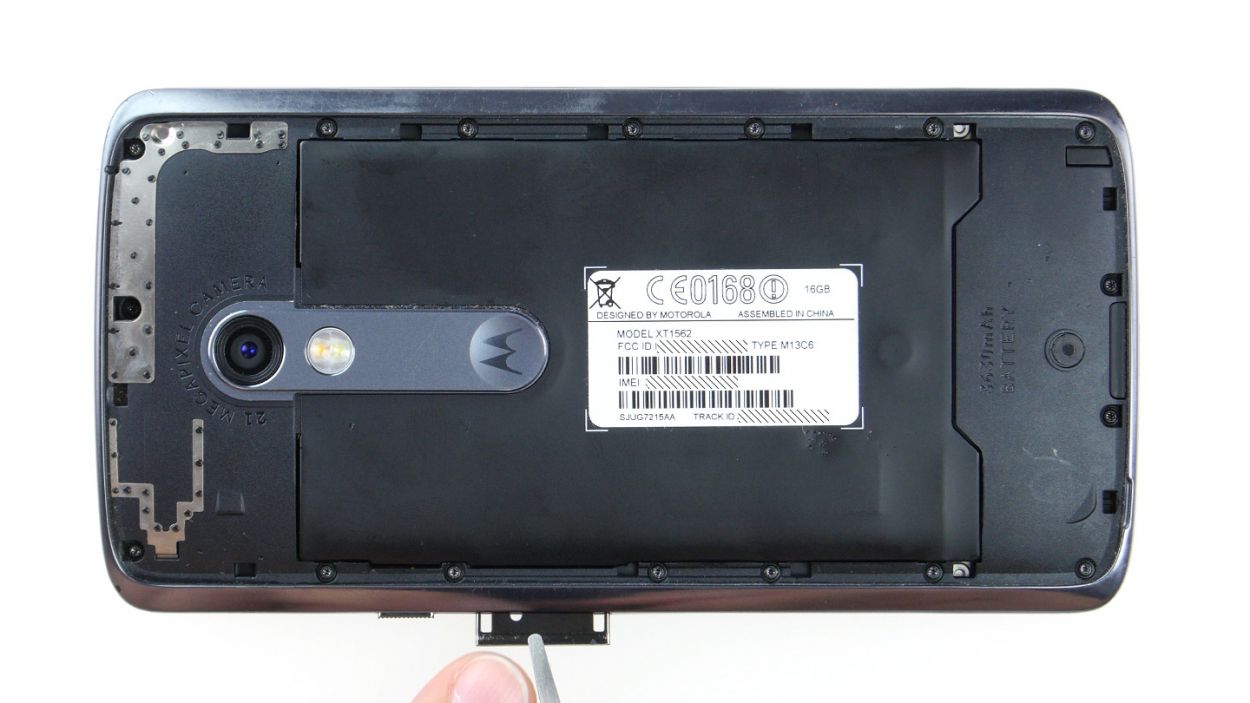
Step 4
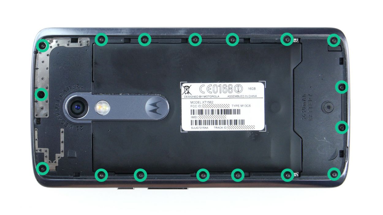
– Let’s get this party started! First, unscrew those 17 tiny 3.1 mm T3 Torx screws holding the midframe – they’re eager to come out and play.
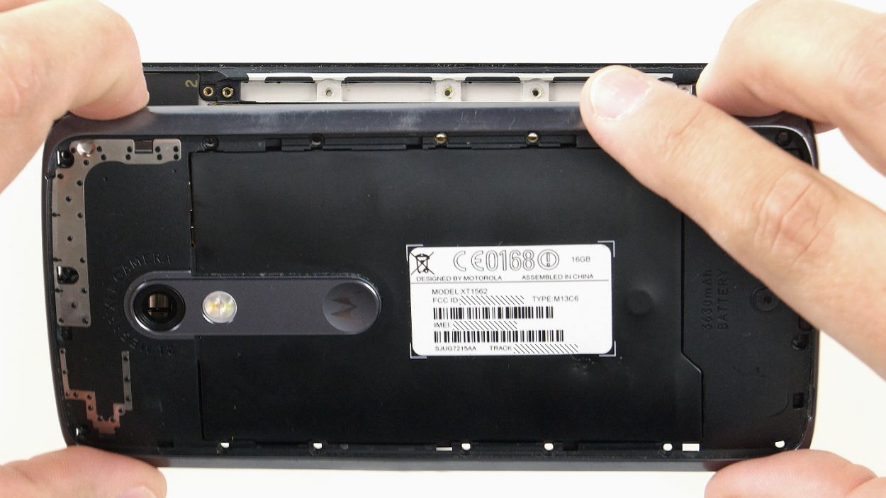
– Now, gently remove the midframe. Those power and volume buttons might do a little dance and decide to join the party early. If they don’t, that’s cool – you can always give them a gentle nudge later.
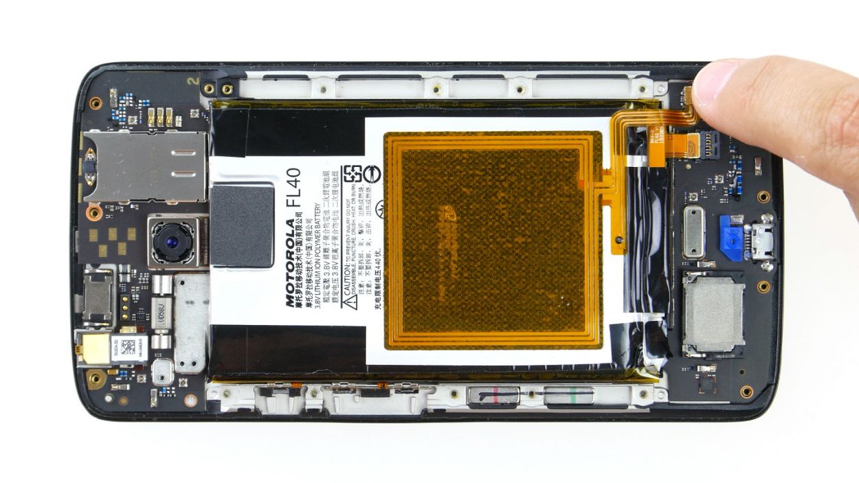
Step 5
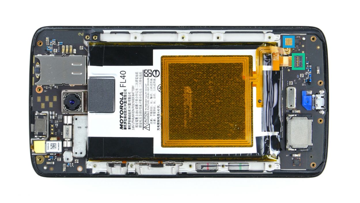
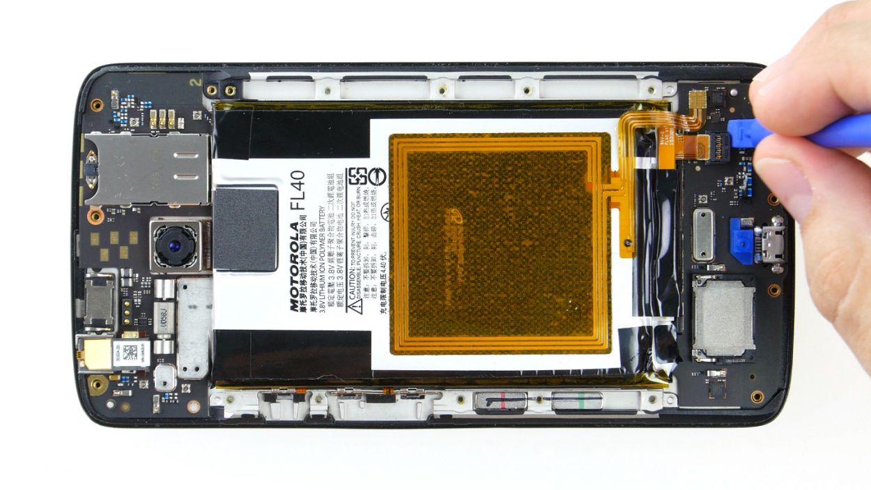
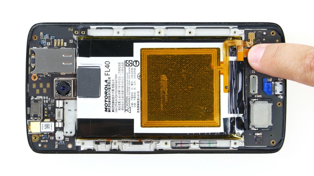
– Unplug the two connectors for the battery and the NFC antenna from the PCB. It’s like giving your device a little break!
– Gently use the spudger to disconnect the connectors. Slide the blade under the contact and carefully lift it out of the socket. You’re doing great!
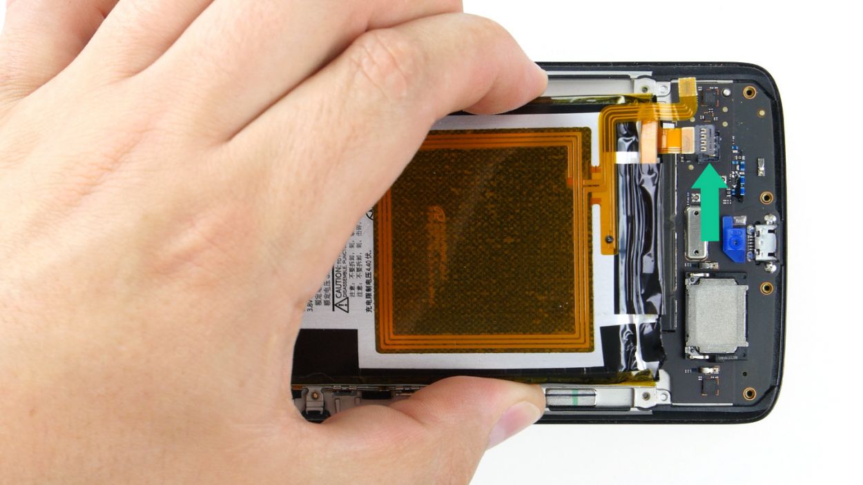
Step 6
Take it easy during this step! Grab a flat, blunt tool like the round end of a steel laboratory spatula to gently navigate around the battery and PCB. We want to keep everything safe and sound!
– Alright, let’s tackle that battery! It’s stuck on the PCB with some serious glue. The easiest way to get it off is to gently slide your tool between the battery and the metal strips on both long sides. Then, use your tool as a lever to pop it loose. Most of the glue should come off with it!
– Once you’ve loosened it up a bit, you can lift the battery slightly and carefully slide your tool underneath. Just be super cautious here—nobody wants to damage that PCB!
– Now, go ahead and remove the battery from its cozy home in the enclosure.
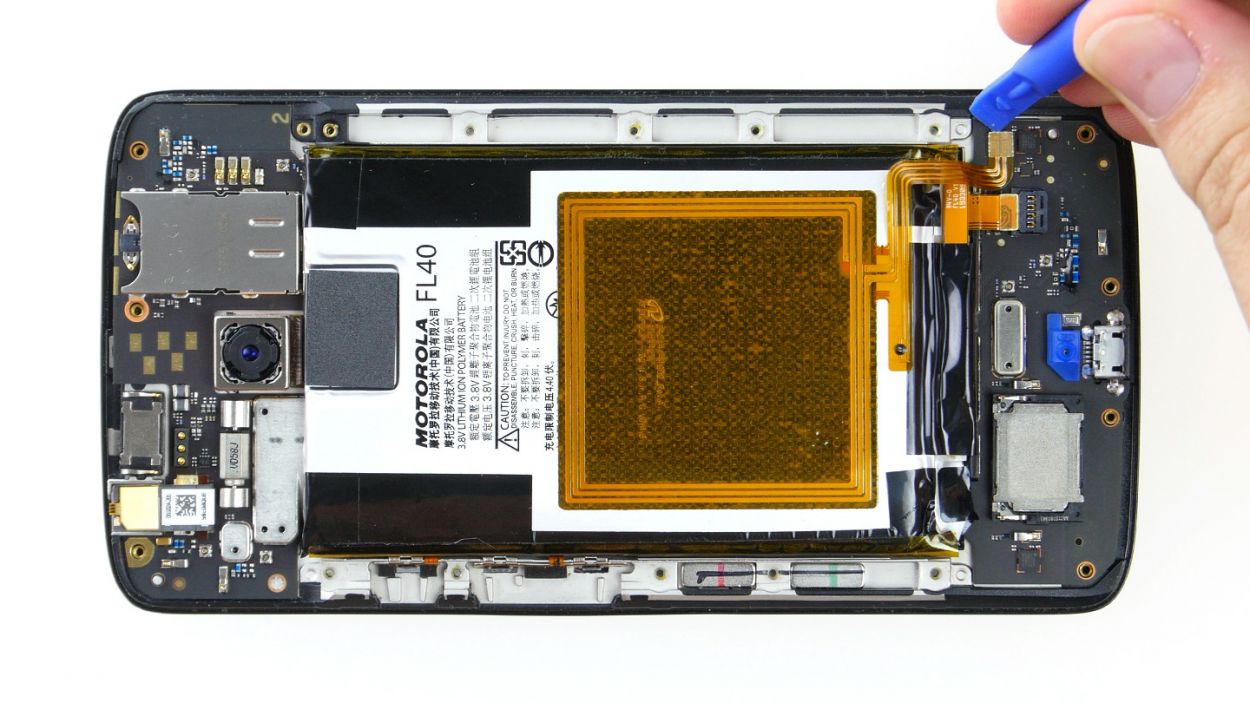
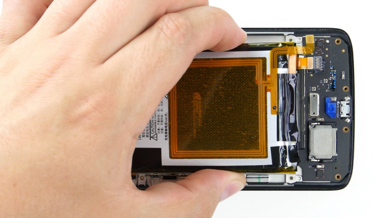
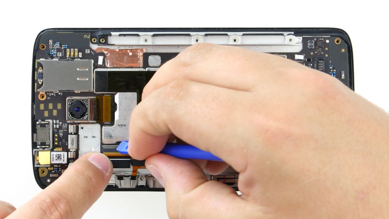
Step 7
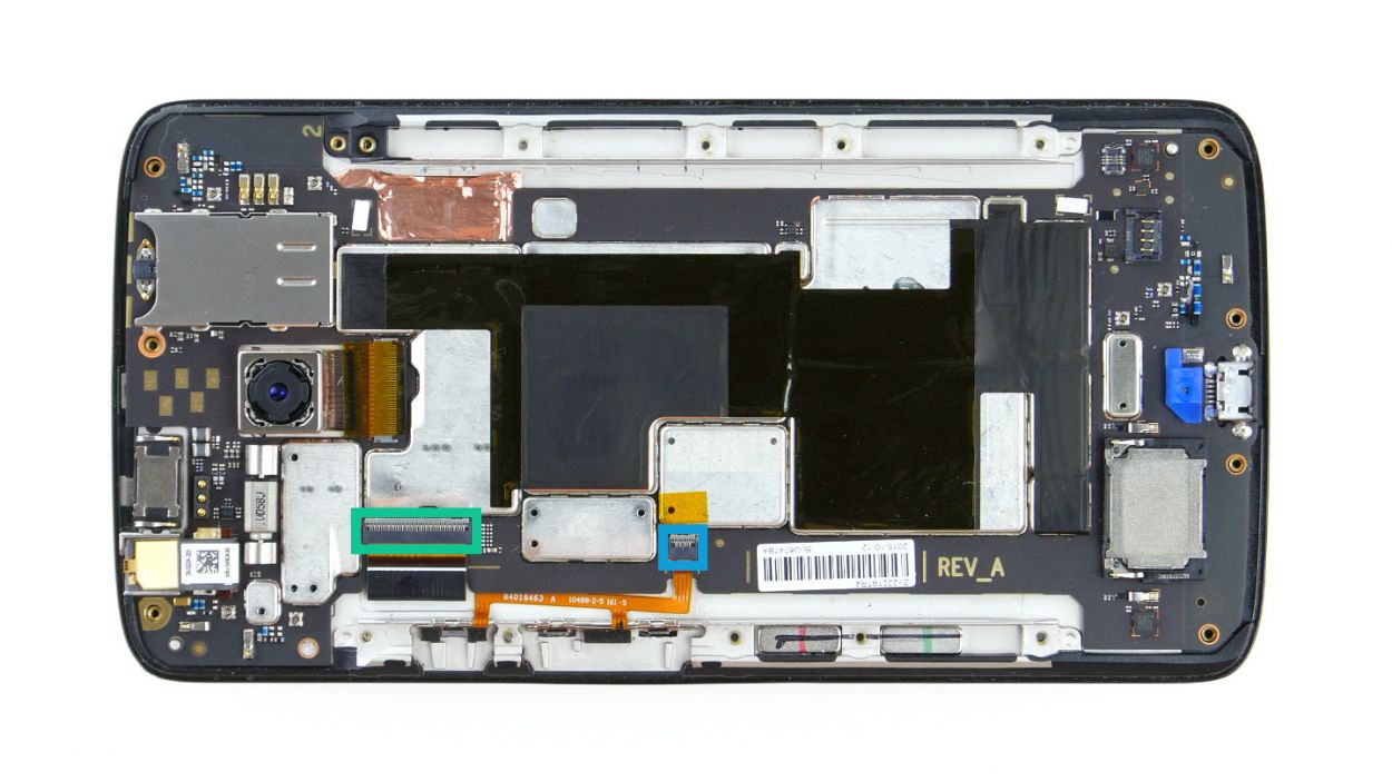
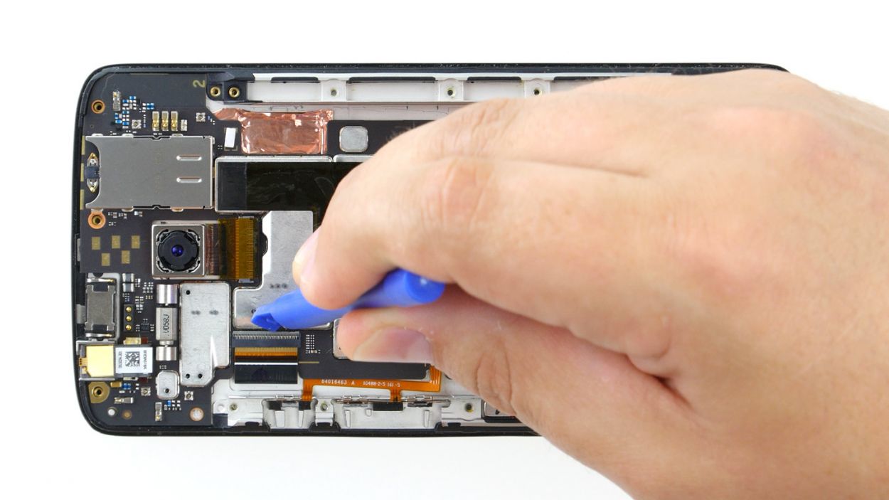
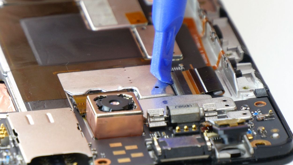

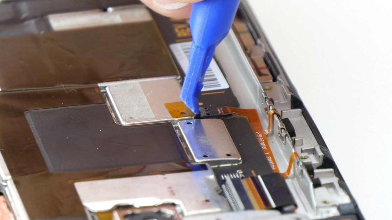
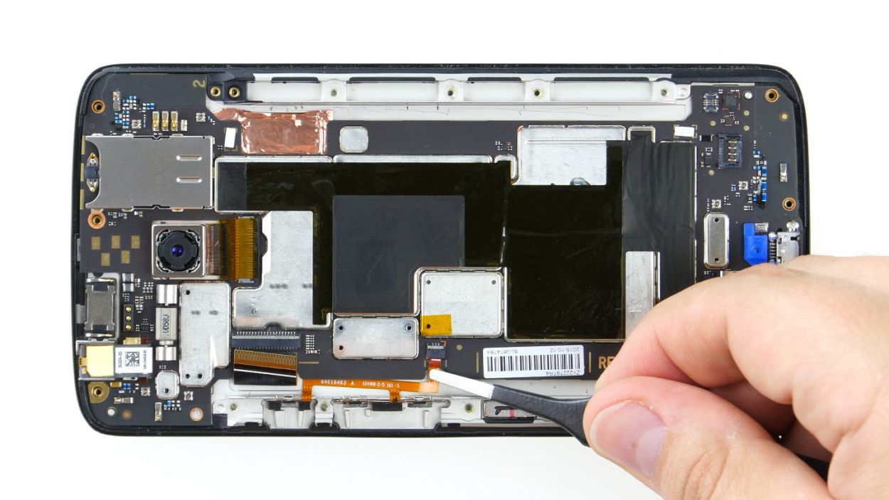
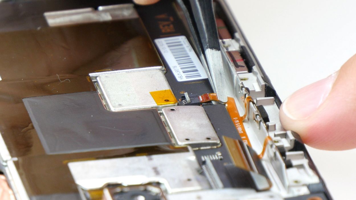
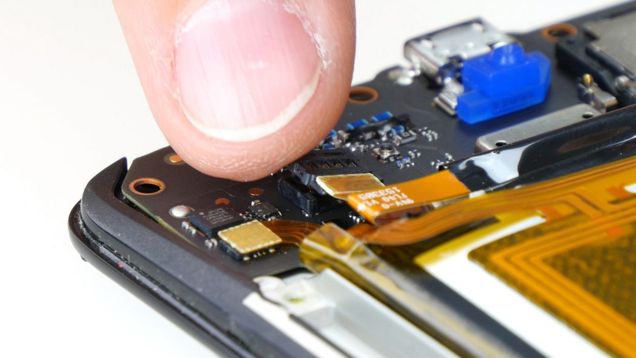
– First, gently detach the two plug contacts for your display and control buttons from the PCB. Take it easy, it’s just a little unplugging!
– Now, grab your trusty spudger and carefully separate those two brackets on the sockets. Just slide the blade under each bracket and give it a gentle lift – no need to brawl with it, we’re all friends here.
– Once that’s done, gently pull the two cables out of their sockets. Remember to use just a tiny bit of force – we definitely want to avoid any bending or tearing of those delicate cables!
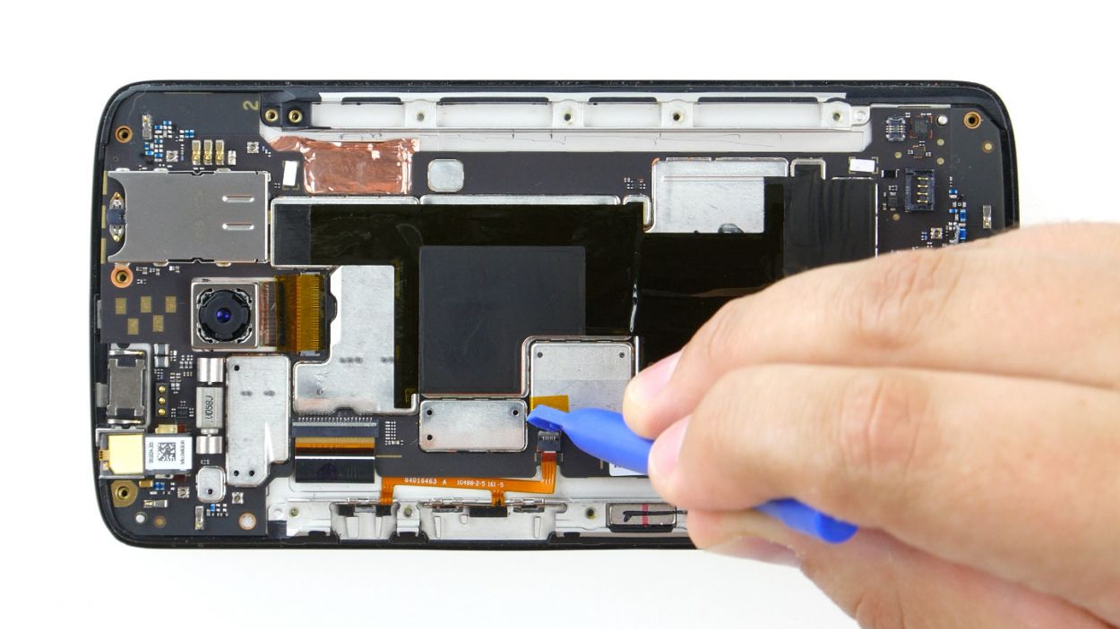
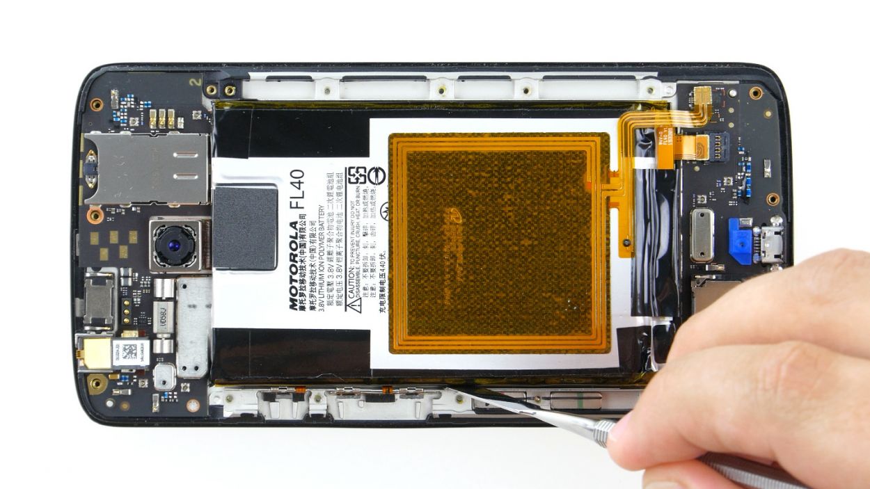
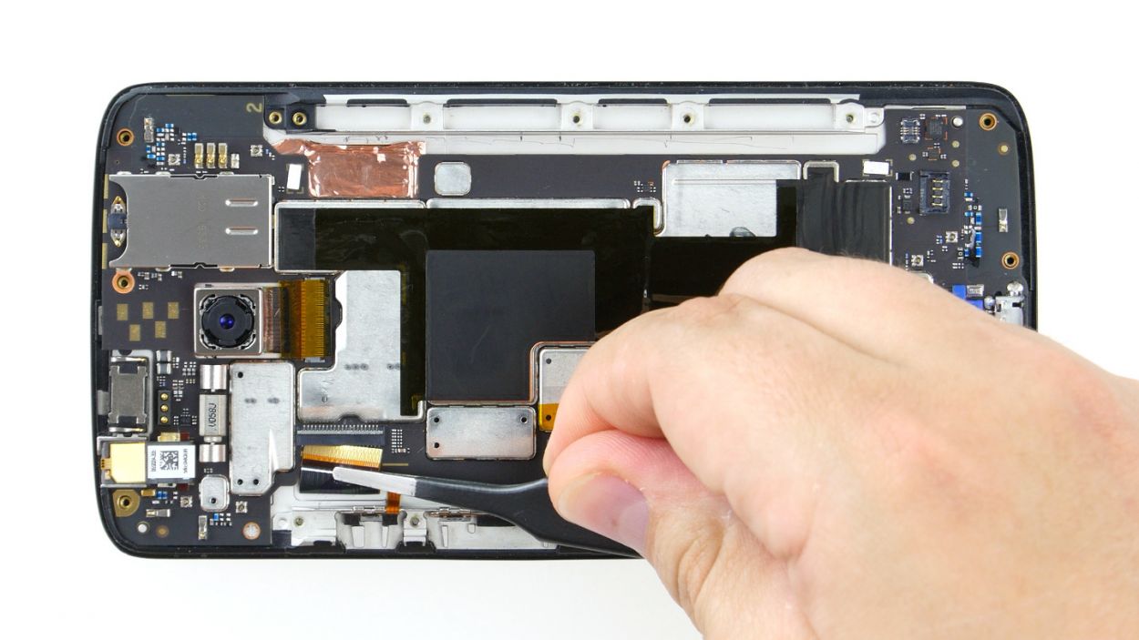
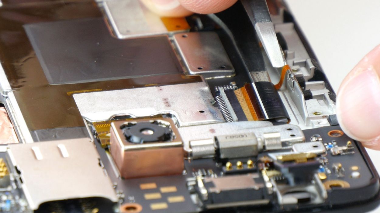
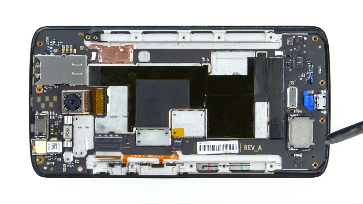
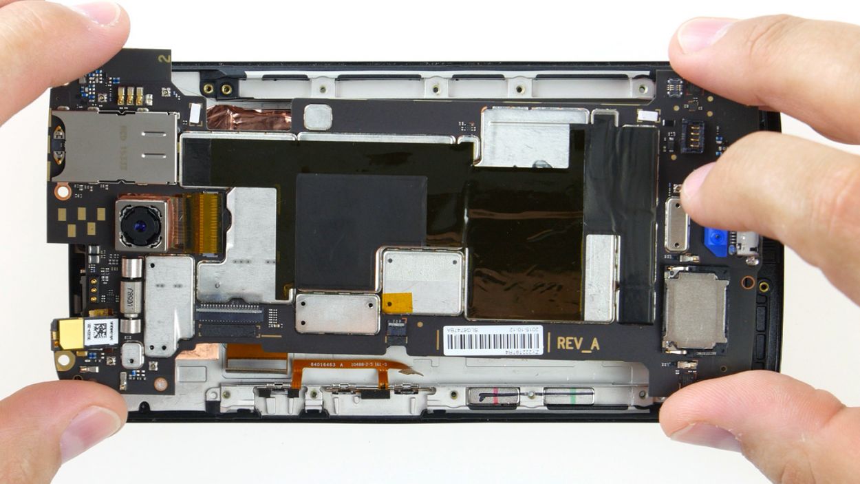
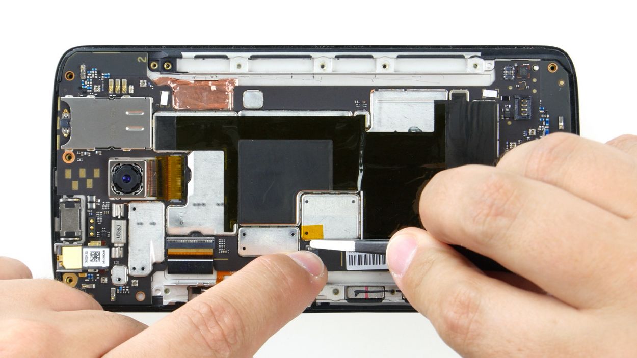
Step 8
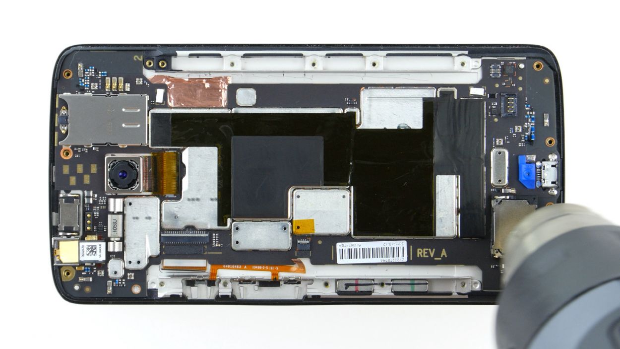
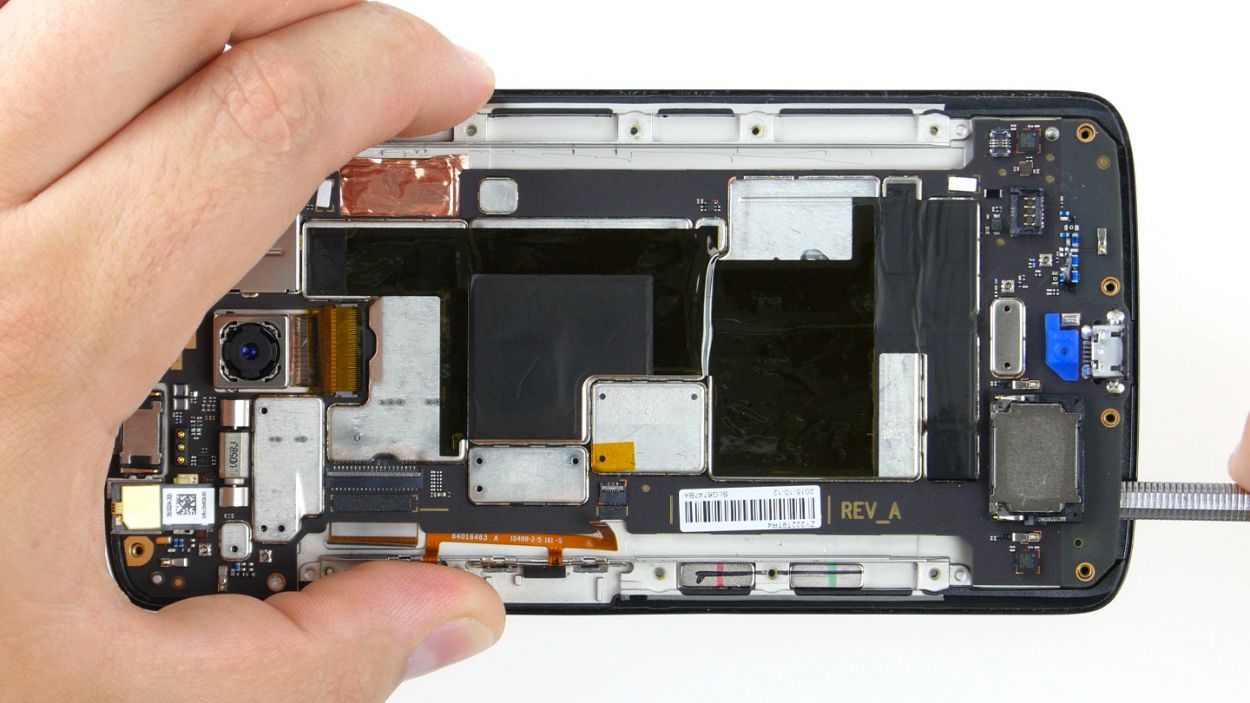
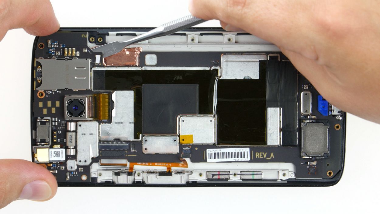
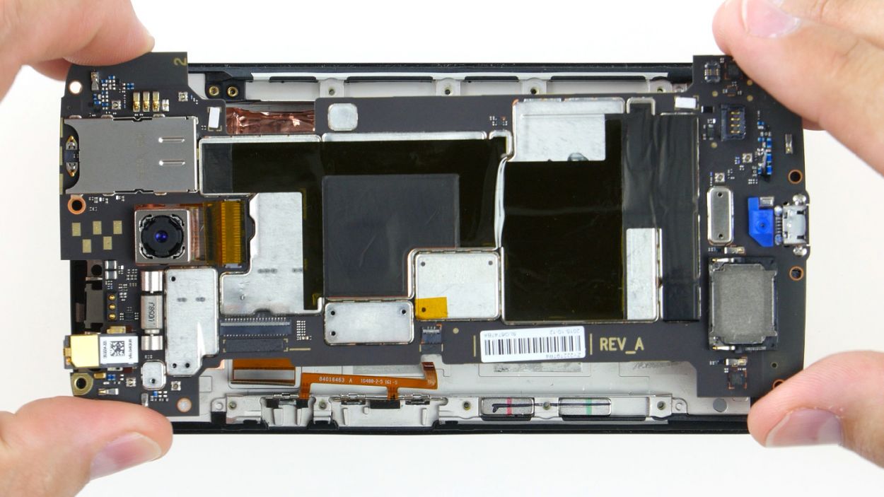
Take it easy during this step, folks! Grab a flat, blunt tool like the rounded end of a steel laboratory spatula to keep your PCB safe and sound. We know you got this!
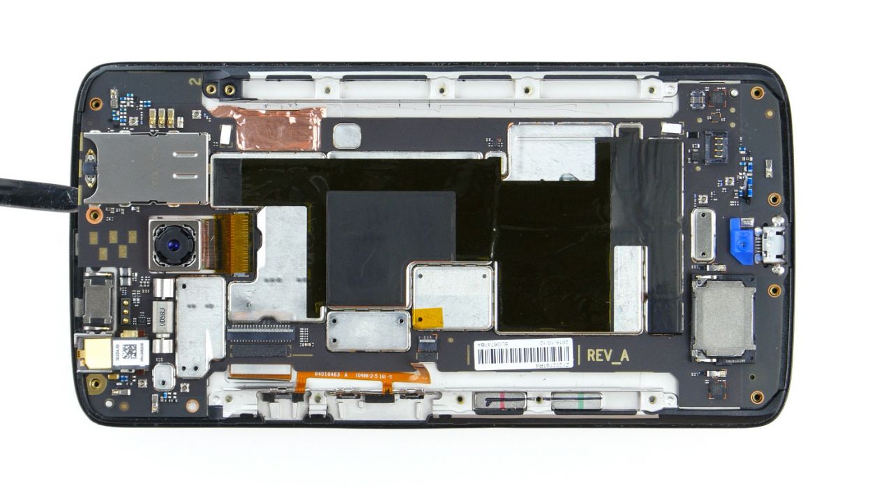
– Let’s get this party started! Time to warm up your device with some hot air to loosen that stubborn glue.
– That PCB is stuck like glue to the case – gently persuade it to come out. Take your time; we don’t want any accidental injuries to the components or PCB!
– Use your tool to wiggle and jiggle around all the edges to free up that PCB. It’s like a puzzle, but better!
– Once you get a tiny bit of lift, sneak your tool in further to break the glue’s grip.
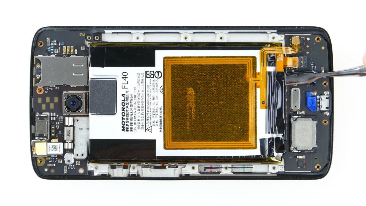
– Woohoo! You’re almost there. Time to carefully remove that motherboard. If you need a hand, you can always schedule a repair.
Step 9
– Put the PCB back in the enclosure and press it against the enclosure so the glue will stick again. Make sure no cables get stuck below the PCB.
Step 10


– First up, let’s connect those two plug contacts for the display and the control buttons to the PCB. Easy peasy!
– Now, gently slide each cable back into its respective socket. Make sure to push it all the way in for a solid electrical connection. Remember, no bending or tearing those cables!
– Finally, give those brackets a little press down to lock the cables snugly in their sockets. You’re doing great!
Step 12

– Reattach the battery contact along with the NFC antenna connector to the PCB like a champ! The NFC antenna is your friend here.
– With your finger, gently press both connectors into their designated spots. Listen for that satisfying click as they secure themselves in place!
Step 13


– Alright, it’s time to put the midframe back on! Make sure it’s lined up properly so all the openings match up with the threaded holes on the device.
– Now, grab those seventeen screws and get ready to attach the midframe to the device. You’ll need a 3.1 mm T3 Torx screwdriver for this part. Don’t worry if it takes a little elbow grease – you got this! If you need help, you can always schedule a repair
Step 14
– Don’t forget to pop those two buttons back in for the power and volume controls! Just align them like you see in the first picture and slide them into their cozy little homes. You’ll hear a satisfying click when they snap into the enclosure, letting you know they’re all set!
Step 15

– Carefully place the back cover back where it belongs on your device.
– Give it a gentle press all around until you hear those satisfying clicks from the hooks locking into place.
Step 16
– Insert the SIM tray back into your device. Make sure it’s aligned properly.