DIY Guide to Replace Moto G10 Screen Step-by-Step
Duration: 120 min.
Steps: 53 Steps
Hey there! Just a heads up: once you crack open your device, the IP certification that keeps dust and water at bay will be on a countdown. So, keep that in mind while you dive into the repair!
If you’re looking to swap out that screen, you’ve come to the right place! In this easy-to-follow photo guide, we’ll walk you through each step to make the process a breeze.
Step 1
Before diving into the repair of your Motorola moto g10, why not give our handy checklist a whirl? It’s a great way to test out the basic functions and see how things are running. Plus, once you’re done, you’ll know if your repair was a success. Let’s get this show on the road!
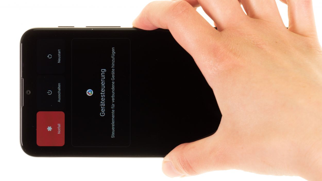
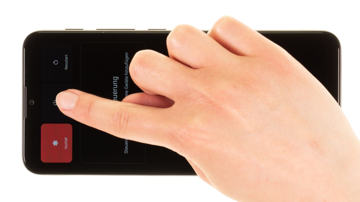
– Give that power button a good press and hold until you see the Power Off menu pop up on your screen. It’s like magic!
– Now, just tap on Power off in that menu. Your smartphone will gracefully power down in just a few seconds. Easy peasy!
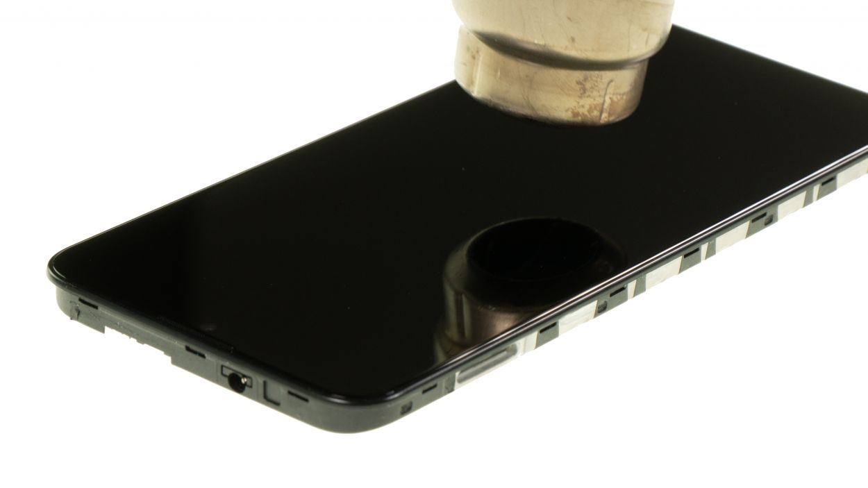
Step 3
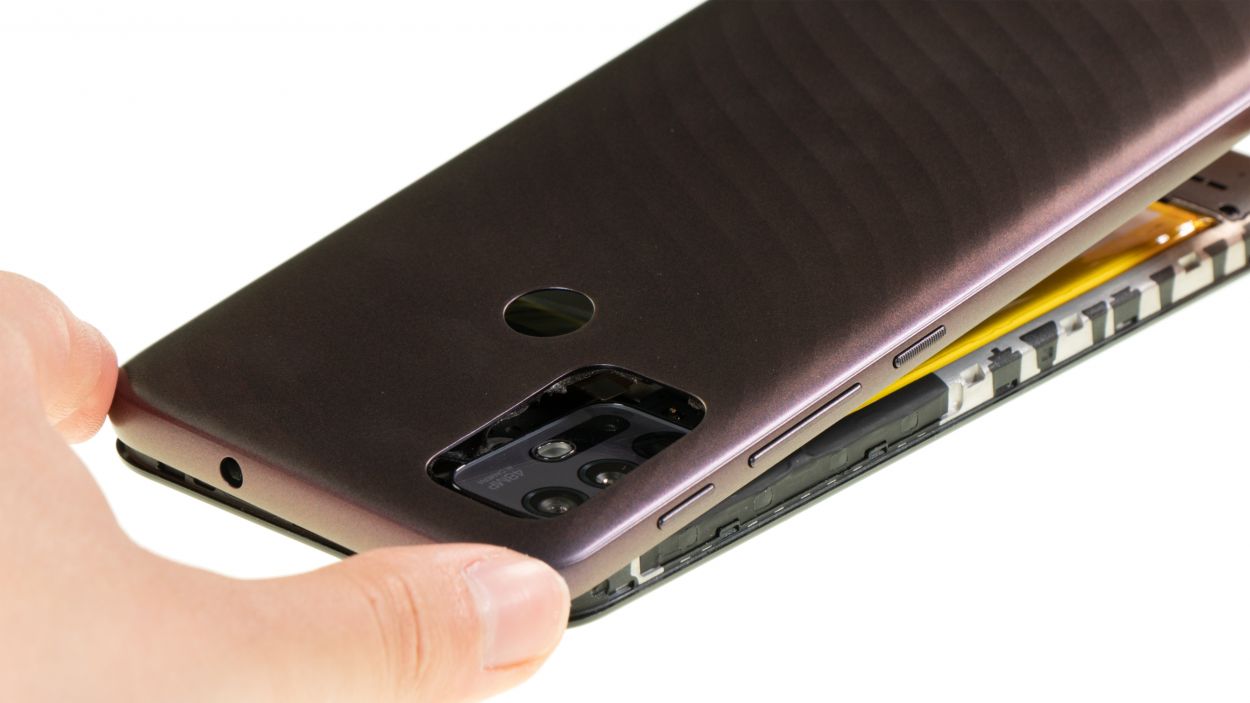
– Gently slide your tool under the edge of the back cover, like you’re tucking in a cozy blanket.
– Now, glide that tool around the back cover, piece by piece. You’ll hear those hooks with the screen unit loosening up, and trust me, it’ll be music to your ears!
Hey there, just a heads up! The frame might be a little wobbly, especially around where the SIM tray used to hang out. So, take it easy and tread carefully at this point!
The plastic back cover is snugly attached to the screen unit and has a bit of glue holding it in place. You can easily loosen it up with a flat plastic tool, like a pick or the handy iPlastix. Get ready to tackle this with confidence!
Tools Used
- Flat Picks
- battery? Then the iPlastix with its large blade will help you. The practical assistant is made of flexible, especially sturdy plastic and lies comfortably in the hand. Thanks to its design, you can even get into smaller gaps, for example to lift the screen or to prevent it from sticking together again.” rel=”noopener”>iPlastix Opening Tool
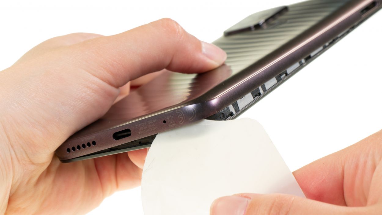
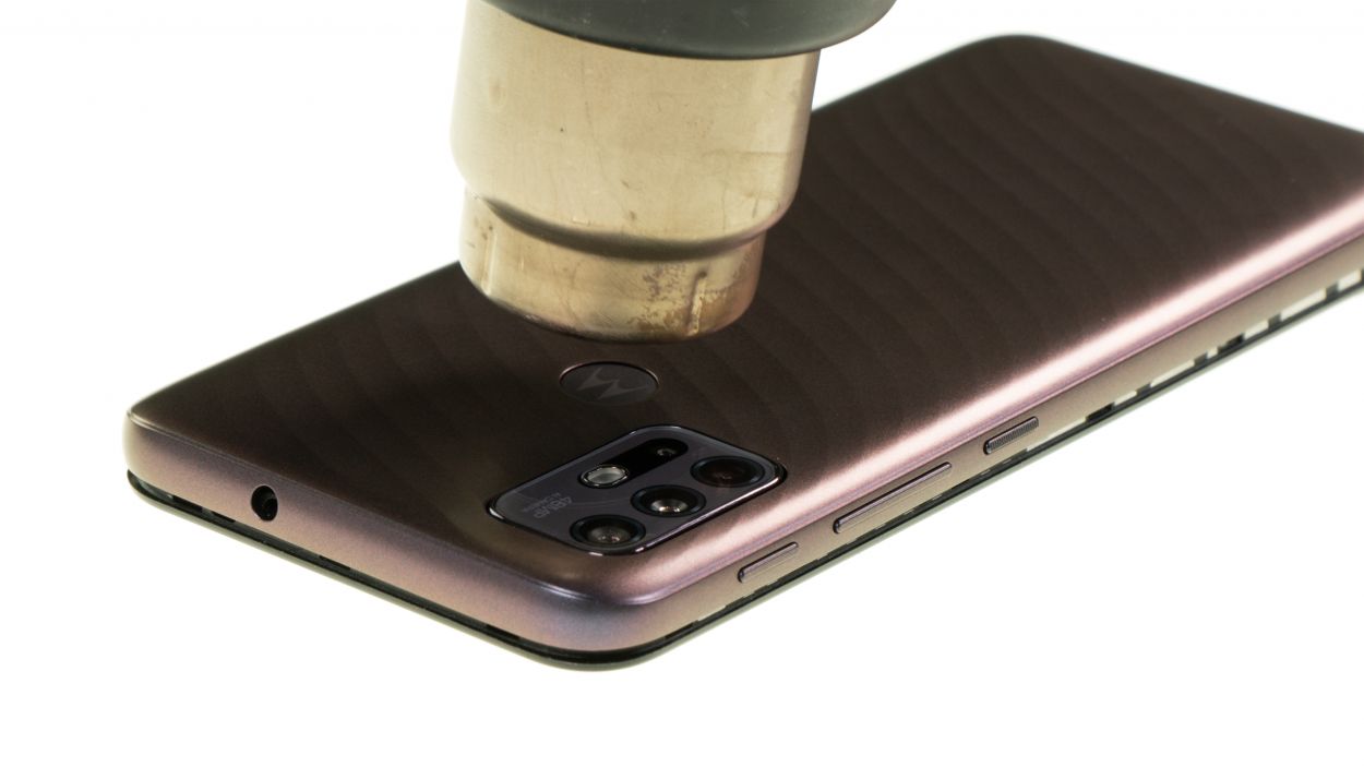
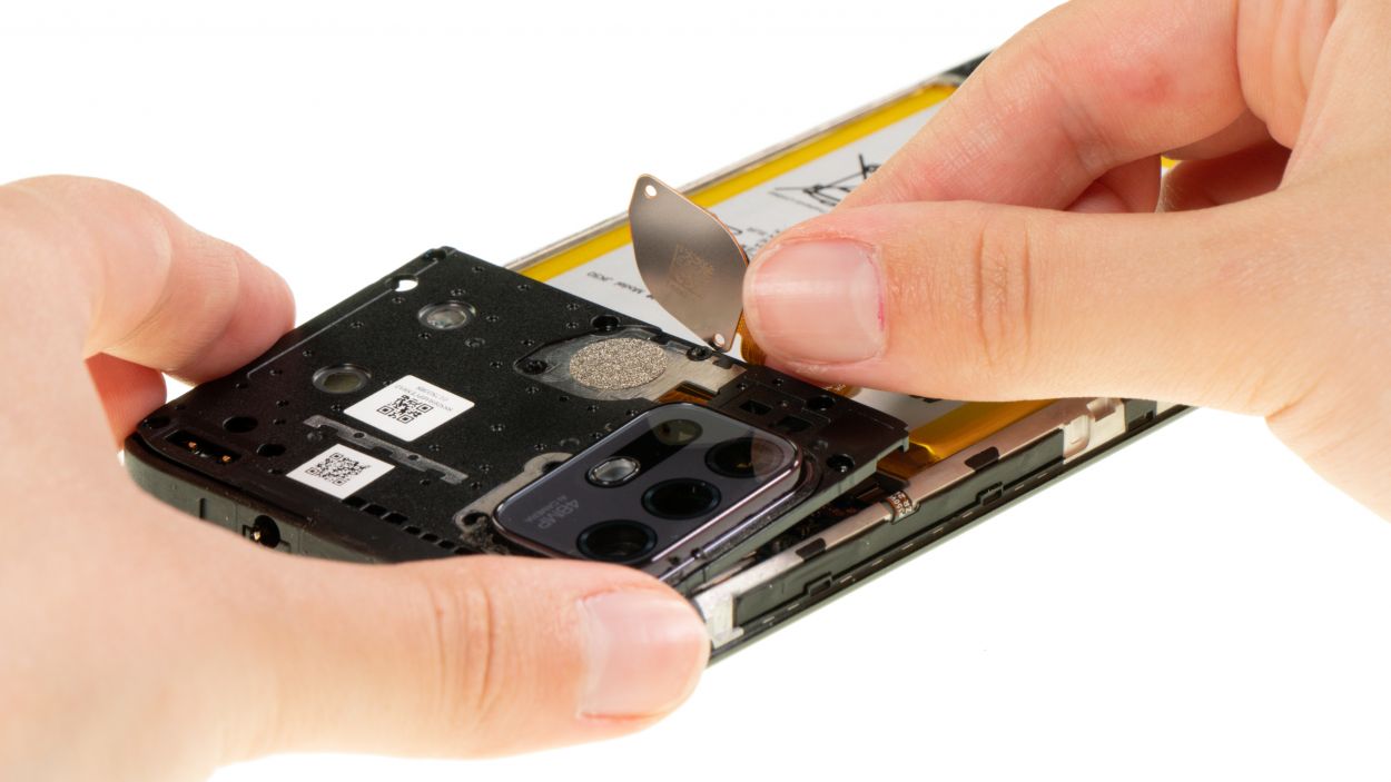
Step 4
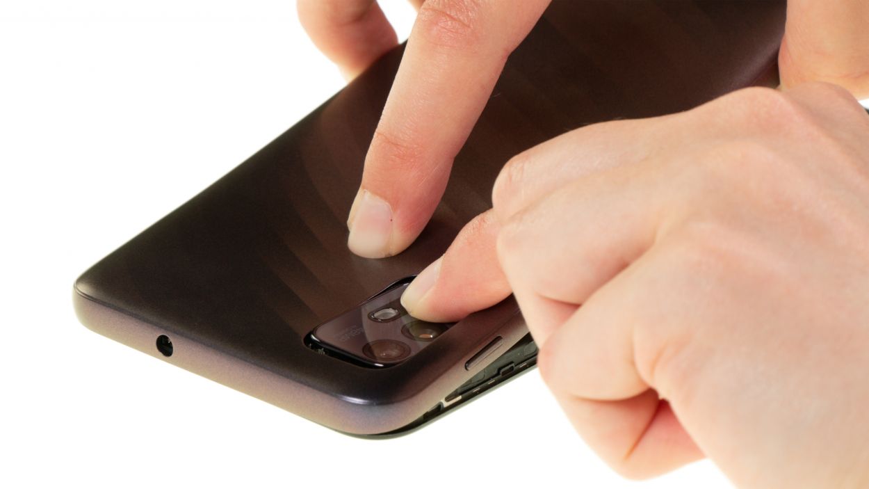
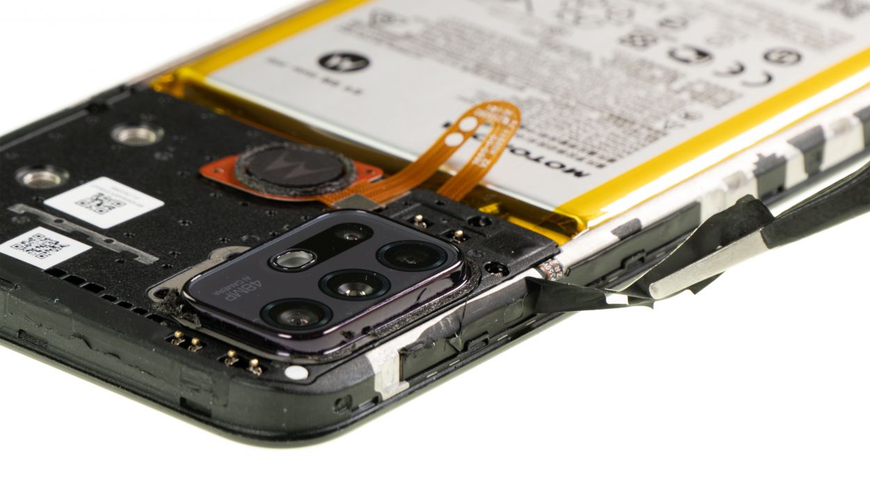
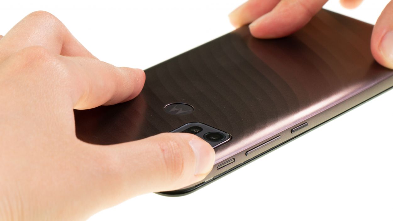
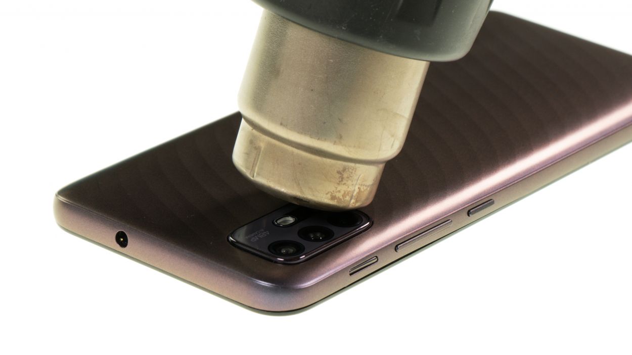
When you’re popping off that back cover, give a gentle press on the camera module and fingerprint scanner to keep them safe and sound from any unexpected detachment!
The back cover is held in place with glue around the camera module and fingerprint scanner. Just a little adhesive love to keep everything snug and secure!
– Give that adhesive a little love by warming it up with a hot air tool for a moment. A heat gun works wonders, but if you’ve got a trusty hair dryer, that’ll do the trick too!
– Gently peel off the back cover with care.
Tools Used
- heat gun to heat parts that are glued on so they’re easier to remove.
In most cases, you can also use a hairdryer.” rel=”noopener”>Heat gun
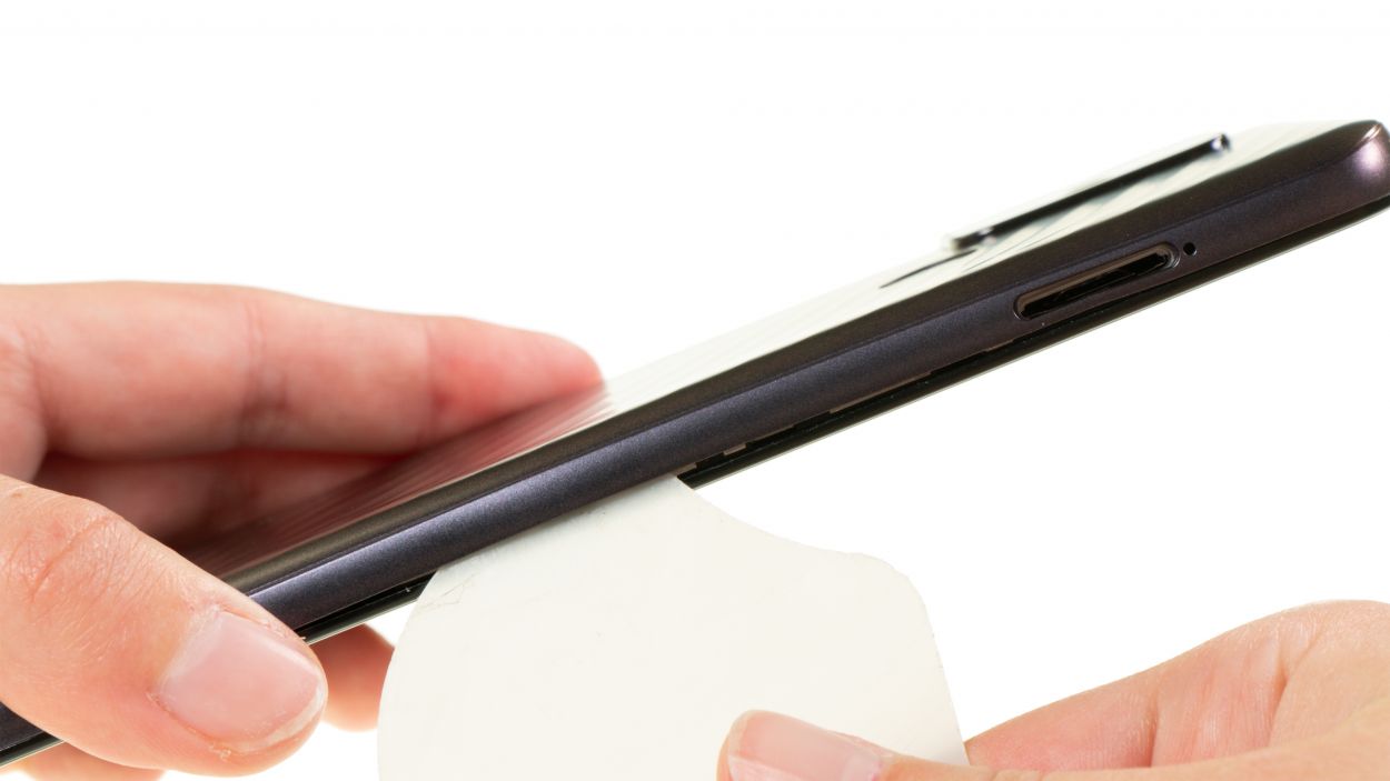
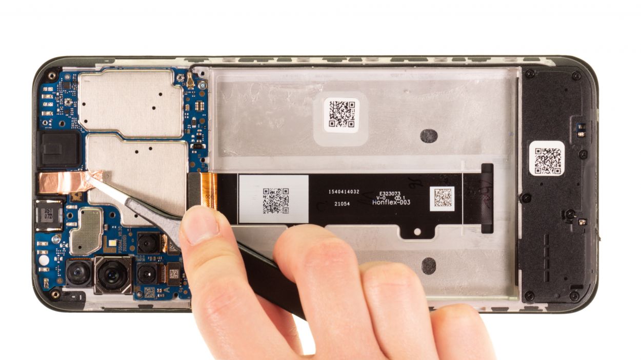
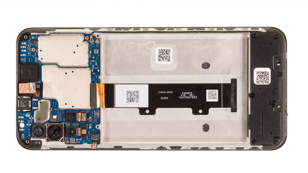
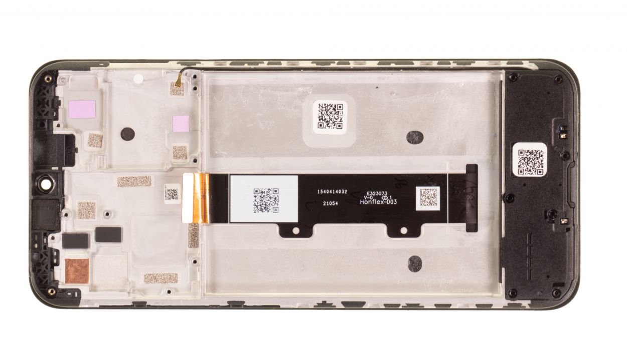
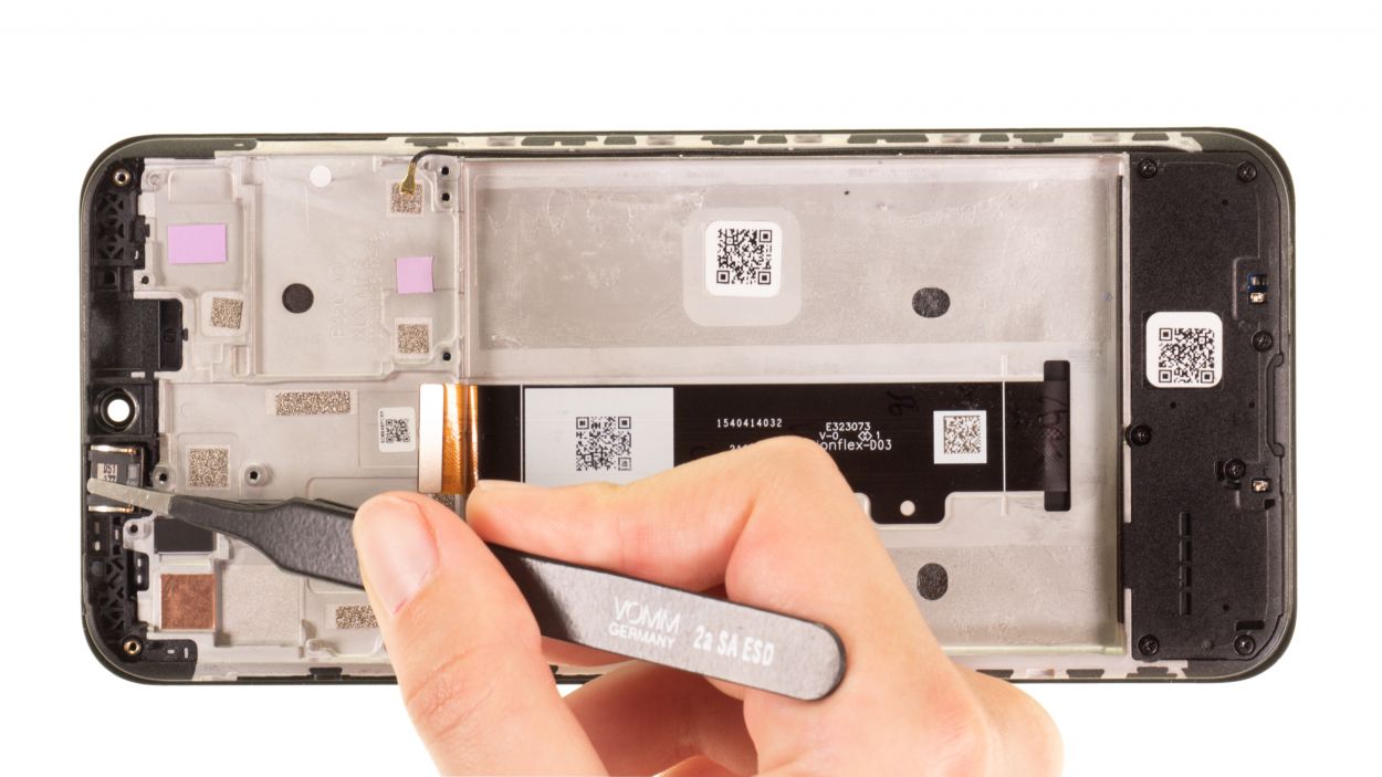
Step 5
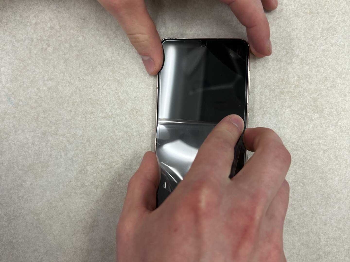
Hey there! Before we dive in, let’s take a moment to peel off those pesky strips of protective film around the edge of the screen unit. They’re blocking the screws, and we definitely need those screws to be free and clear for our repair adventure!
– Gently remove the strips using tweezers, taking care not to rush it.
– If you’re not planning to use them again after the repair, feel free to toss them out!
Tools Used
Step 6
2 × 3.3 mm Phillips
7 × 3.9 mm Phillips
Keep your screws organized and in sight during your repair adventure to prevent any sneaky disappearances! An old sewing box works wonders for this. Plus, with our top-notch magnetic pad, you can rest easy knowing everything stays put. Happy repairing!
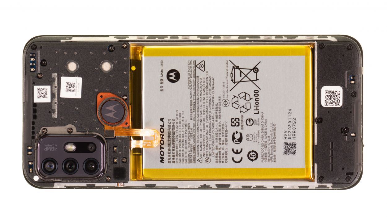
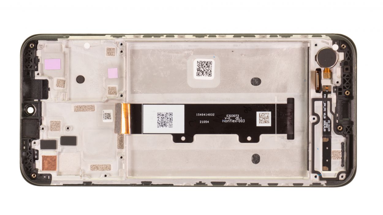
– Gently unscrew the nine Phillips screws holding that plastic cover snugly above the motherboard. You’ve got this!
– Place those little screws on the magnetic pad in a way that makes it super easy to spot the two different lengths later on. Organization is key!
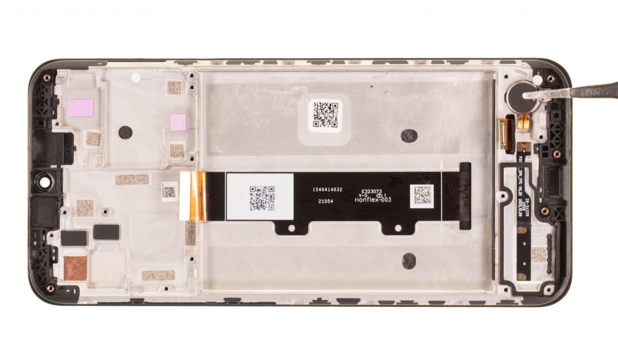
Step 7
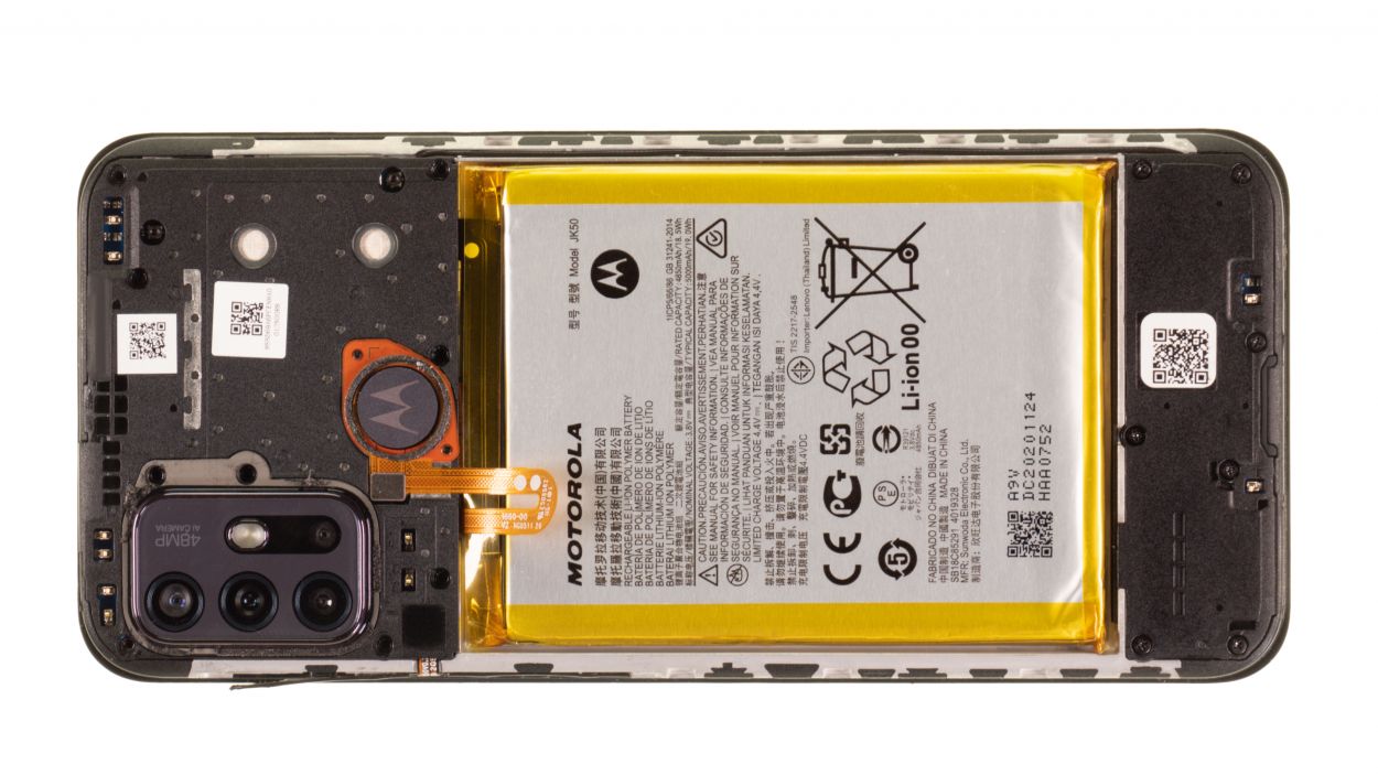
Hey there! Just a quick heads-up: the fingerprint sensor is hanging out on the plastic cover. To keep it safe and sound, make sure to gently set it aside while you’re removing that cover. You got this!
– Gently pry the plastic cover upwards, releasing the little lugs that keep it snugly attached to the screen unit. A trusty plastic spudger works wonders for this task.
– Set the fingerprint sensor aside and carefully lift out the loosened plastic cover from the device.
Tools Used
Step 8

Hey, safety first! Make sure to disconnect that battery connector ASAP to avoid any potential short circuits. If you need help, you can always schedule a repair
– Gently wiggle the battery connector free from the motherboard using a plastic spudger. You’ve got this!
Tools Used
Step 9
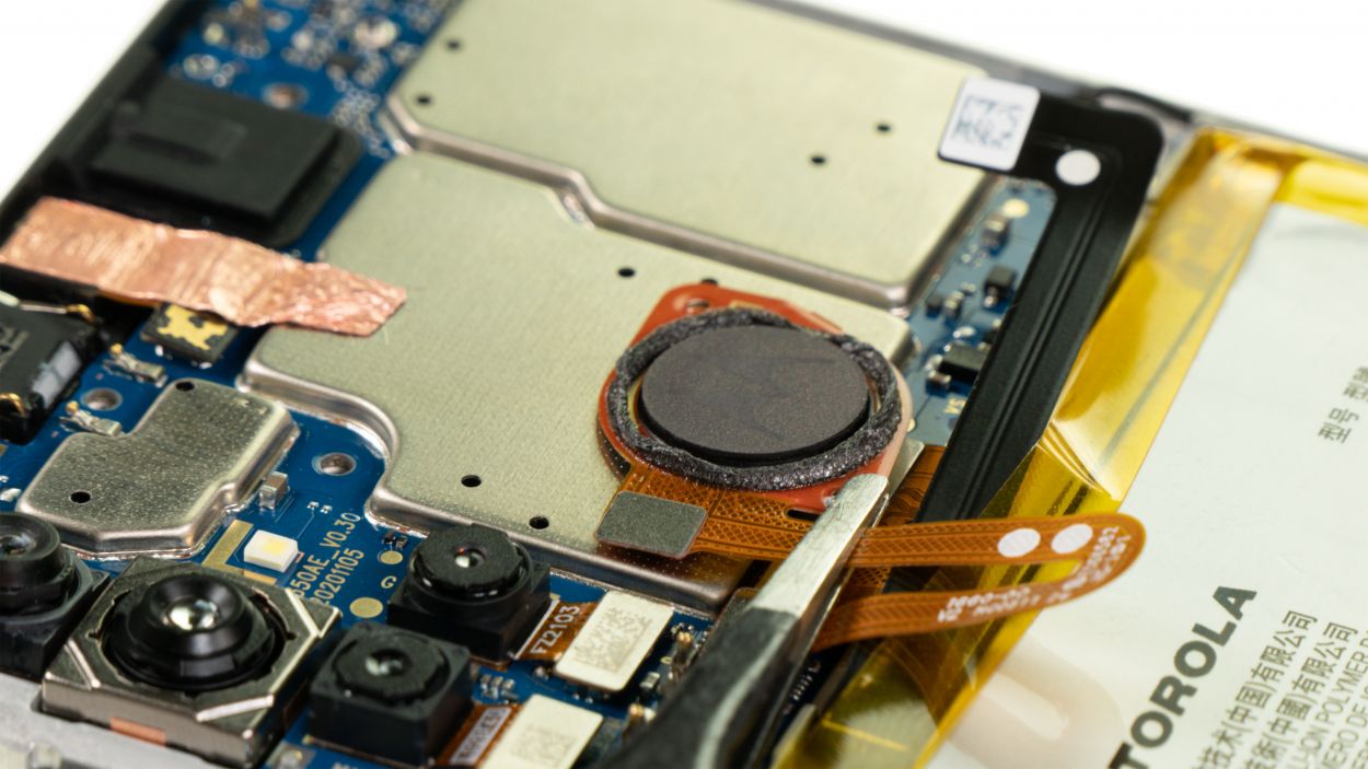
– Gently pop the fingerprint scanner connector off the board using a spudger. Just take your time and be careful—you’re doing great!
Tools Used
Step 10
– Gently lift out the fingerprint scanner from your device and set it aside for now. You’ve got this!
Tools Used
Step 11
Hey there! Just a friendly reminder: when you’re working on that heat-sensitive battery, make sure to warm it up gently from the screen side only. Let’s keep things cool and safe!
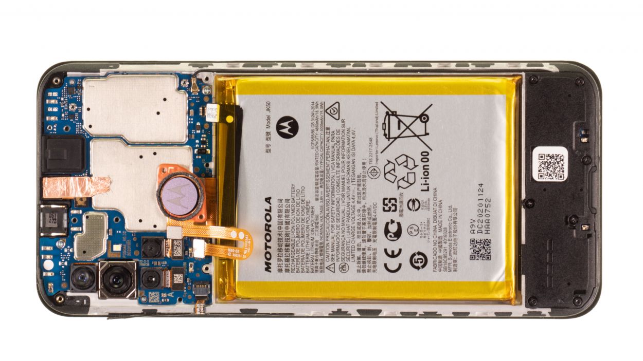
That moto g10 battery’s stuck on there tighter than a drum! Don’t worry, we’ve got this. First, you’ll need to gently warm up the adhesive holding it to the screen. Think of it as giving that battery a nice, warm hug before it’s ready to come out to play. If you need a hand with this step (or any other!), you can always schedule a repair.
Tools Used
- heat gun to heat parts that are glued on so they’re easier to remove.
In most cases, you can also use a hairdryer.” rel=”noopener”>Heat gun
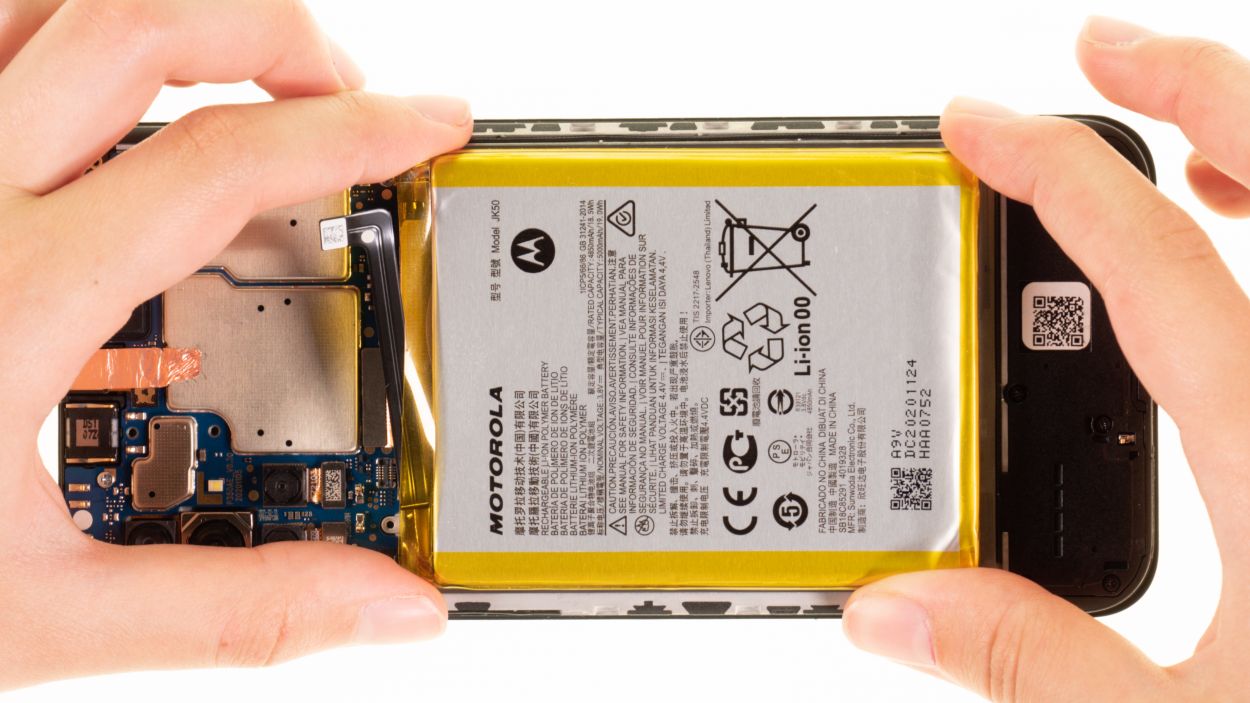
Step 12
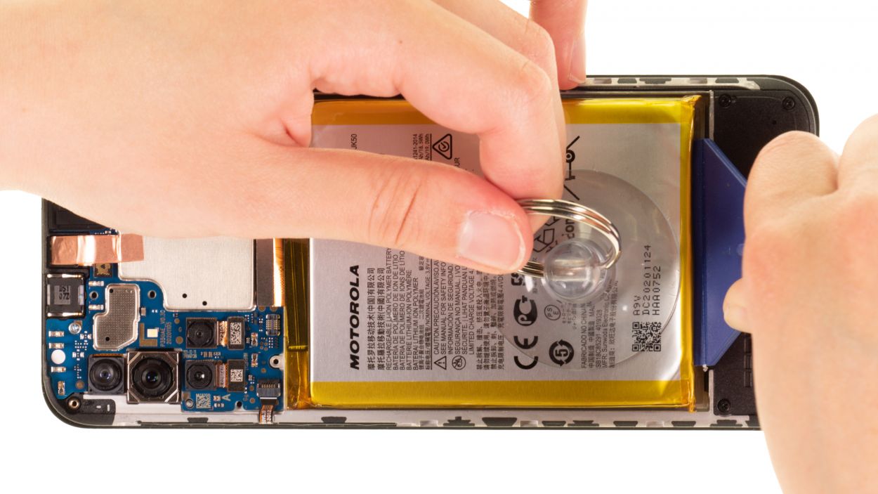

Once the adhesive is nice and toasty, the simplest way to pop that battery out is by using a suction cup along with a handy plastic lever tool. You’ve got this!
– Grab your suction cup and give that battery a gentle hug on its lower edge. Now, with a smooth, upward motion, let’s get that battery lifted!
– Team up your suction cup with a plastic lever tool (we like to call it our ‘battery buddy’) on the lower edge. Push upwards together – it’s a battery-lifting party! If you need help, you can always schedule a repair
Tools Used
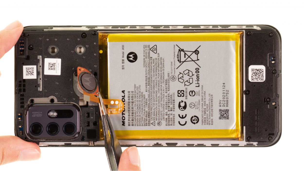
Step 13
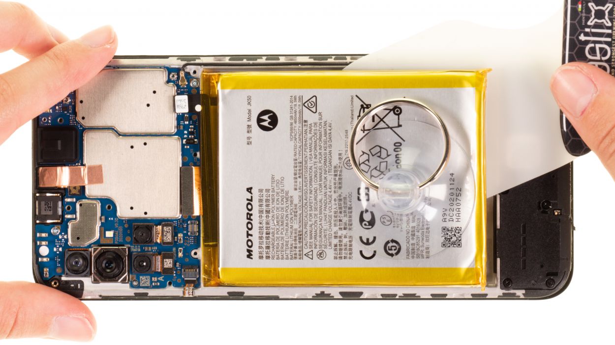

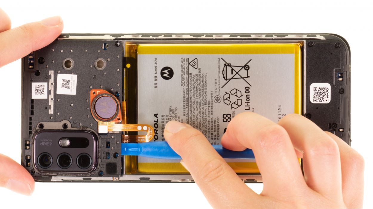
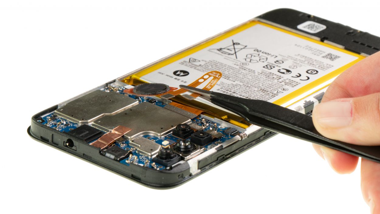
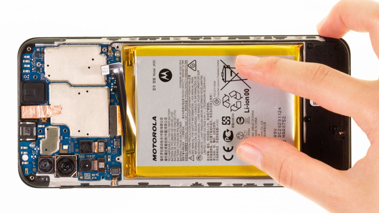
To get that battery loose, try sliding the iPlastix underneath it with a smooth, knife-like motion. It should pop right out! If you need help, you can always schedule a repair.
– Slide that sleek iPlastix tool into the lifted edge and gently work it under the battery, inch by inch, until it’s completely free from the screen unit. You’re doing great!
– Now, simply lift out the battery and say goodbye to that old power source!
Tools Used
- battery? Then the iPlastix with its large blade will help you. The practical assistant is made of flexible, especially sturdy plastic and lies comfortably in the hand. Thanks to its design, you can even get into smaller gaps, for example to lift the screen or to prevent it from sticking together again.” rel=”noopener”>iPlastix Opening Tool
- Battery Spudger
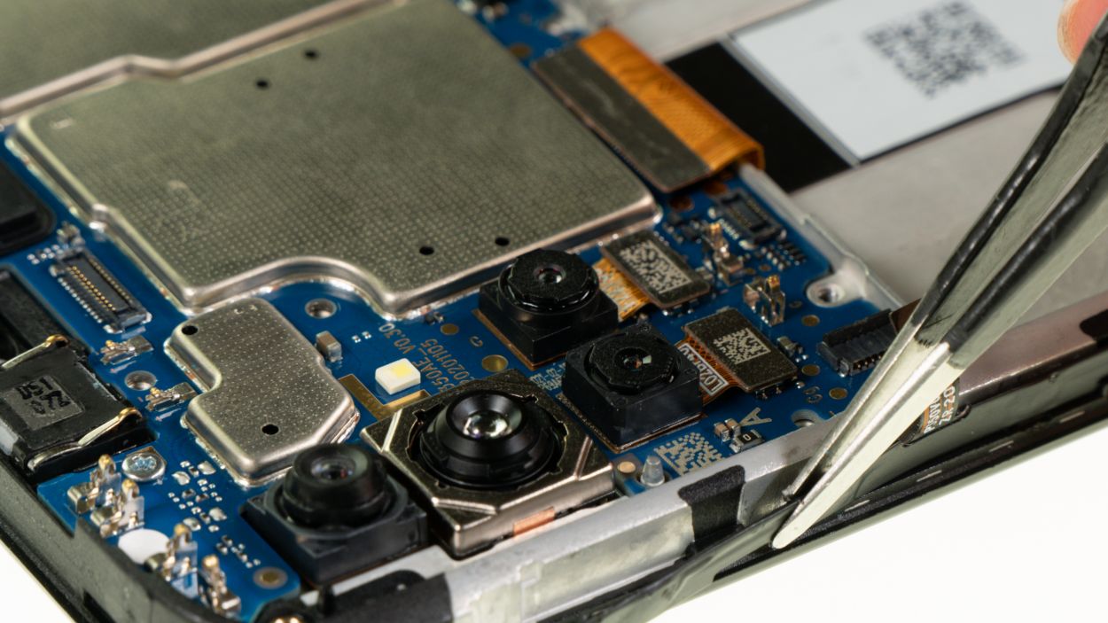
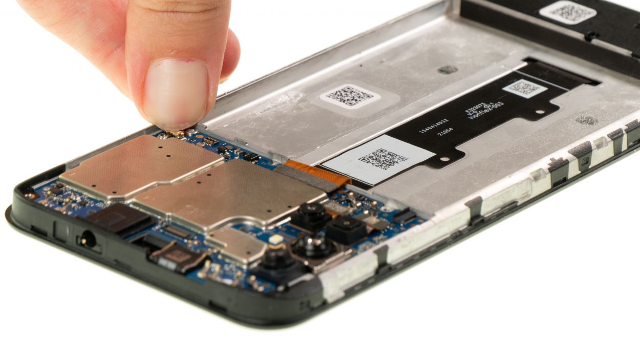
Step 14
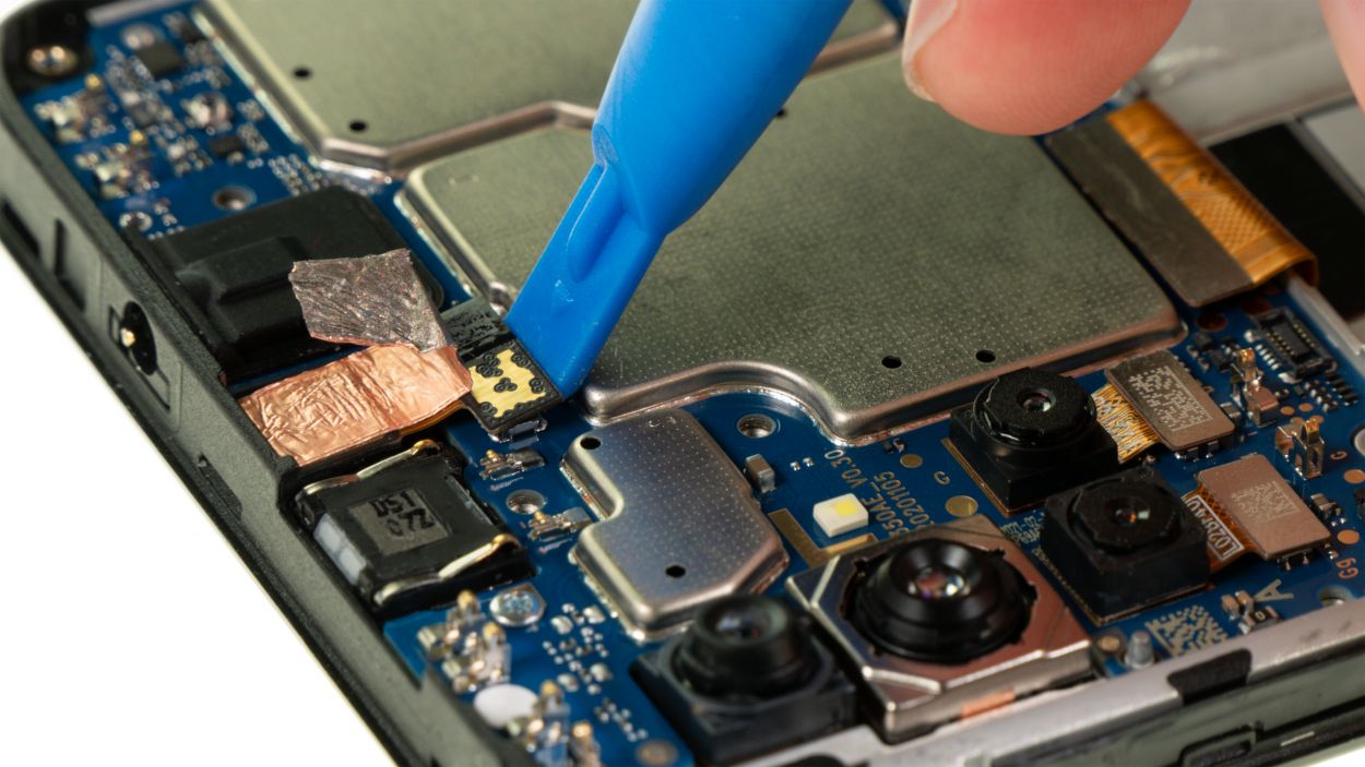
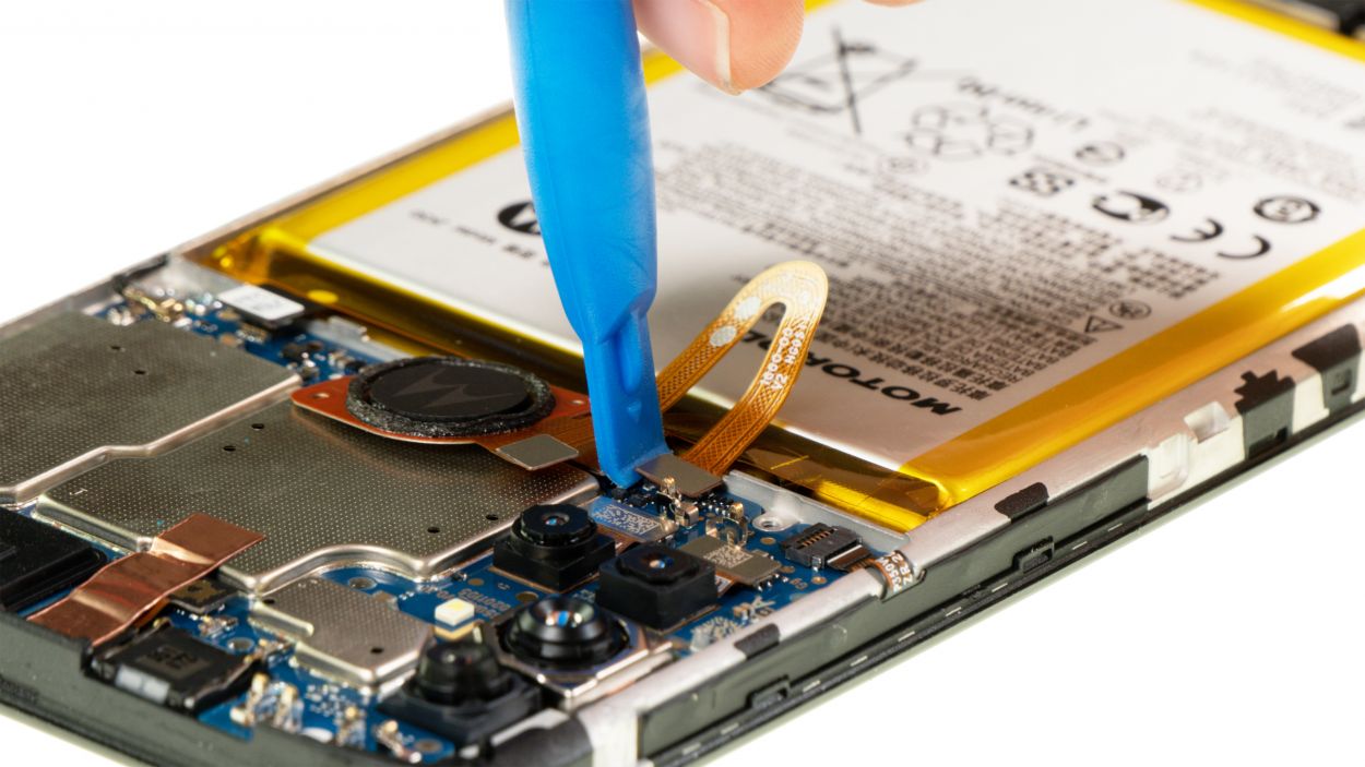
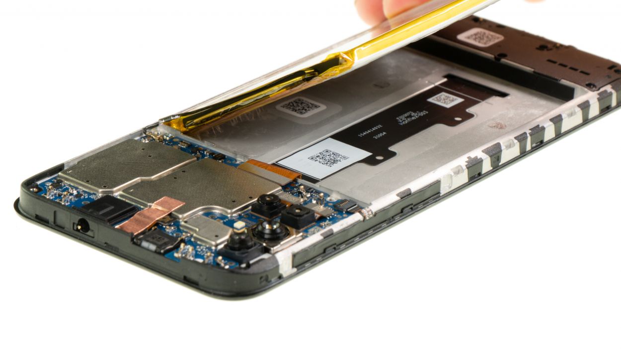
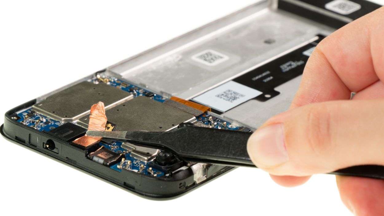
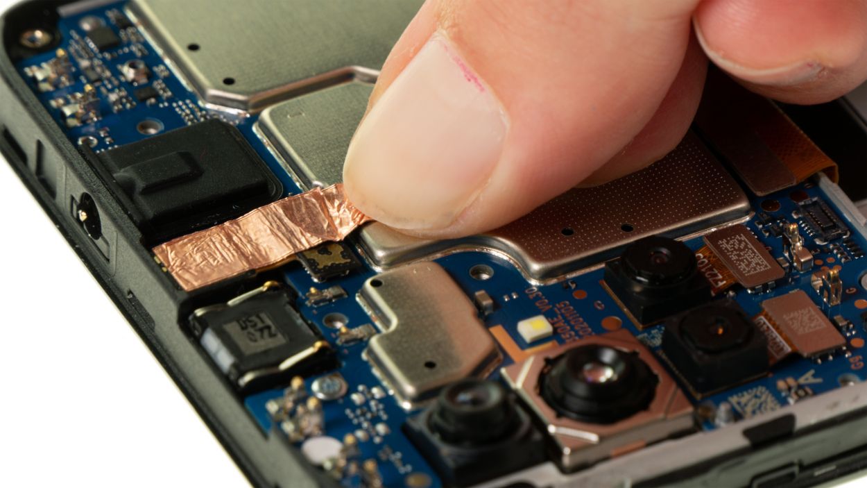
There’s a sleek little copper film hanging out above the front camera and its connector. It’s there to keep things cool, so let’s make sure it stays safe and sound—no damage or removal needed!
– Gently wiggle that copper film with your tweezers to reveal the hidden connector beneath. You’ve got this!
– Next up, give the front camera connector a little nudge and lift it off the board. Easy peasy!
Tools Used
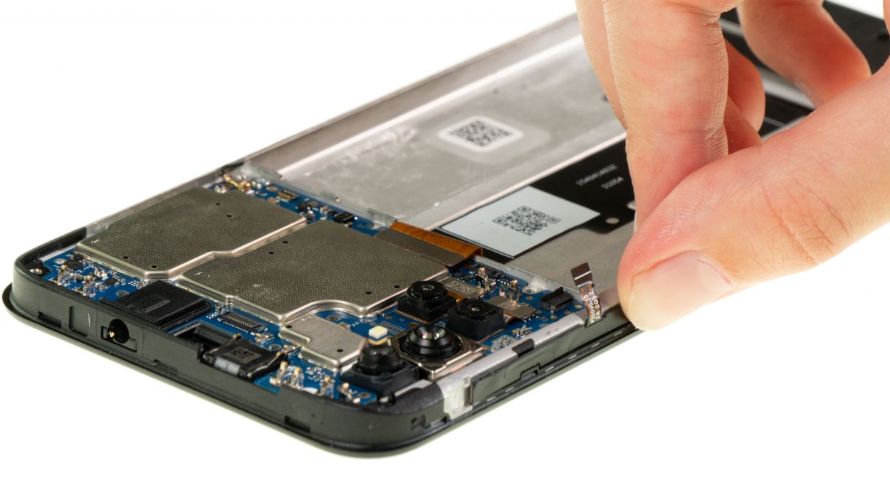
Step 15
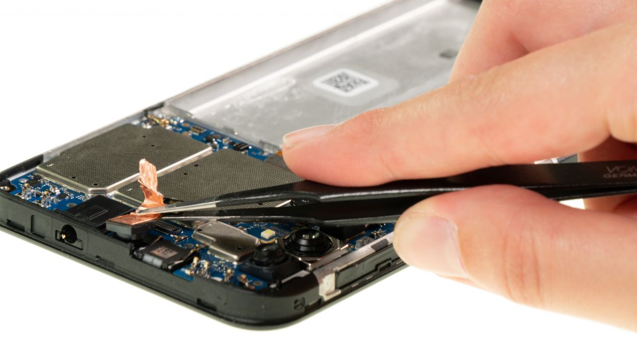
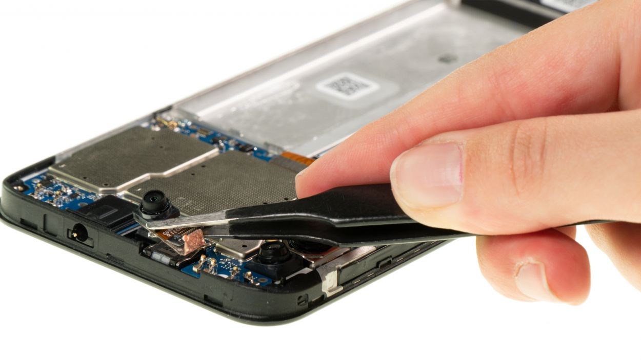
– Take the separated front camera out of the device and put it aside.
Tools Used
Step 16

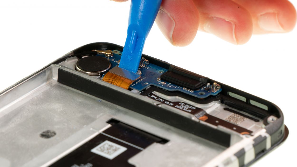
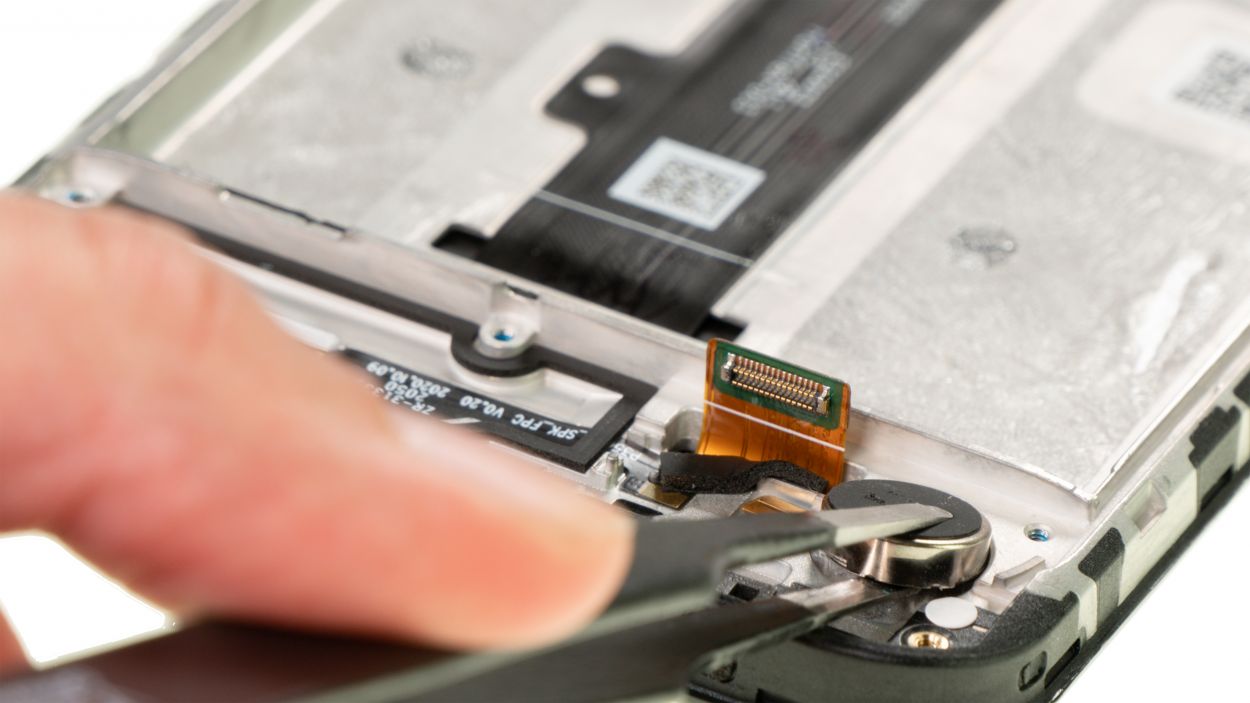
The power button and volume buttons are buddies, connected to the motherboard through the same connector. This connector is snugly locked in place, just like a best friend holding onto your arm during a fun adventure!
– Gently lift the connector lock with a spudger, like you’re giving it a little nudge to say hello.
– Now, slide the short end of the flex cable out from under the lock, as if you’re freeing a little trapped buddy.
Tools Used
Step 17
The flex cable connecting your power and volume buttons is snugly glued to the side of the case frame, all wrapped up in a sleek black protective coating. Just a little heads up as you dive into this repair adventure!
– Give that black-coated flex cable a little warm-up with some hot air – just a quick blast should do the trick!
– Now, gently pry the flex cable away from the case frame, one piece at a time, using a flat, sturdy tool. Tweezers work wonders for this job!
Tools Used
- heat gun to heat parts that are glued on so they’re easier to remove.
In most cases, you can also use a hairdryer.” rel=”noopener”>Heat gun - Piergiacomi Tweezers 2a SA ESD
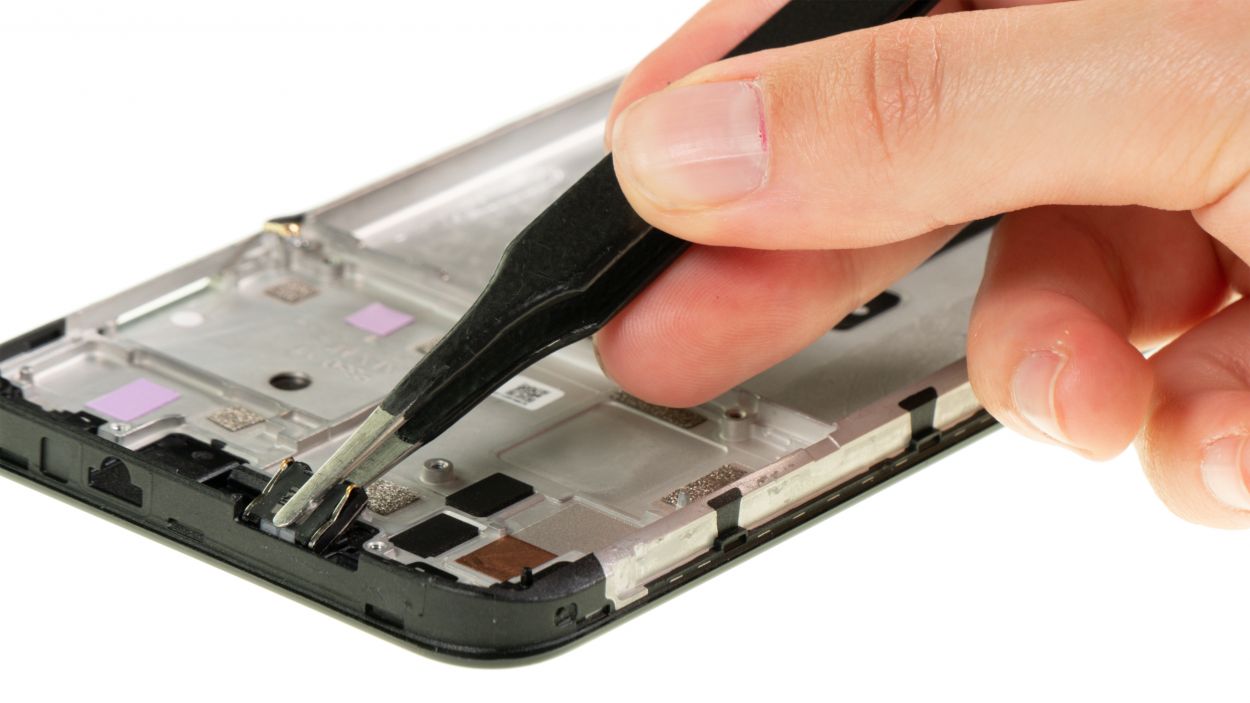
Step 18

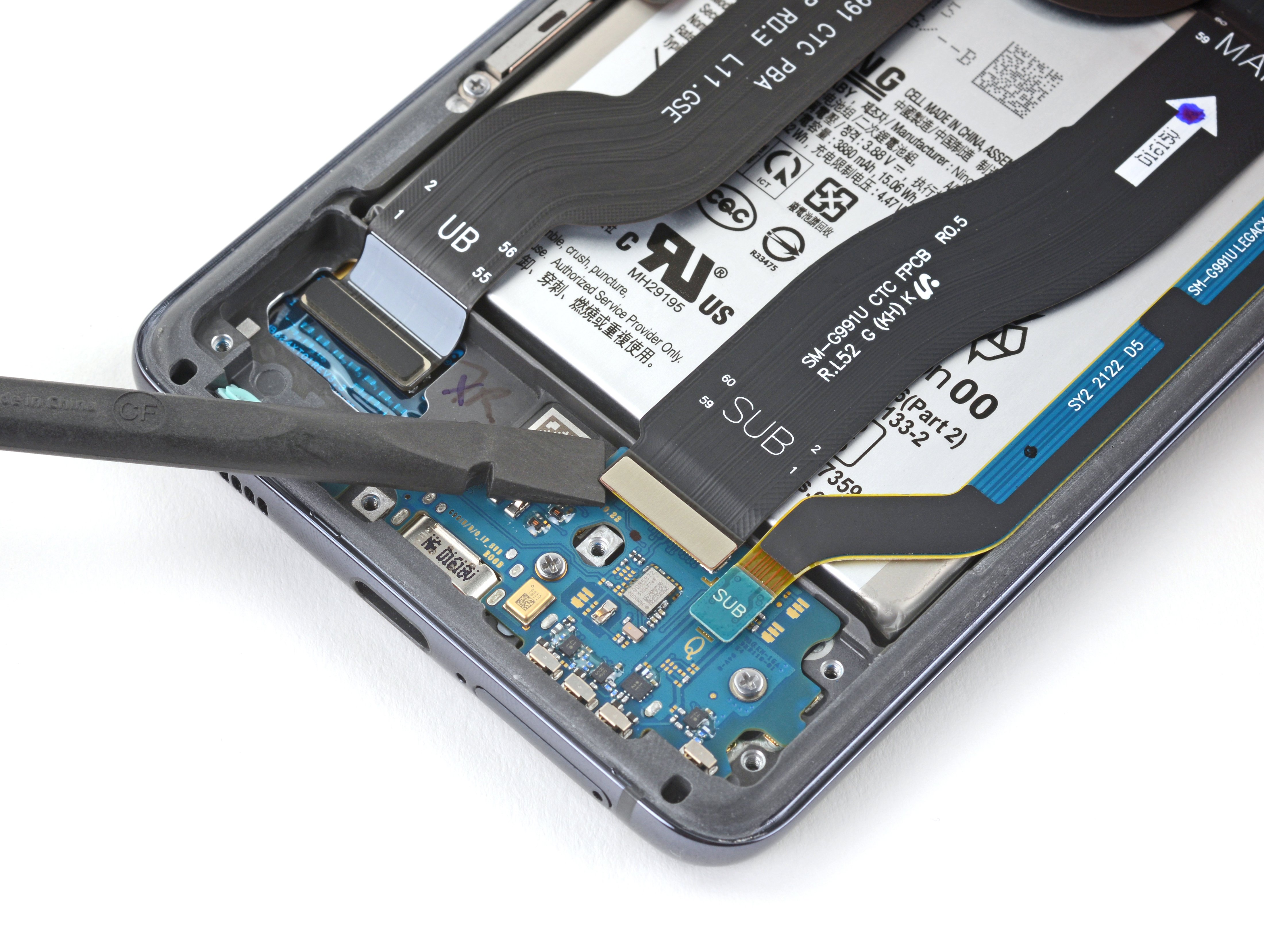
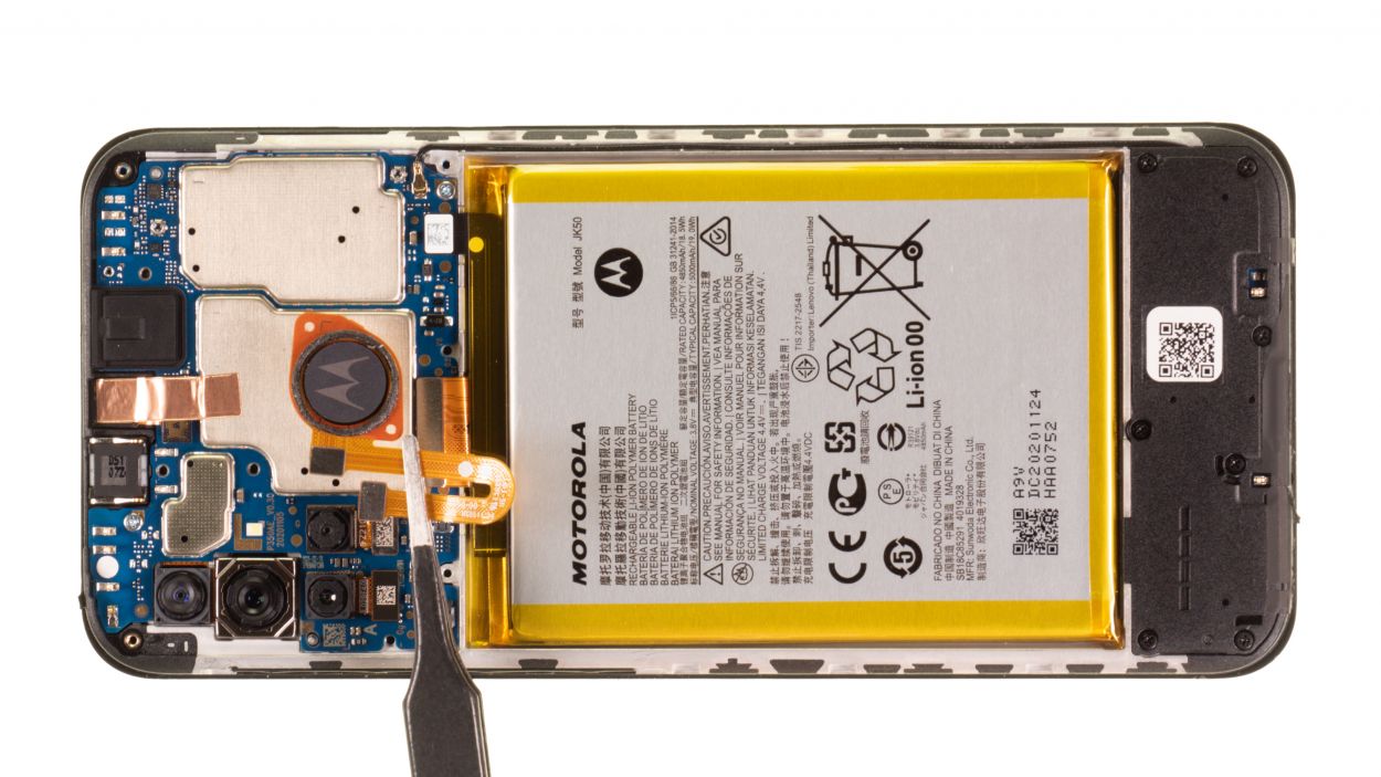
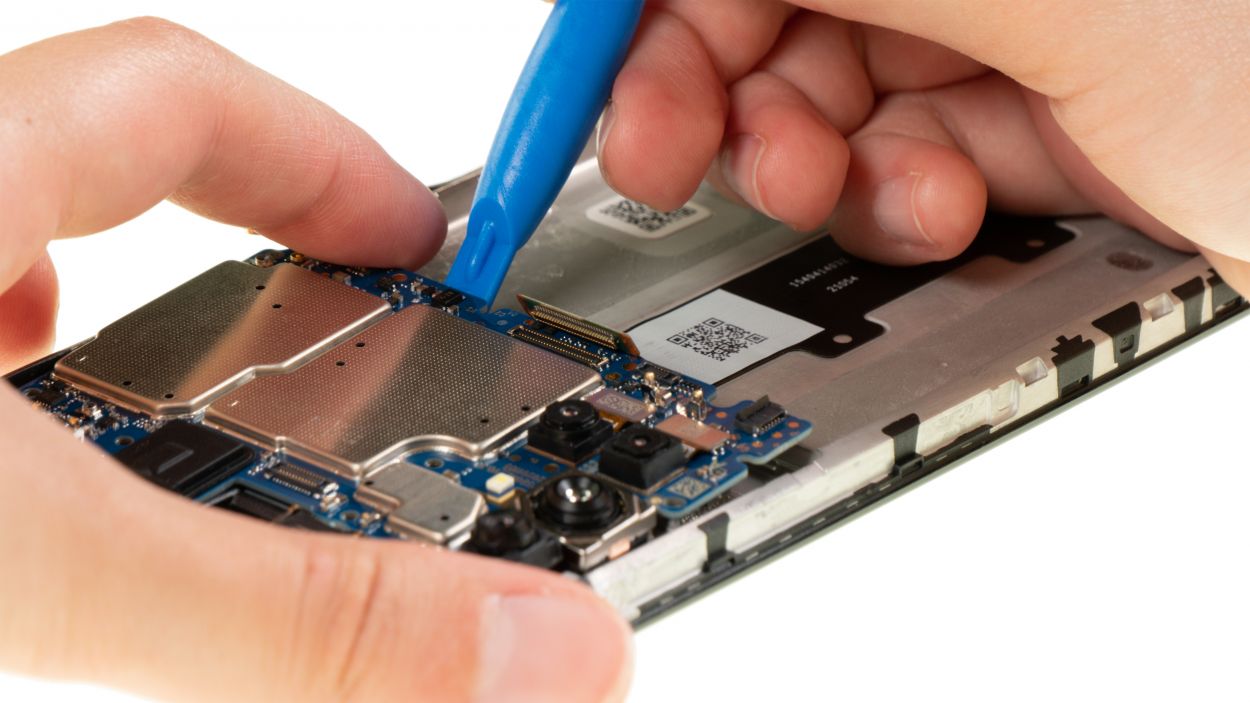
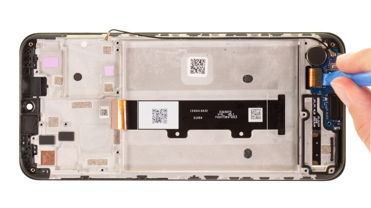
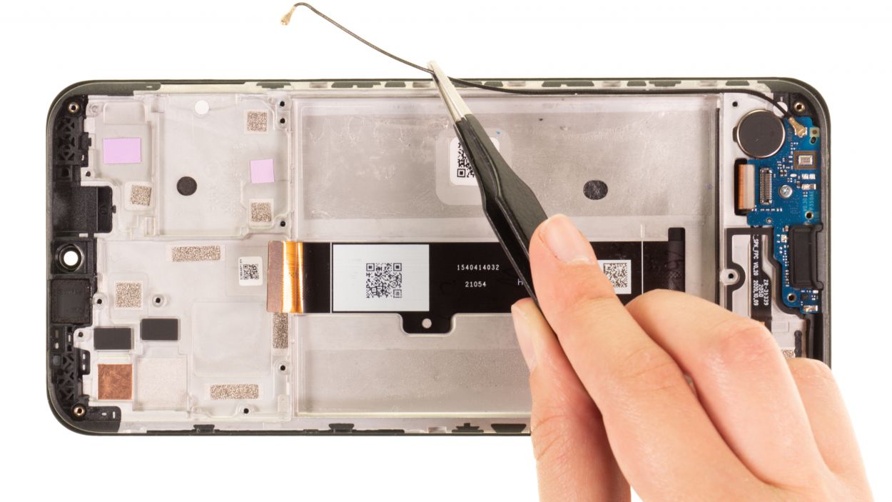
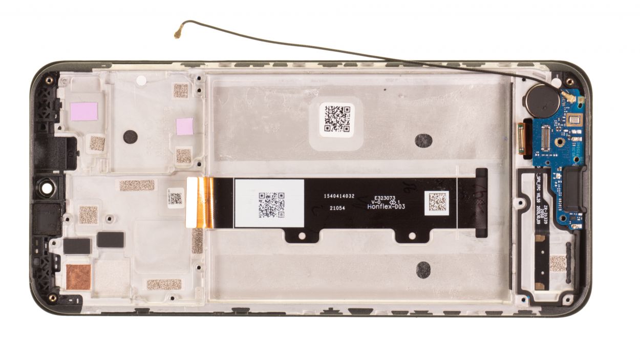
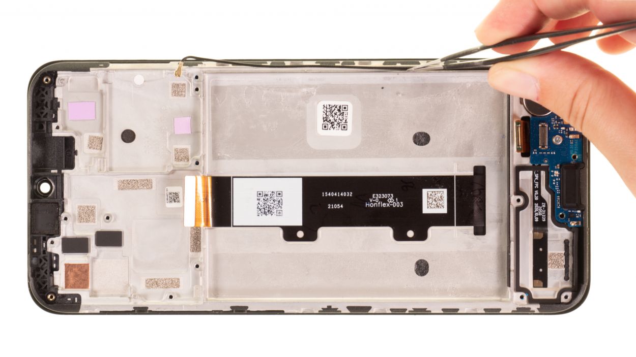
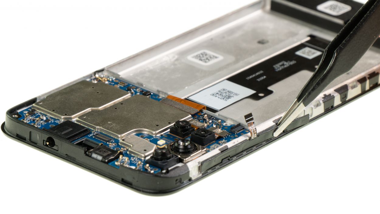
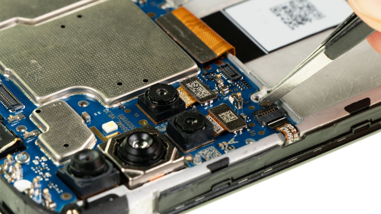
The last few connectors still hanging out on the motherboard are the screen connector and the antenna cable. Keep your spirits high, you’re almost there!
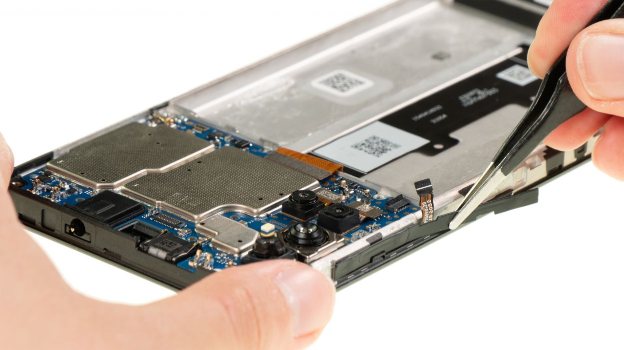
– Gently detach the last two connectors from the motherboard. A trusty pair of tweezers works wonders for that tiny antenna cable connector!
Tools Used
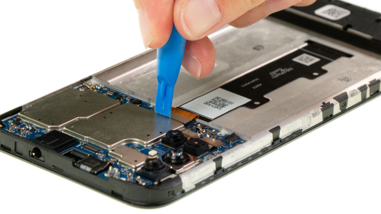
Step 19
2 × 2.9 mm Phillips
– Gently unscrew those two Phillips screws from the motherboard—let’s get that thing loose!
– Now, give it a cozy spot on the magnetic pad. It deserves a nice place to rest!
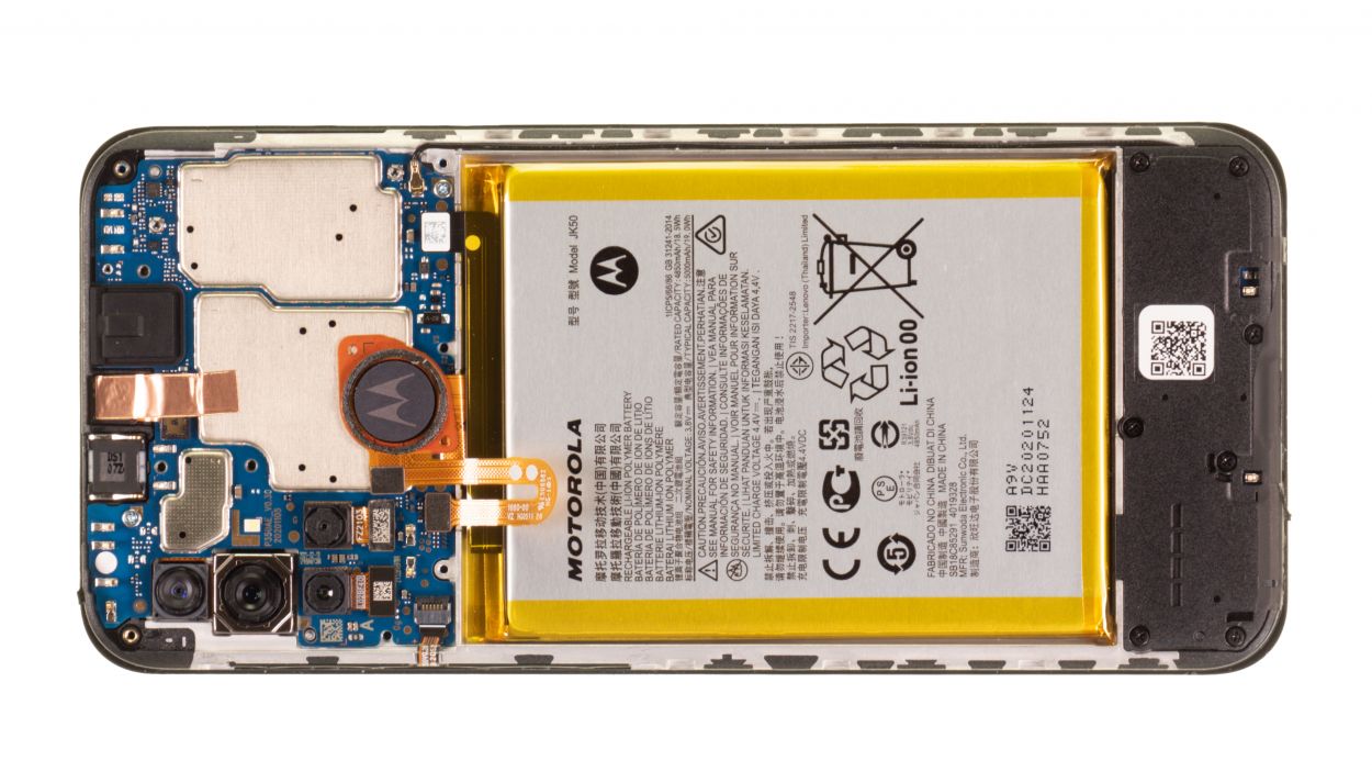
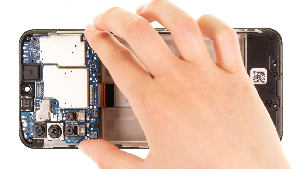
Step 20
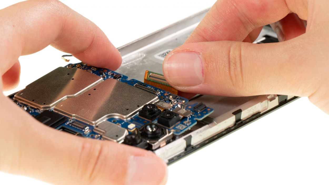
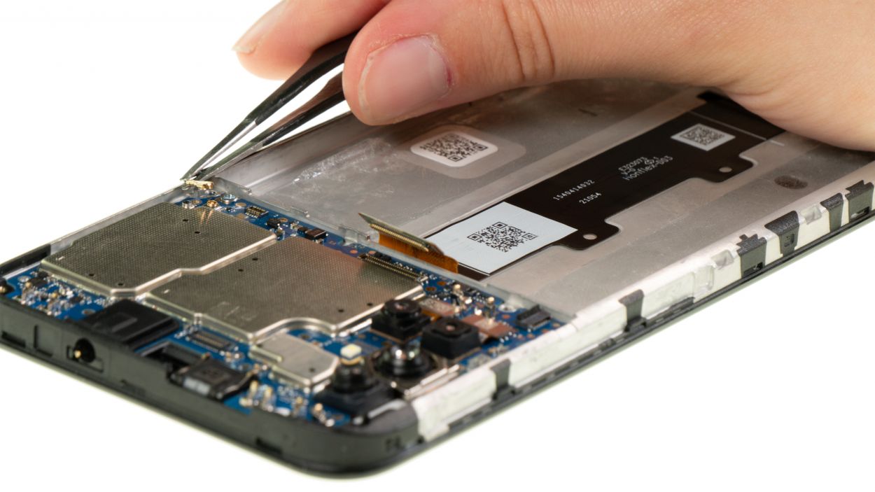
Hey there, champ! Gently move those screen and antenna cables out of the way while you’re removing the motherboard. We don’t want any accidental cable-related mishaps, alright? Keep those little guys safe and sound! If you need a hand, you can always schedule a repair
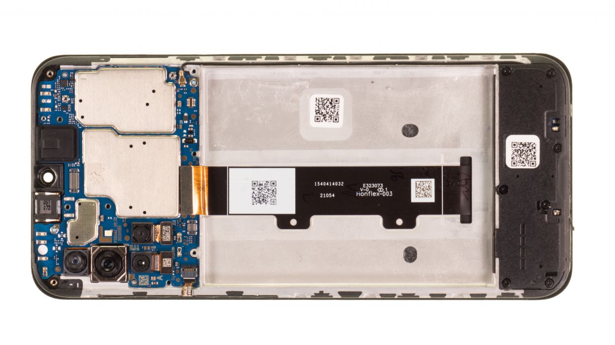
– Gently nudge the unscrewed motherboard upwards to set it free from its cozy spot.
– Lift it out of the device and place it somewhere safe for now.
Tools Used

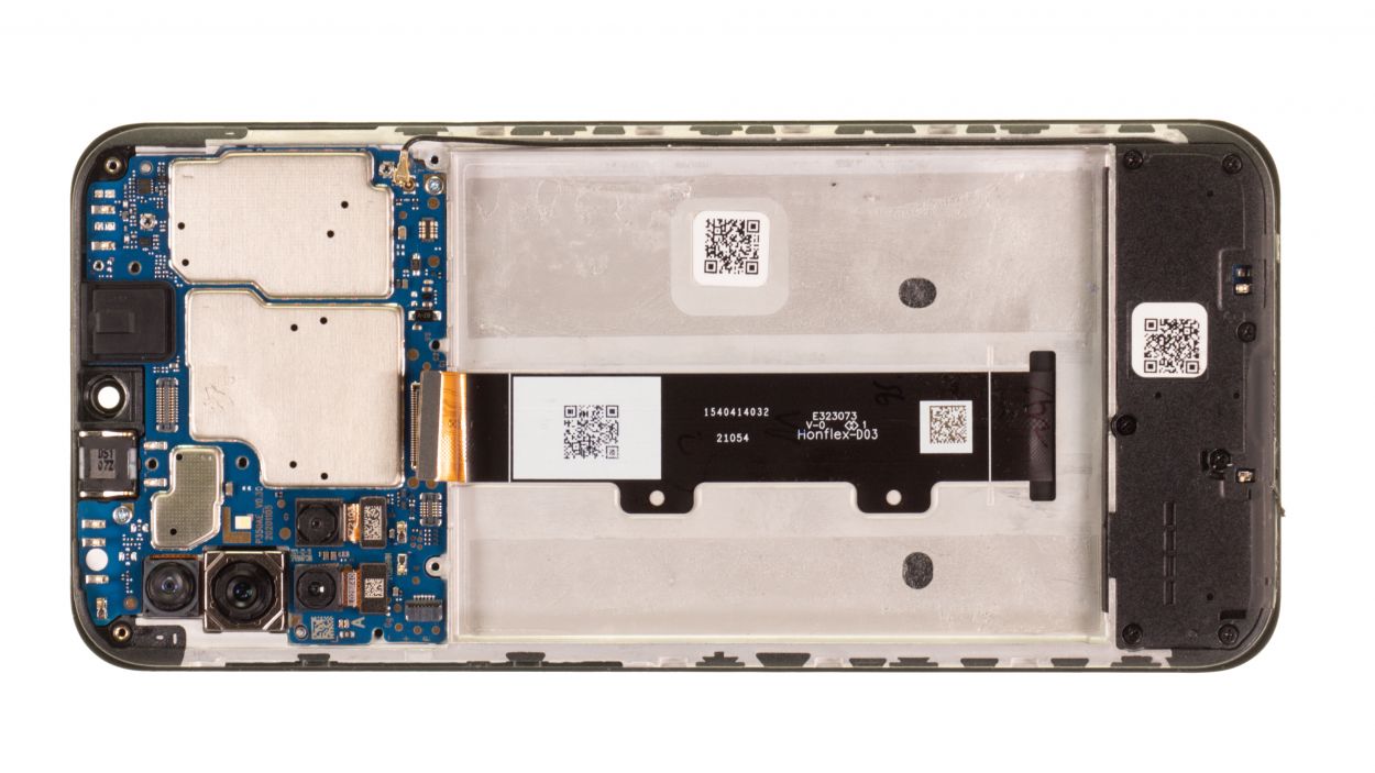
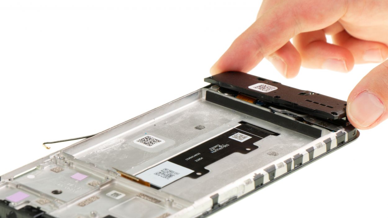
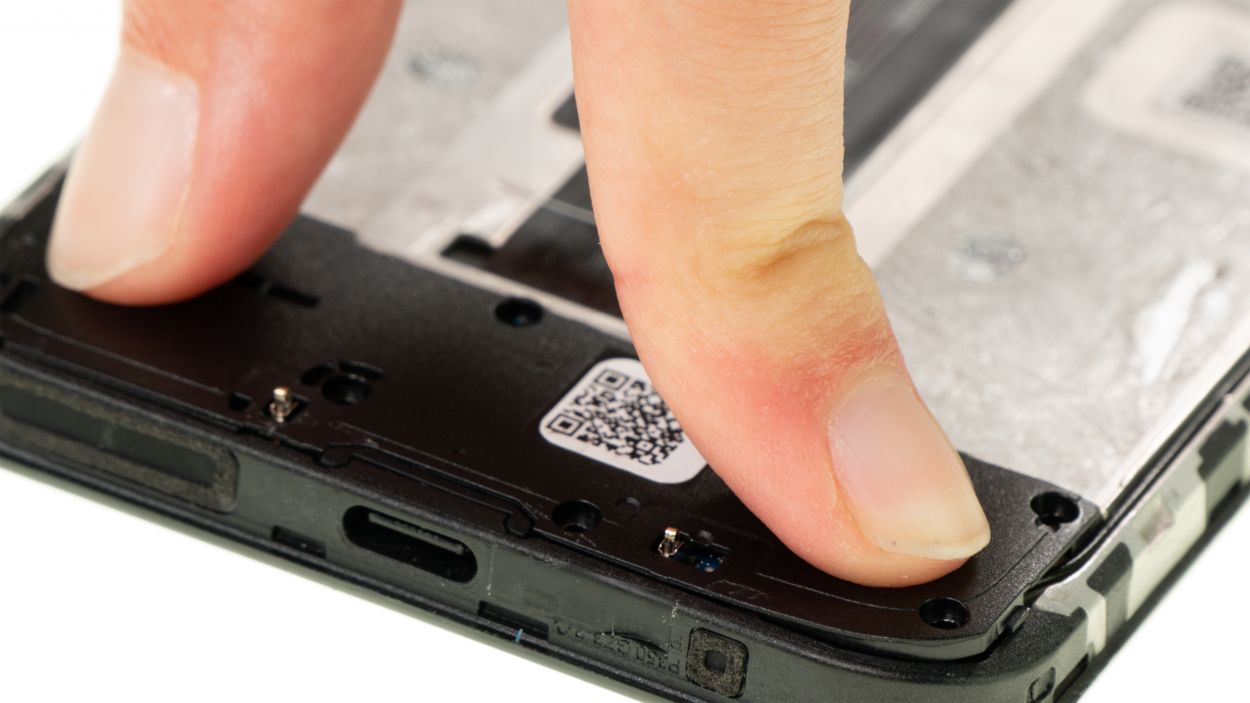
Step 22
7 × 3.3 mm Phillips
– Let’s get those seven Phillips screws out of the speaker module! Easy peasy!
– Give those screws a safe place to hang out – pop ’em on the magnetic pad.
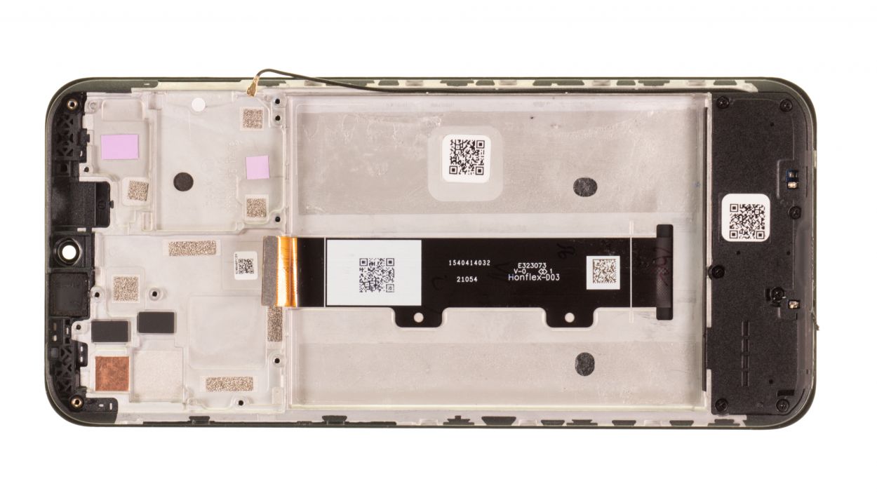
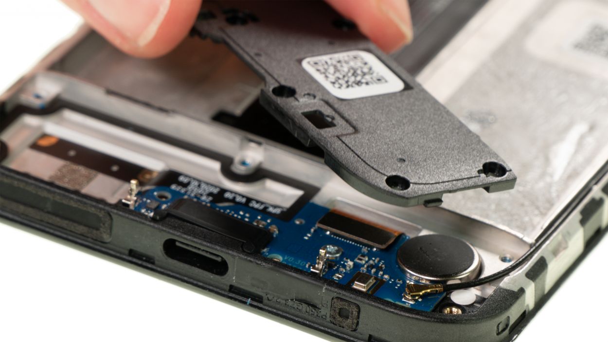
Step 23
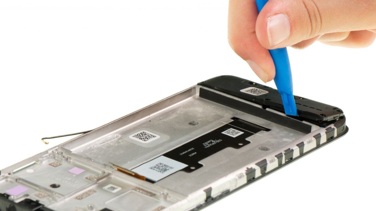
That tiny notch on the speaker’s guide? It’s your secret weapon for perfect tool placement! Smooth sailing from here on out.
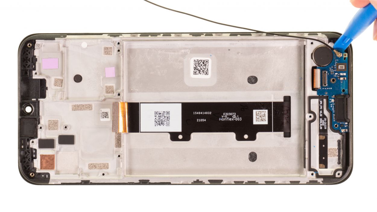
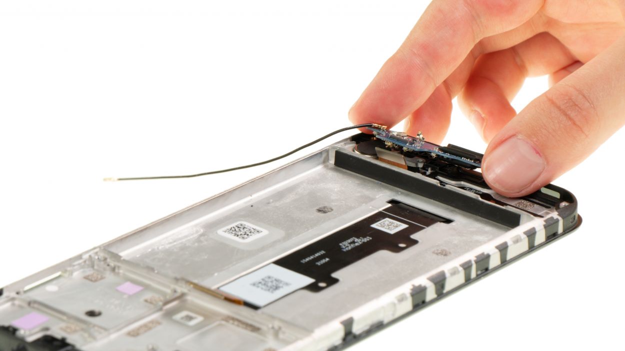
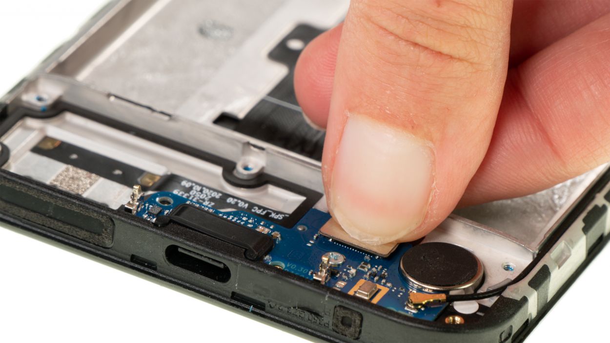
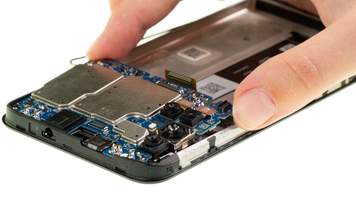
Step 24
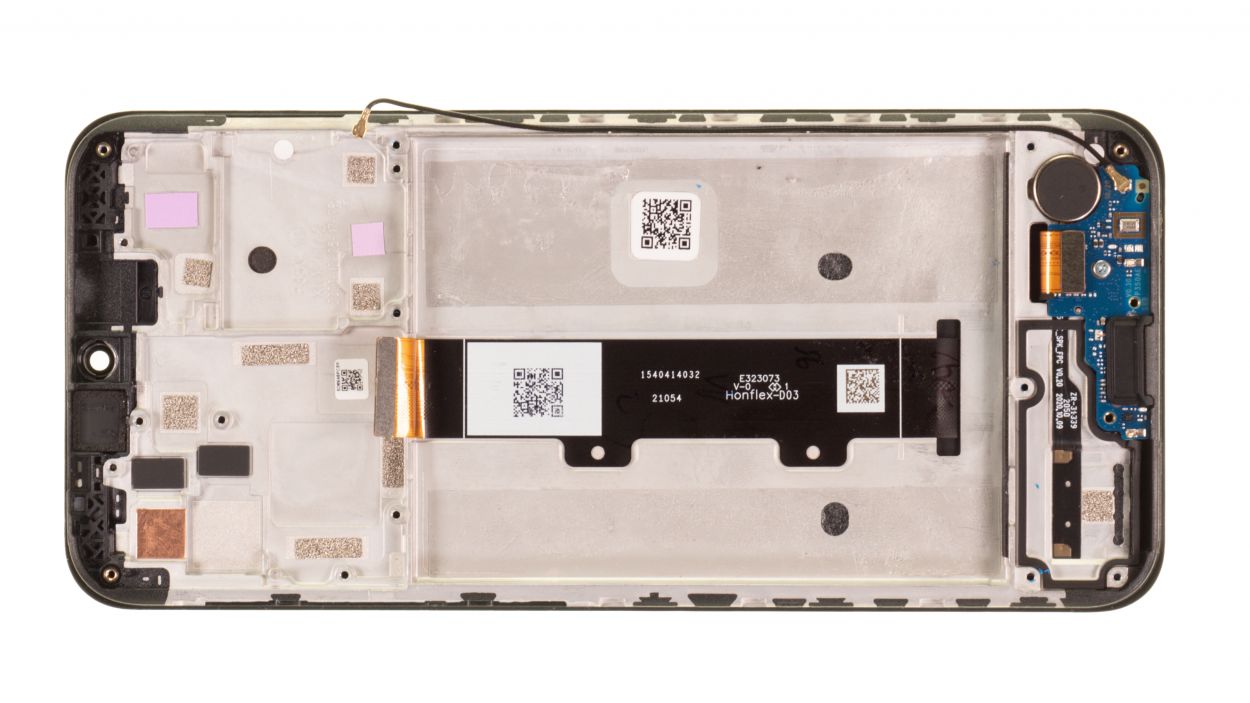
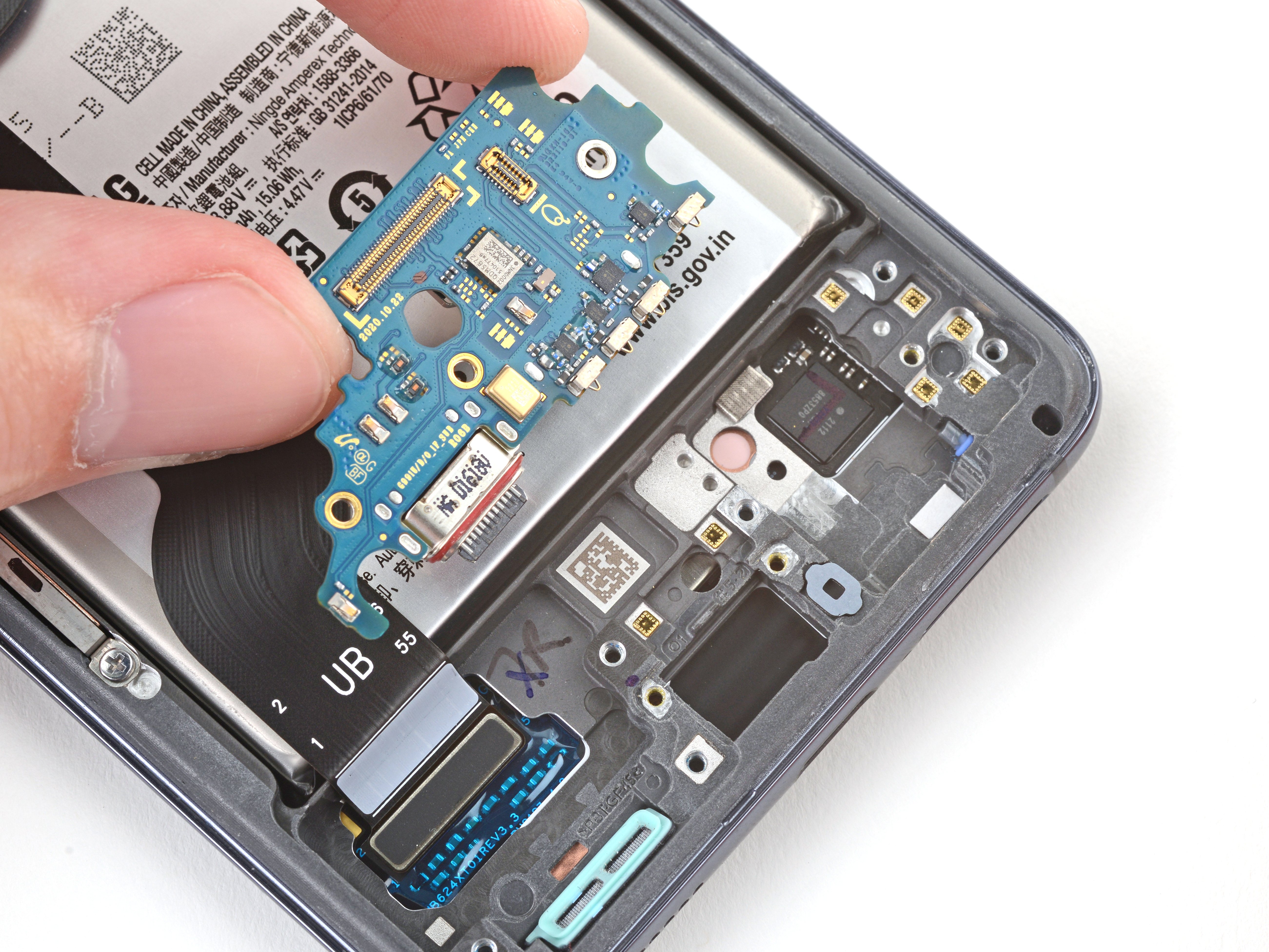
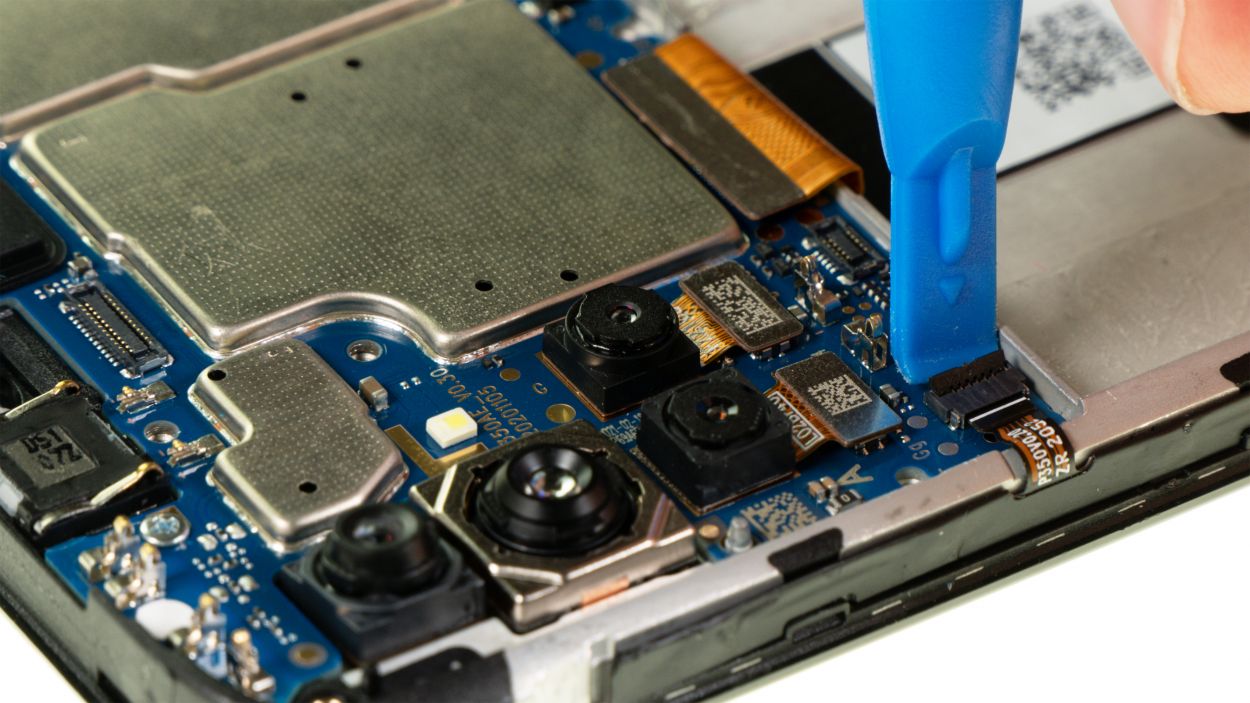
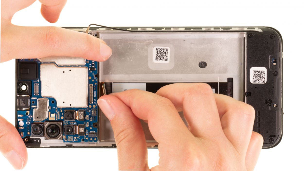
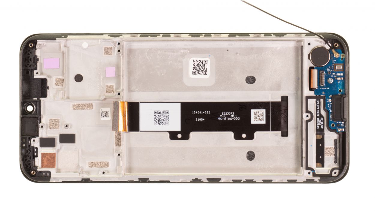
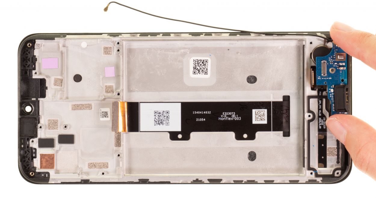
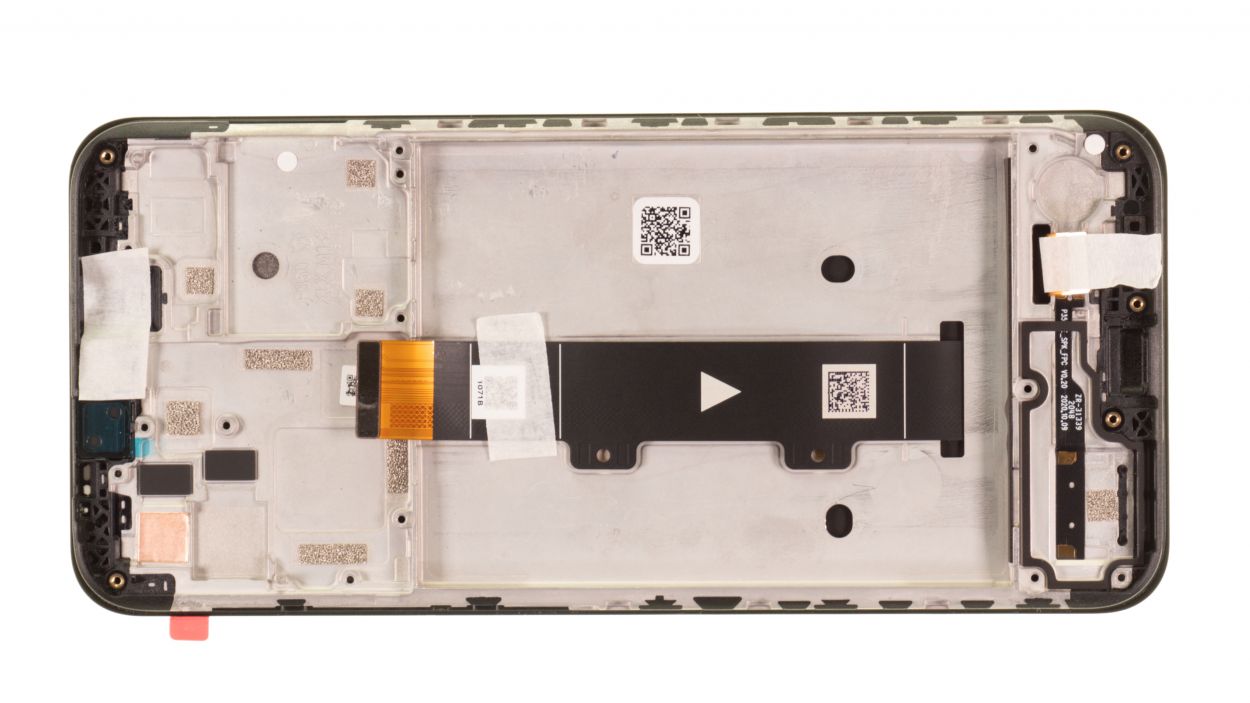
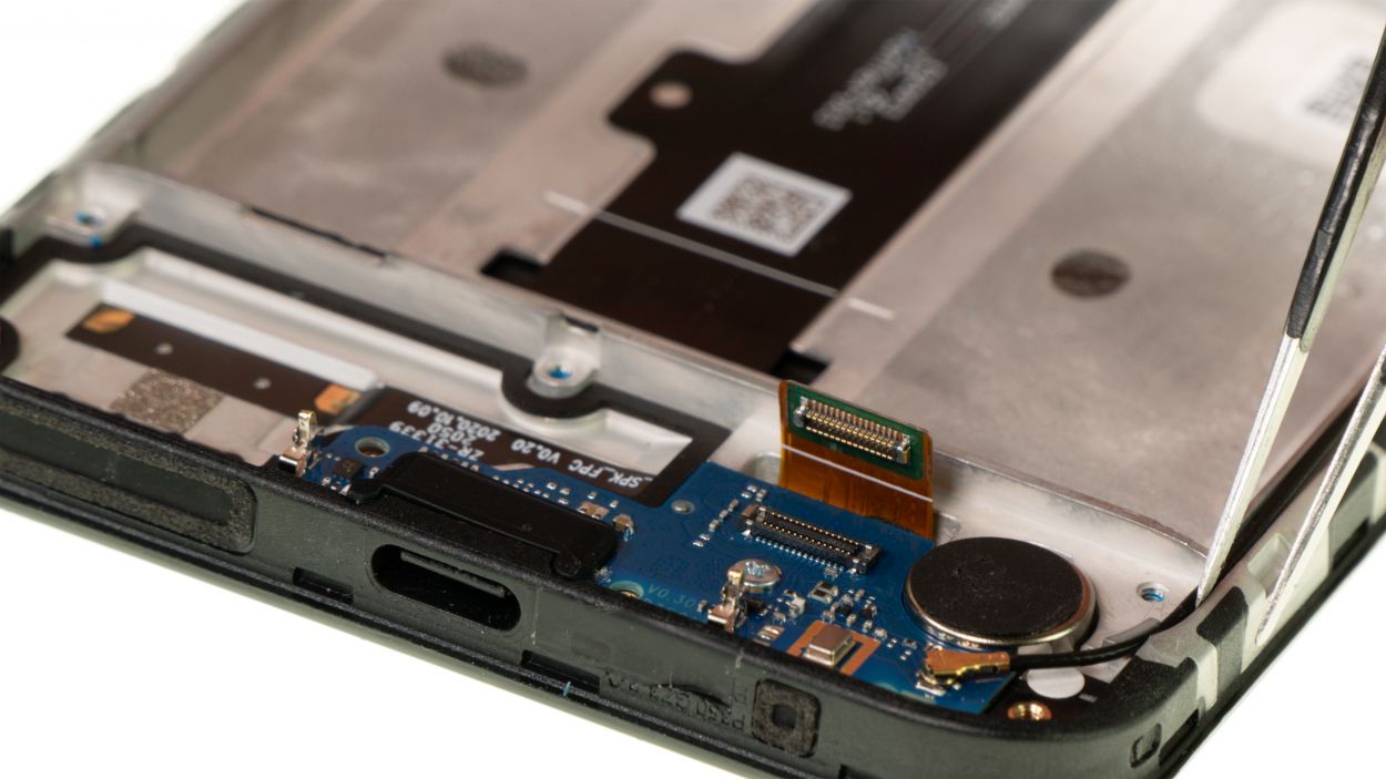
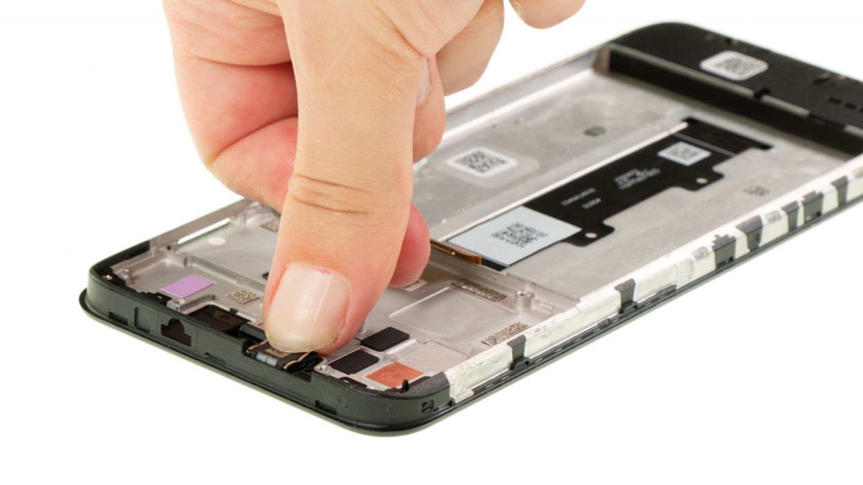
The USB board’s flex cable is cleverly tucked away in the screen unit of the Moto G10, creating a seamless connection between the USB and the motherboard. It’s like they’re best buddies, working together to keep your device running smoothly!
– Gently pry the USB board connector apart using a spudger, taking care to avoid any damage. You’ve got this!
Tools Used
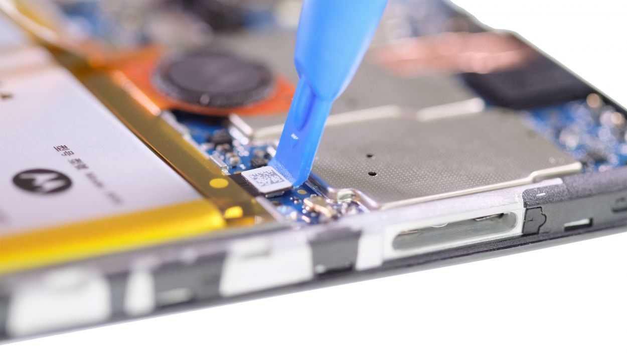
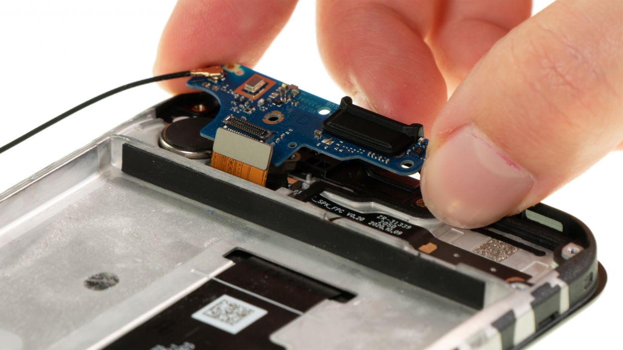
Step 26
1 × 2.9 mm Phillips
– Gently unscrew the lone Phillips screw holding the USB board in place. It’s like giving it a little massage!
– Once it’s free, let it chill on the magnetic pad. It’s a cozy spot for it to relax.
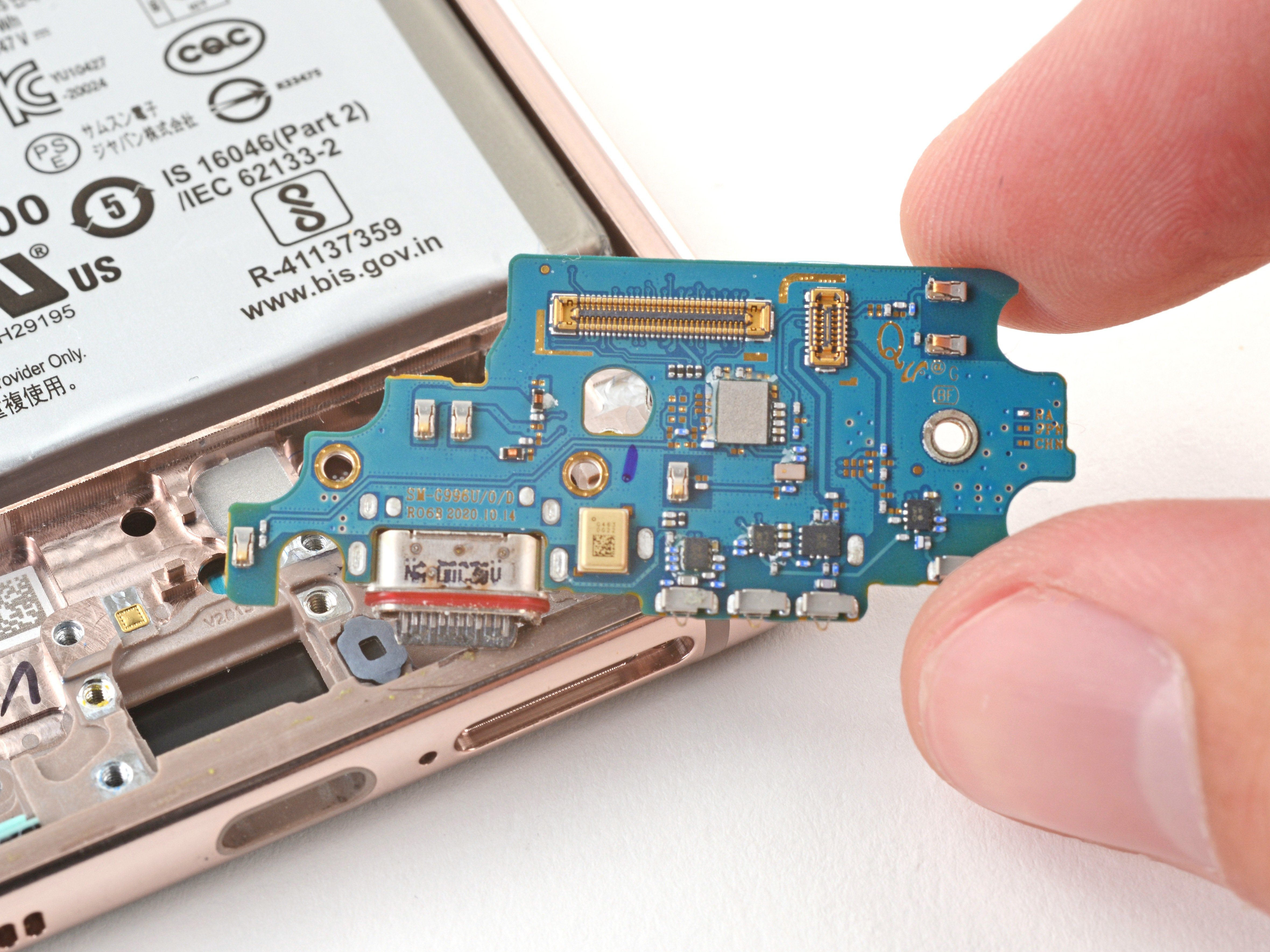
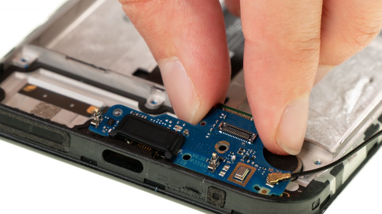
Step 27
– Time to set that USB board free! Carefully pry it upwards to release it from its guide.
– Now, gently pull it out of the device and set it aside – you won’t be needing it for a bit.
Tools Used
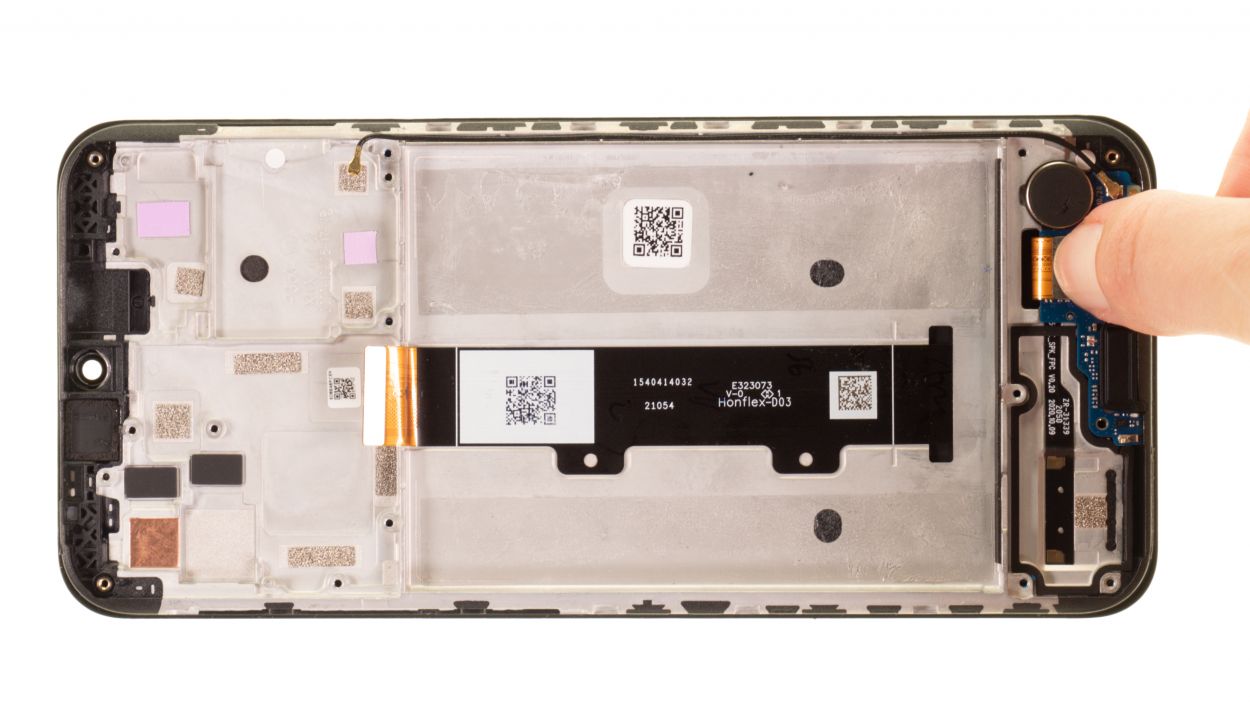
Step 28
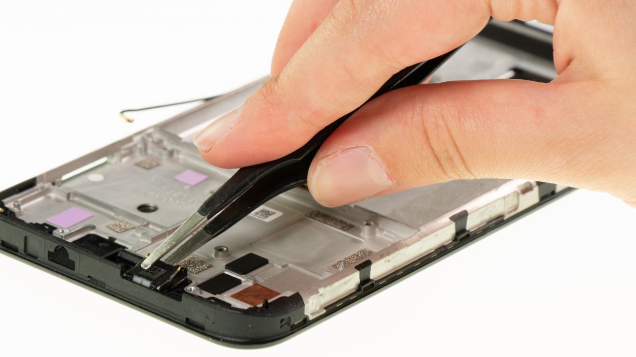
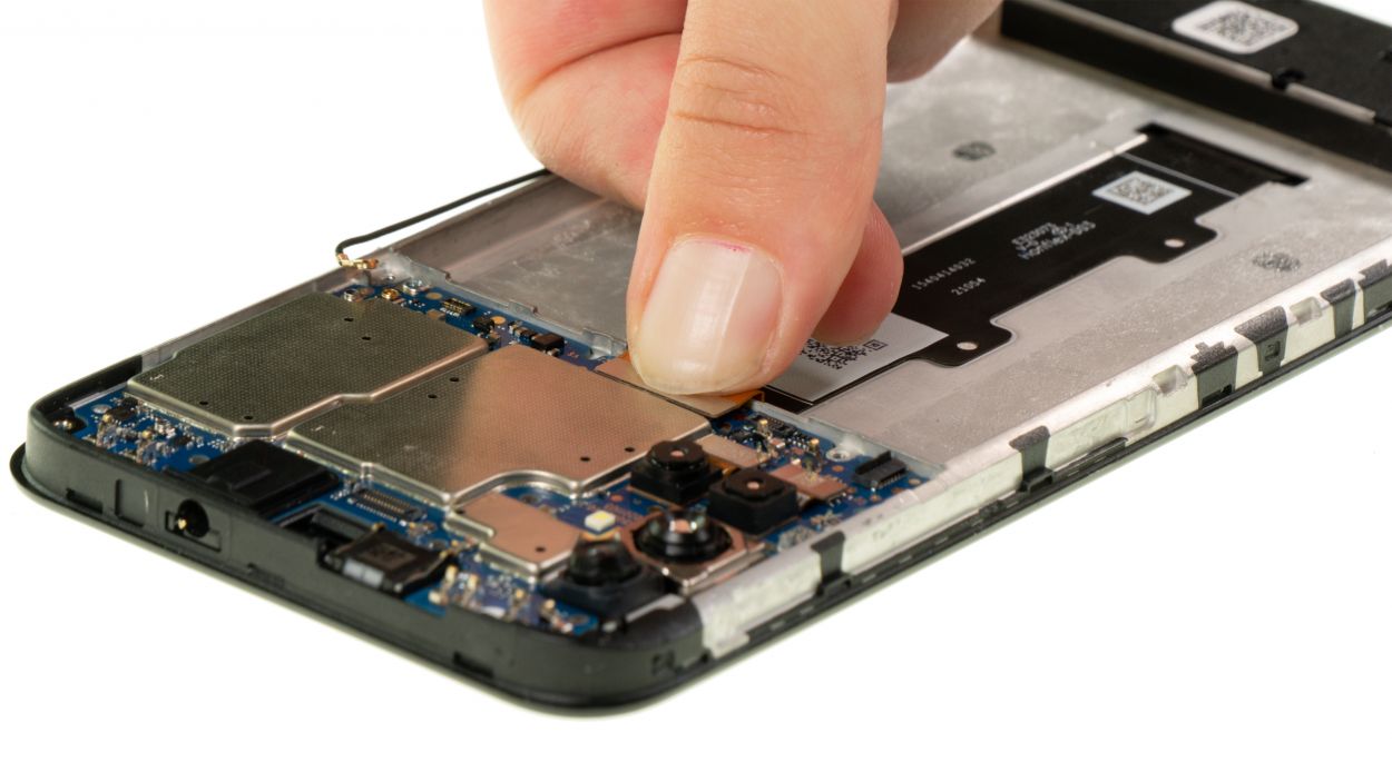
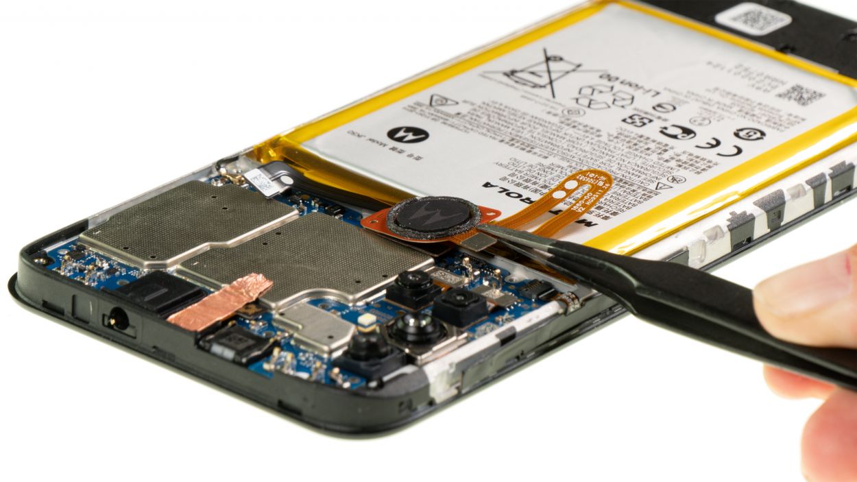
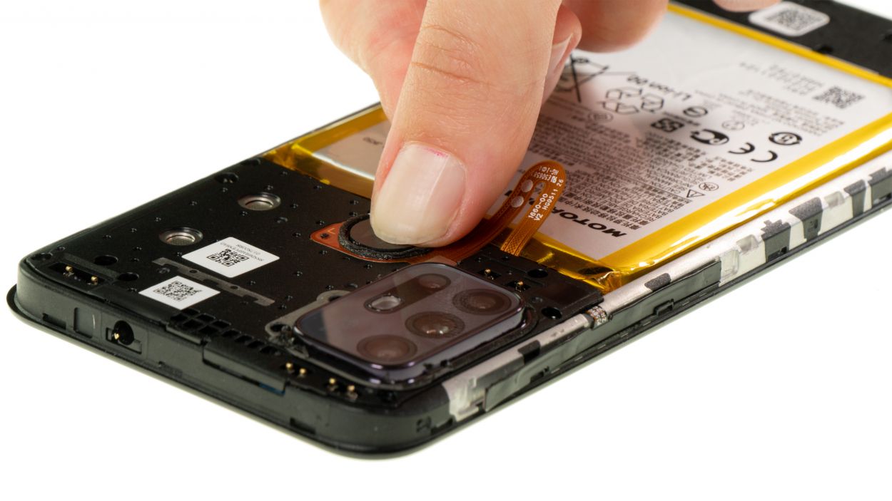
The vibration motor is stuck on there pretty well. To help loosen it up a bit, try giving it a gentle blast of hot air first. It’ll make your job a whole lot easier!
– Gently pull out the vibration motor from the screen unit using a pair of tweezers. Take your time and be careful—it’s a little tricky, but you’ve got this!
Tools Used
- heat gun to heat parts that are glued on so they’re easier to remove.
In most cases, you can also use a hairdryer.” rel=”noopener”>Heat gun - Piergiacomi Tweezers 2a SA ESD
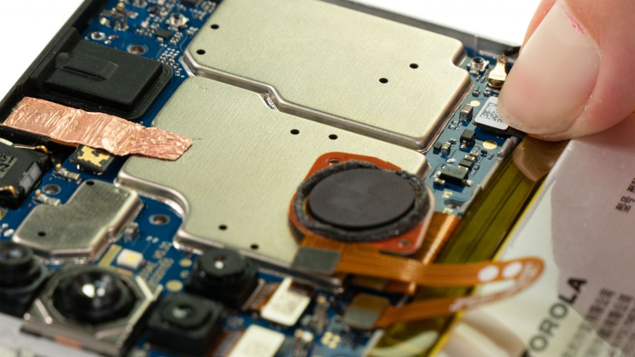
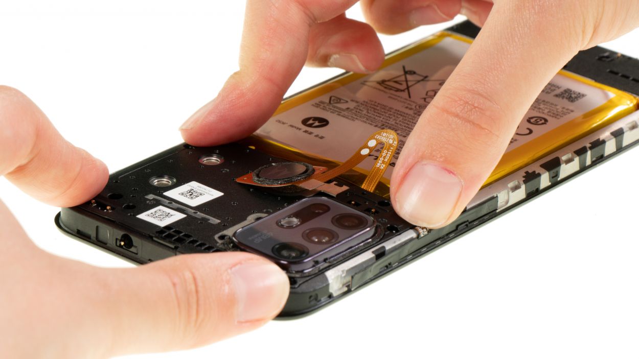
Step 29
The replacement screen for your Motorola moto g10 comes ready for action, but it’s not pre-installed. That means it’s time to roll up your sleeves and transfer all the components to the shiny new screen. If you need help, you can always schedule a repair.
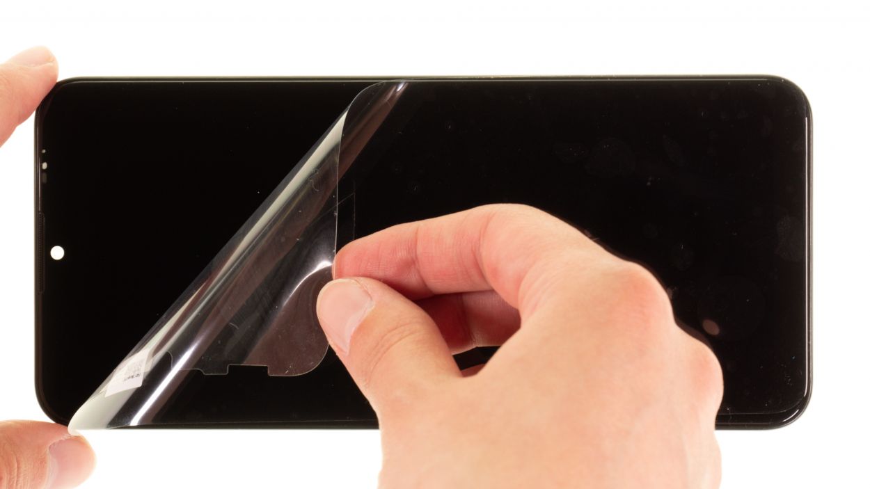
– Before diving into the reassembly party, make sure to peel away all those protective films and seals from the inside of the new screen. It’s like unwrapping a gift, but for your device!
– Feel free to keep that protective film on the screen glass until you wrap up the repair. It’s there to keep things safe and sound until you’re all done!
Tools Used
Step 30
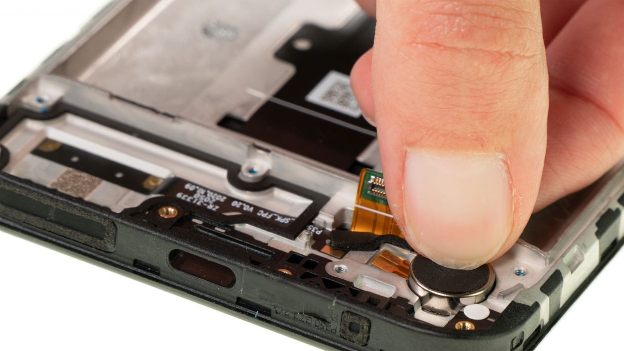
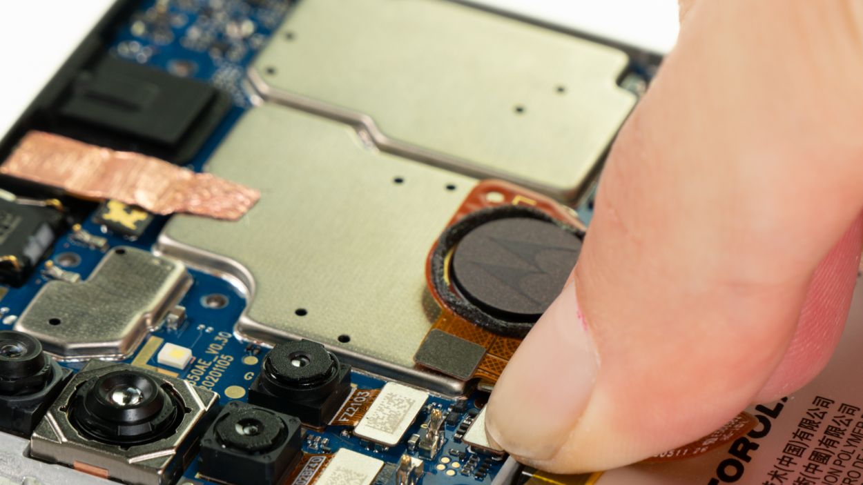
– Put the vibration motor back in its original position and press it lightly.
Tools Used
Step 31
To make sure the USB board fits just right, you’ll want to gently nudge the USB socket into its cozy little spot in the case frame. A little tip? Angle the board slightly for a smoother fit. If you need help, you can always schedule a repair!
– Carefully place the board back into its cozy spot in the screen unit.
Step 32
1 × 2.9 mm Phillips
Hey, screw-tastic! When you’re screwing components into place, make sure to keep those screws in check. A too-long screw in the wrong spot could mean screen damage – and nobody wants that! So, stay focused and get those screws in the right place.
– Secure the USB board with a single Phillips screw.
Tools Used
Step 33
– Use tweezers to carefully push the antenna cable back into its guide at the edge of the case.
Tools Used
Step 34
Connector caution! Don’t force those connections, or you might end up with a busted component. Take it easy, and you’ll be golden!
– Gently press down on the USB board connectors until you hear that satisfying *click*—it’s like giving the board a high five! Make sure it’s snug.
Step 35

Check out those little lugs on the side of the speaker module! They need to snugly fit into the screen unit to keep your speaker sitting pretty and level. Just a little alignment magic, and you’re all set!
– Carefully place the speaker back in its rightful spot and give it a good press to secure it snugly.
Step 36
7 × 3.3 mm Phillips
Before you secure that speaker in place, double-check that it’s sitting nice and level in the device. A little balance goes a long way!
– Secure the speaker in place by using those seven trusty Phillips screws.
Tools Used
Step 37
– Gently slide the earpiece back into its cozy spot and give it a light press. You’ve got this!
Tools Used
Step 38
When you’re sliding that motherboard in, be sure to gently keep the flex cables for the screen and antenna out of the way. We want to avoid any accidental pinching or damage—let’s keep those cables happy!
– Gently slide the motherboard back into the screen unit. If you angle it slightly towards the earpiece, it should fit right in without a hitch!
Step 39
2 × 2.9 mm Phillips
– Secure the motherboard in place using the two Phillips screws. You’ve got this!
Tools Used
Step 40

– Gently reconnect those screen and antenna cable connectors to the motherboard by pressing them down with care. You’ll know they’re secure when you hear and feel that satisfying click!
Step 41
The nifty cutouts on the black-coated flex cable are your best buddies for lining it up perfectly with the edge of the case. Just follow their lead!
– Get ready to revive your phone and make it shine! First, grab the edge of the phone and align the flex cable with it. You got this!
– Now, gently press down on the flex cable with your finger or a pair of tweezers until it clicks into place. Easy peasy, lemon squeezy!
Tools Used
Step 42

– Gently slide the short, uncoated end of the flex cable back into the motherboard’s lock. You’ve got this!
– Now, with a steady hand, use a pair of tweezers to carefully fold the lock down. You’re almost there!
Step 43
– Put the front camera back into its guide at the upper screen edge.
Tools Used
Step 44
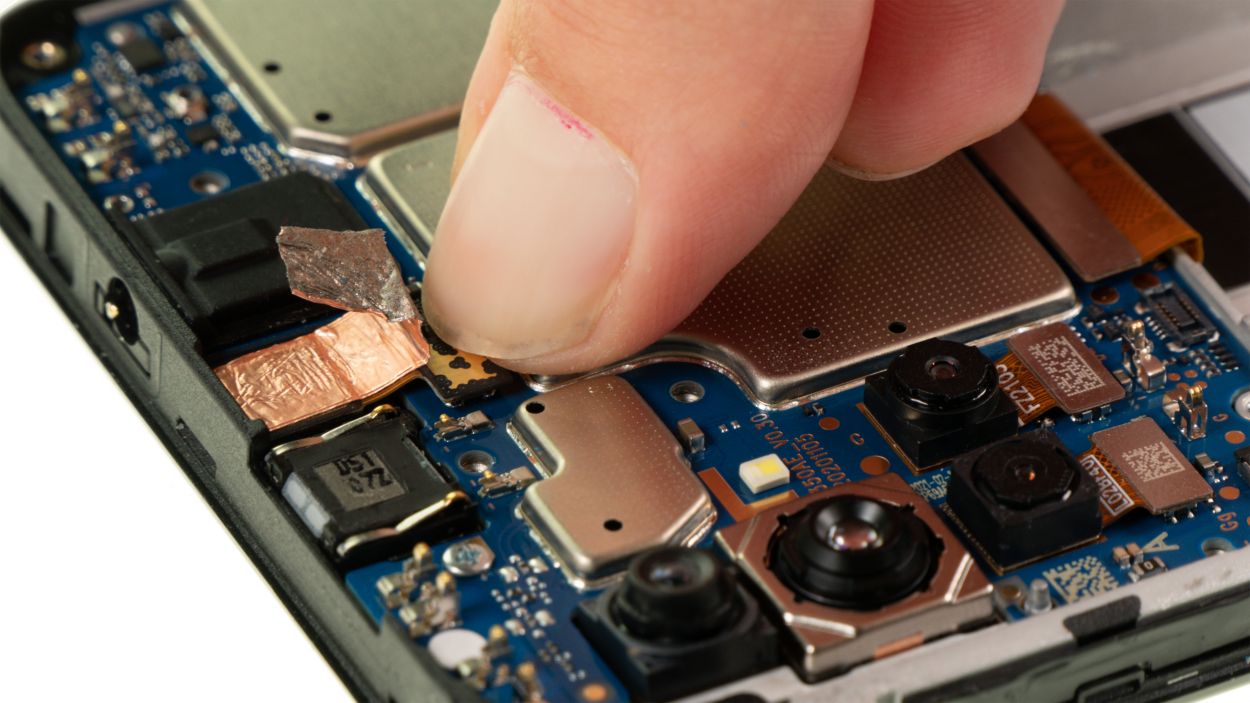
– Gently press the front camera connector into the motherboard until you hear that satisfying click. It’s like a little high-five for your device!
– Once that’s all snug and secure, cover the connector back up with the copper foil. It’s like tucking your gadget into bed!
Step 45
Typically, the leftover adhesive on the back of the battery is just enough to stick it back on securely. If you find yourself in a sticky situation, our universal adhesive+strips+Moto+G10&crid=1TJIMMAJSUJUZ&sprefix=repair+tools%2Caps%2C165&linkCode=ll2&tag=salvationrepa-20&linkId=c486487cf454ce8edd6f5beefab4110f&language=en_US&ref_=as_li_ss_tl’>adhesive strips are a great option to get that battery back in place!
Step 46
– Gently place the fingerprint scanner back where it belongs on the motherboard. You’ve got this!
Tools Used
Step 47
Remember, connectors are like friends—never force them together! Doing so could cause some serious damage and ruin the whole component. Keep it gentle and give them the love they deserve!
– Pop that fingerprint scanner back into action by gently pressing its connector onto the motherboard. You should hear a satisfying click as it settles in place.
Step 48
Remember to connect the battery connector last! It’s a great way to dodge any unexpected short circuits. Keep it safe and smooth!
– Gently plug the battery connector back into the motherboard, making sure it fits snugly like a puzzle piece!
Step 49
Just a friendly reminder: the fingerprint scanner needs to hang out on the plastic cover. So, make sure to keep it to the side while you’re sliding that cover into place!
– Gently set the fingerprint scanner aside for now.
– Carefully position the plastic cover over the motherboard and give it a nice, firm press.
– Now, let’s place the fingerprint scanner right on top of that cover.
Tools Used
Step 50
2 × 3.3 mm Phillips
7 × 3.9 mm Phillips
Hey there! Just a friendly reminder to keep those screws sorted – mixing up the lengths could lead to a screen disaster! Let’s keep everything in its right place and avoid any mishaps. If you need help, you can always schedule a repair.
– Secure the plastic cover in place by tightening the nine Phillips screws. Let’s get that back on nice and snug!
Tools Used
Step 51
If things aren’t quite right during your testing phase, go ahead and power down your device. Then, take a moment to check that everything is snug and secure. You’ve got this!
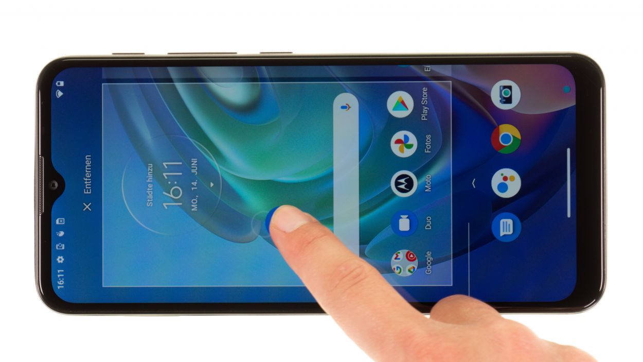
– Fire up your Moto G10 and get ready to roll!
– Give your screen a little test drive by dragging an app around to see if the touch is working like a charm everywhere.
– Take a moment to check for any pixel hiccups and make sure the colors are looking just right.
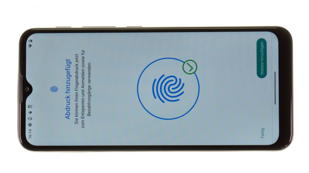
– Next up, let’s see how that fingerprint scanner is holding up!
– For testing out the other components, feel free to use our handy checklist as your trusty guide.
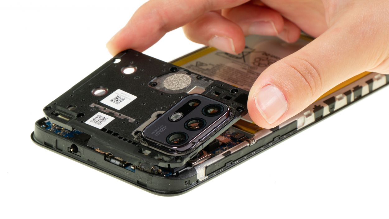
Step 52
Make sure the back cover sits nice and flat all around. If it’s sticking up in one spot, that usually means there’s a sneaky component inside that hasn’t been put in just right. Let’s get it sorted!
– Once everything is functioning smoothly, gently press the back cover onto the screen unit. You’ll hear a satisfying click as it locks into place!
– Use your hot air tool to warm up the area around the camera module and fingerprint scanner. This will help the glue stick like a champ!
Tools Used
- heat gun to heat parts that are glued on so they’re easier to remove.
In most cases, you can also use a hairdryer.” rel=”noopener”>Heat gun
Step 53
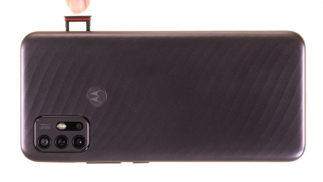
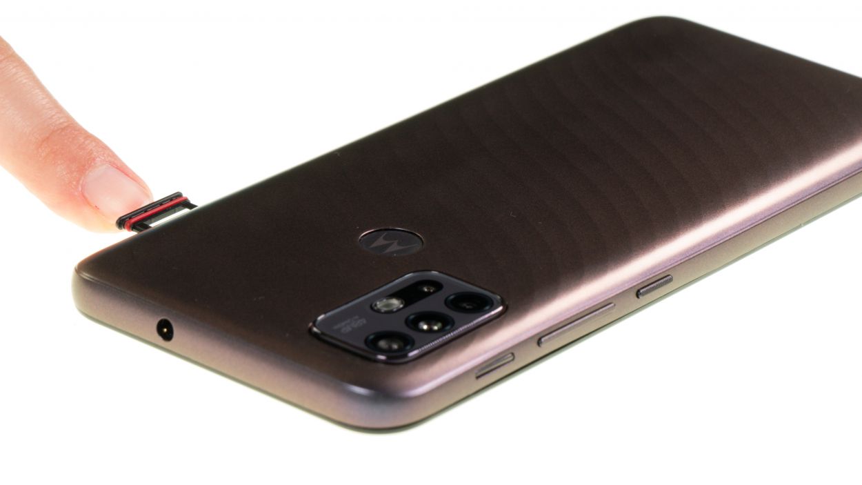
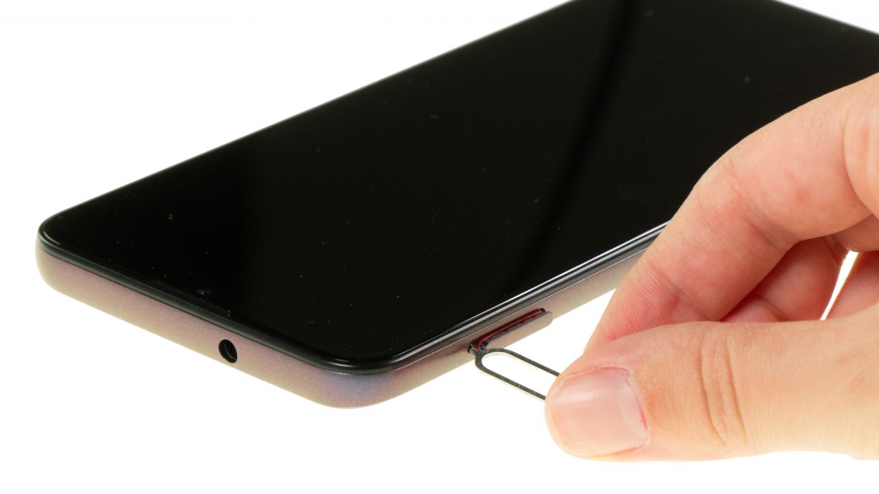
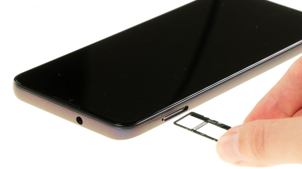
Remember to pop that SIM tray in the right way! If you give it a little too much oomph while pushing it the wrong direction, you might end up doing a number on both the tray and your beloved moto g10. Take it easy and keep it safe!
– Wrap up your repair by sliding the SIM tray back in. You’ll know it’s snug when you hear a satisfying little click!