DIY Guide to Replace Samsung Galaxy Note Edge Screen
Duration: 60 min.
Steps: 26 Steps
In this repair guide, we’re diving into the world of fixing that pesky display on your Samsung Galaxy Note Edge. If you’re dealing with cracked glass, a touchscreen that’s throwing a tantrum, or an LCD that’s gone dark or is flickering, you’ve come to the right spot! Get ready to take matters into your own hands and bring your device back to life. And remember, if you need help, you can always schedule a repair.
Step 1

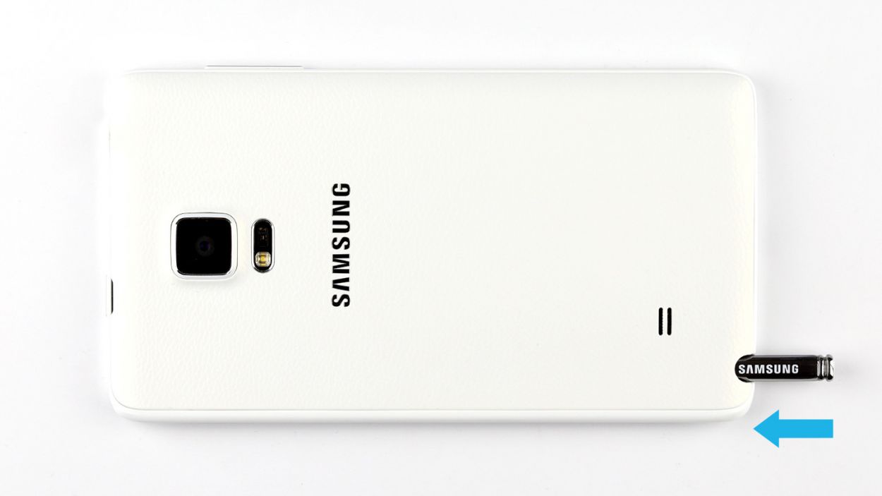
– Use your finger to pull the stylus out of your Galaxy Note Edge.
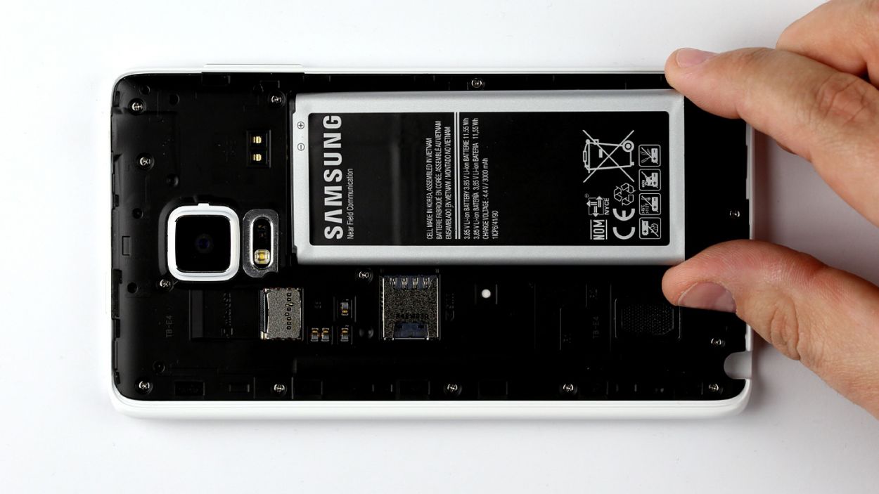
Step 2
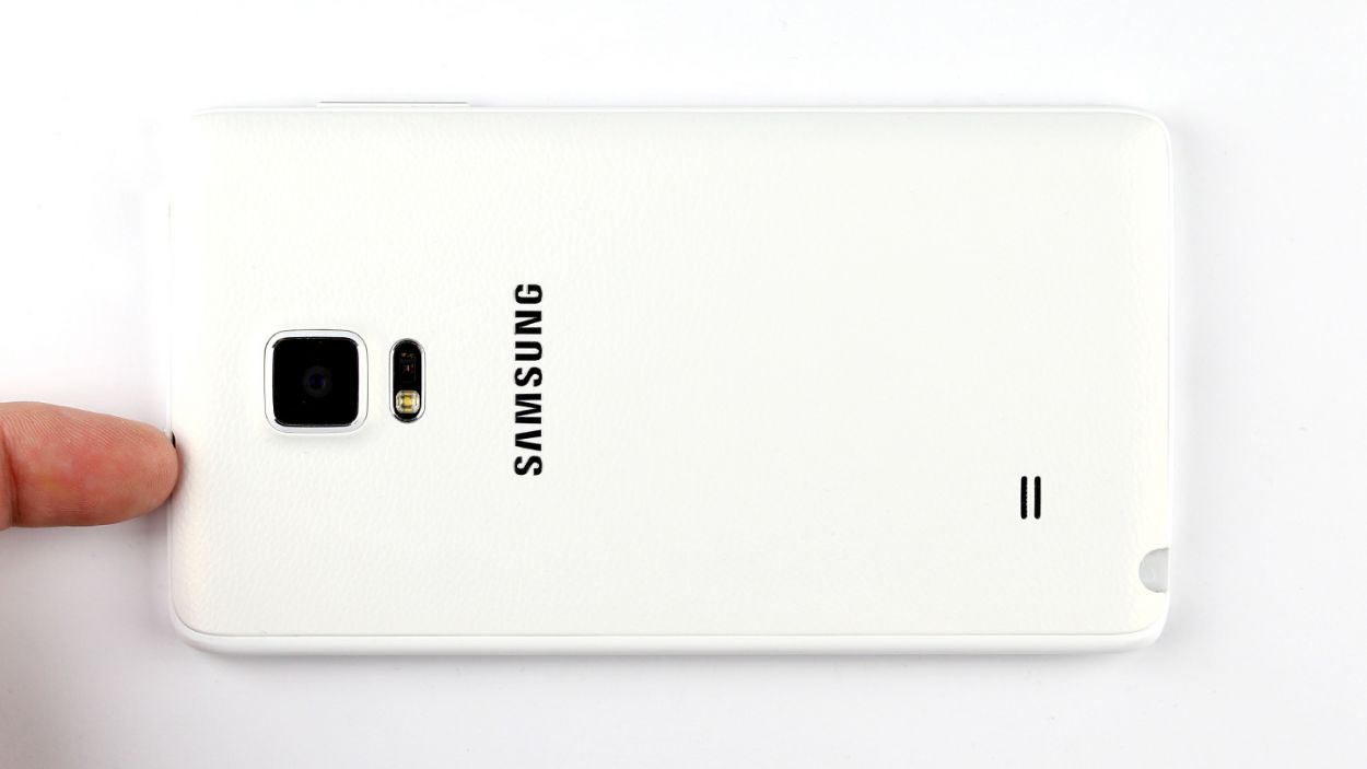
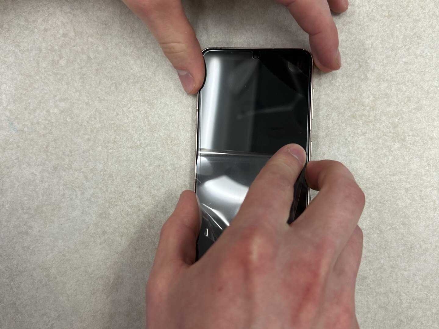
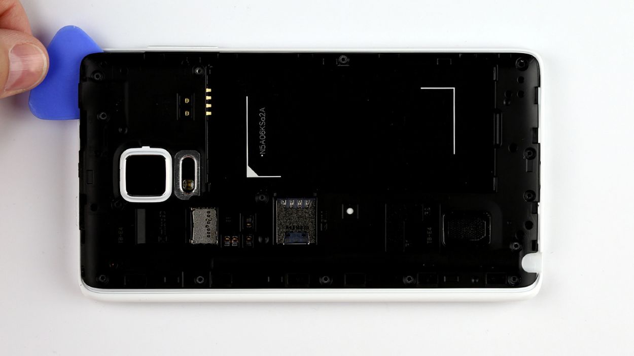
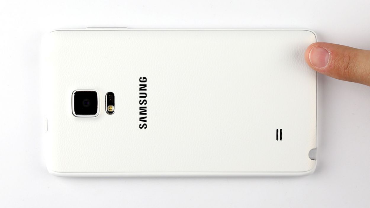
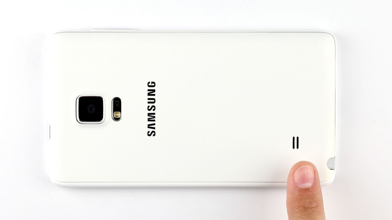
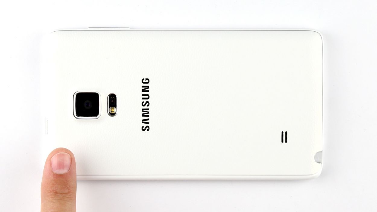
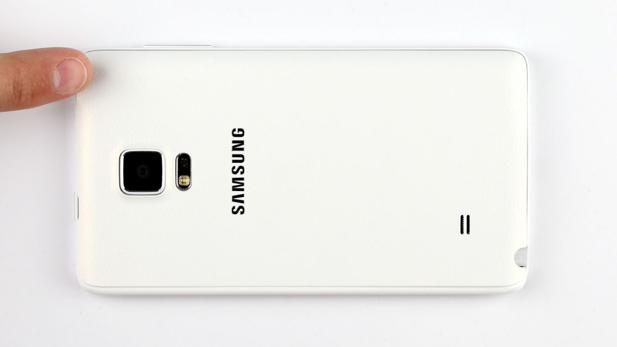
– First things first, let’s get that back cover off your device! Look for a little groove at the top of your Galaxy Note Edge where you can gently insert your fingernail. Remember, the back cover is held on at a few points, so feel free to use your fingers in a few spots and give it a gentle tug. You’ve got this!
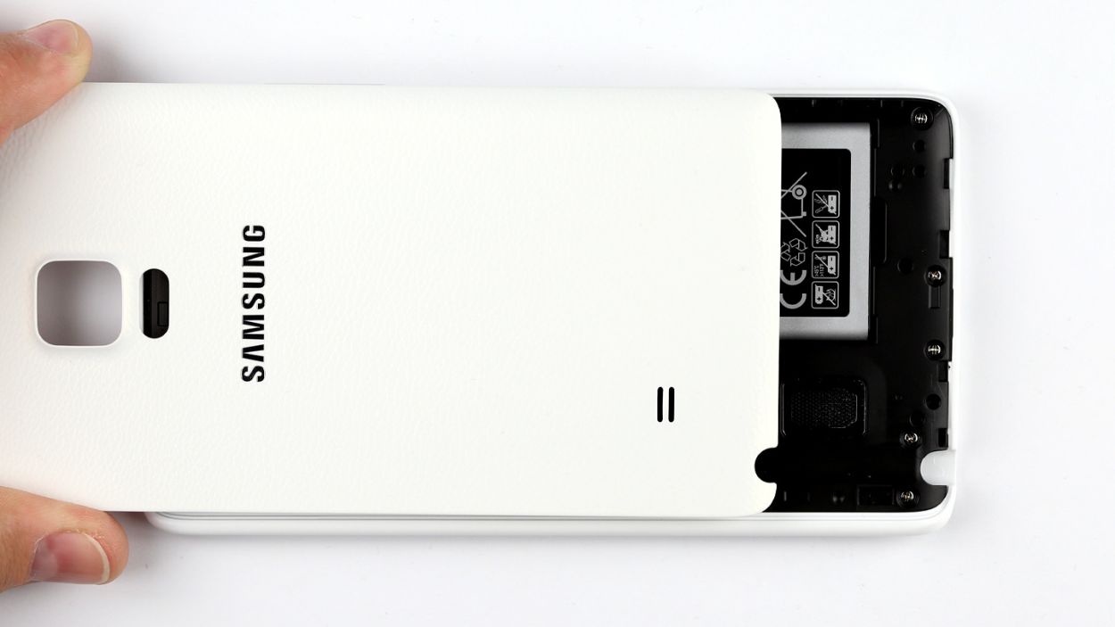
– Now, go ahead and remove the back cover.
Step 4

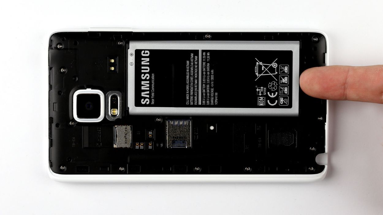
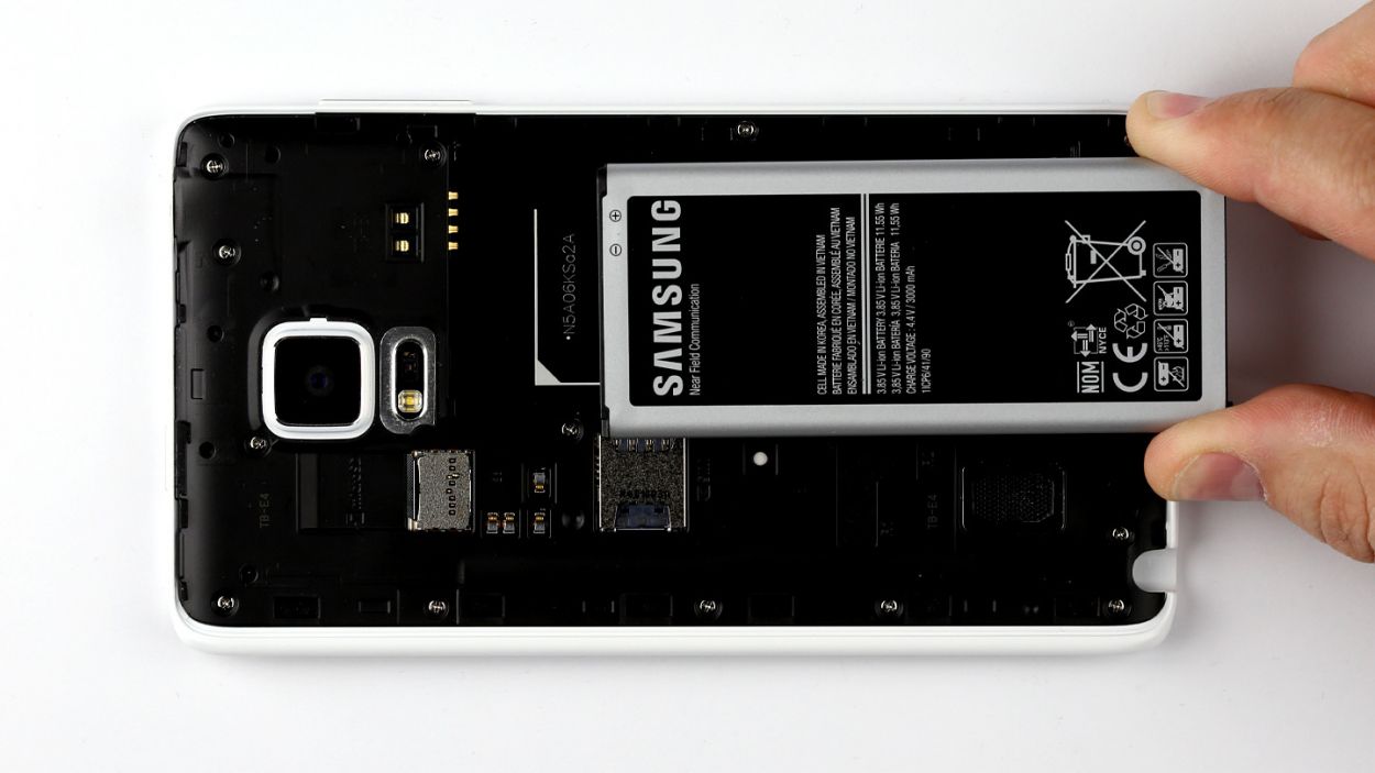
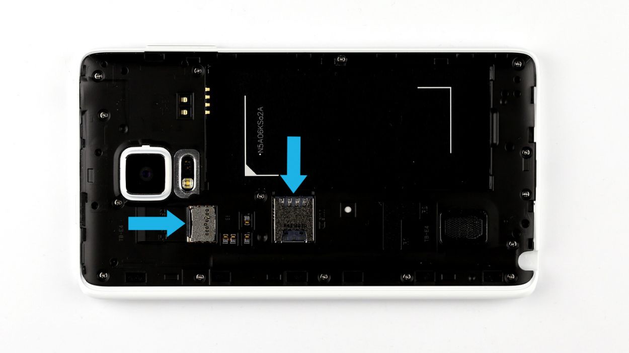
– Give that SIM card a little nudge with your finger and pop it right out of the slot!
– Next up, gently take out the microSD card from its cozy little home in the slot.
Step 5
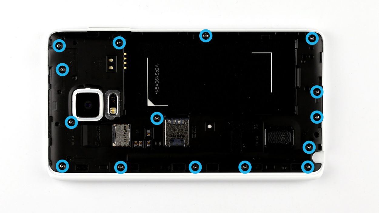


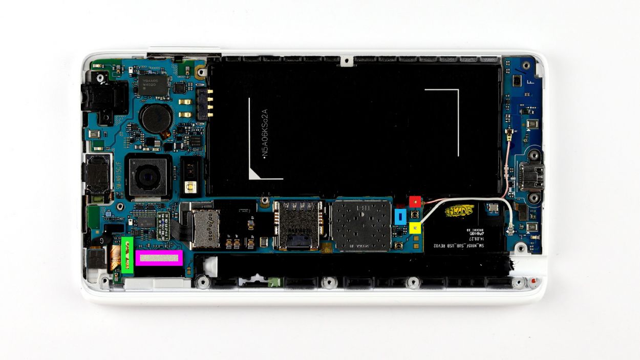
– Time to get those screws out! Grab your trusty screwdriver and unscrew the fifteen screws that are keeping the chassis snug as a bug. We’re talking about 15 x 4.0 mm Phillips screws here.
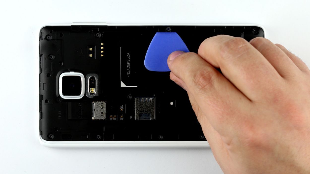
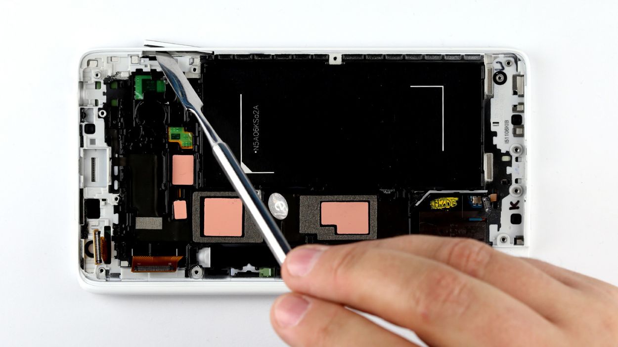
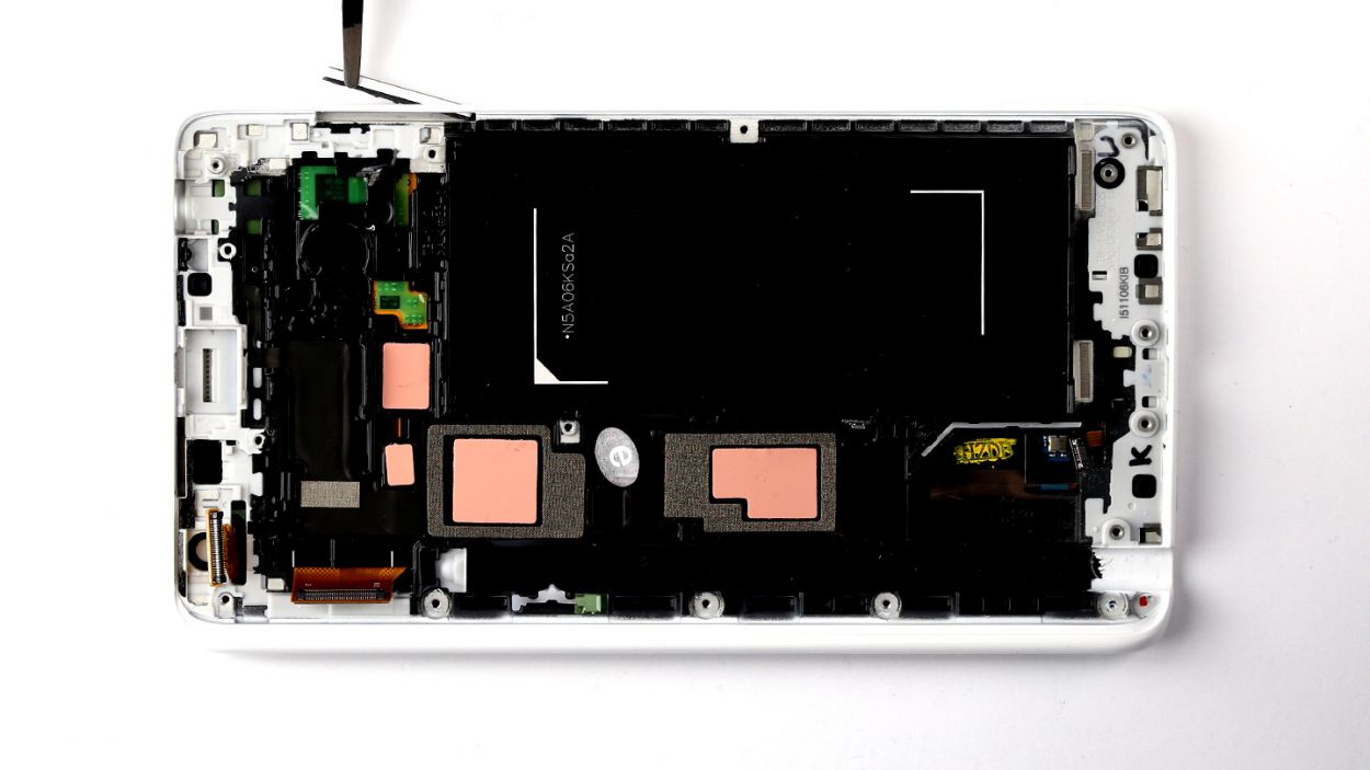
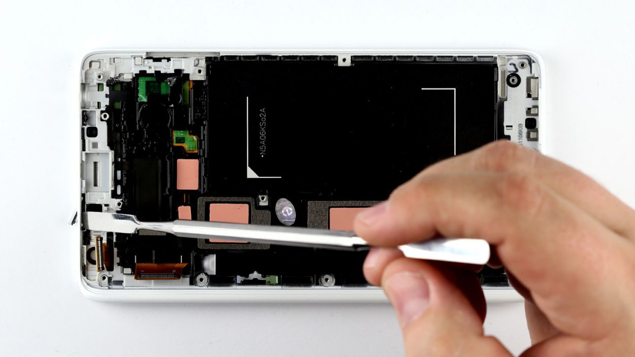
– Now, the chassis is playing hard to get with the display frame. No worries! Just slide your pick in between the chassis and the display frame, and gently unhook those pesky hooks. Start at the battery recess for an easier time.
– Keep that pick moving around the device like a pro, and disconnect the frame from the chassis completely. You’ve got this!
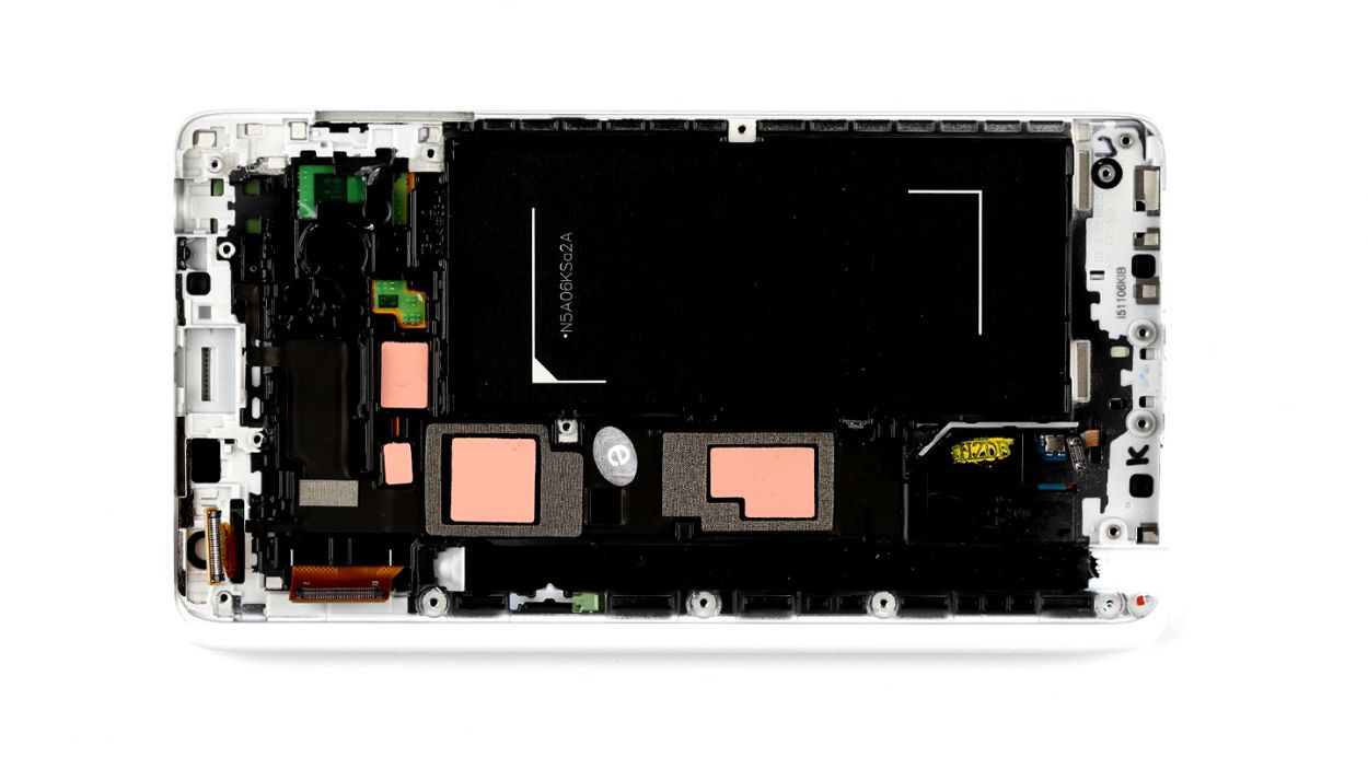
– Finally, lift that chassis up and away. You’re making great progress!
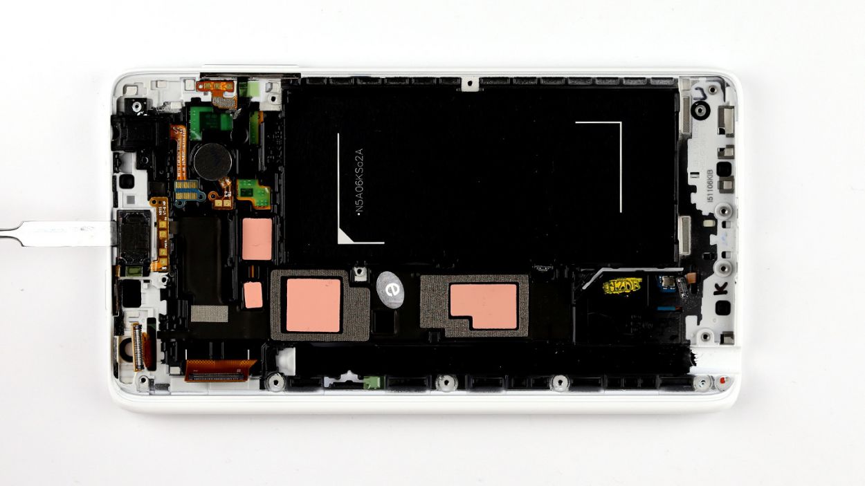
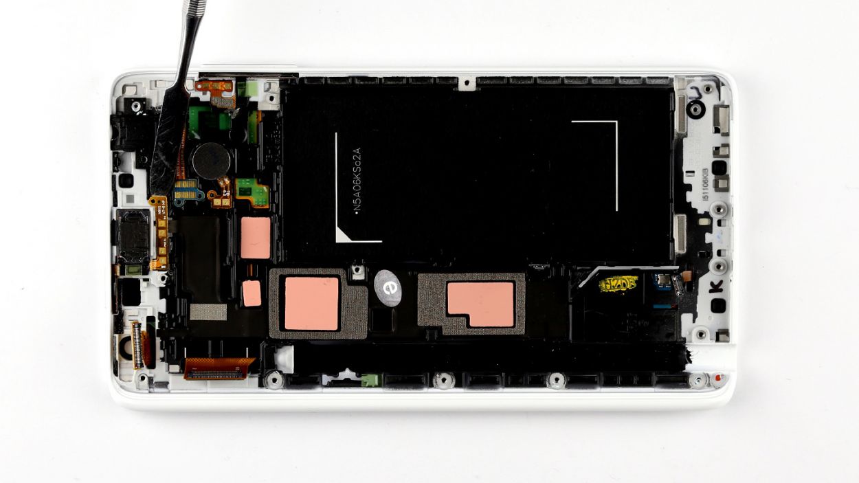
Step 6
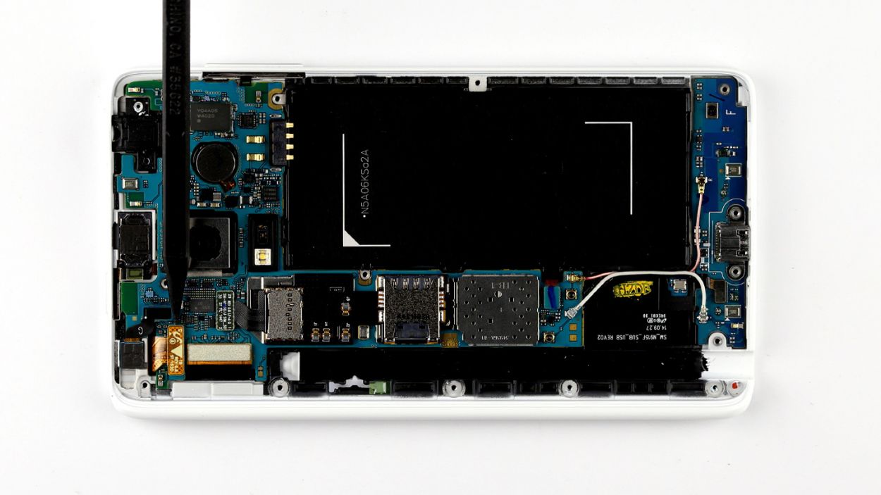
– Time to get your hands a little dirty! Start by disconnecting all the connections to the logic board in the order below: Touchscreen, LCD, Home button/fingerprint sensor, Wi-Fi antenna cable, and Bluetooth antenna cable.
– Now, grab that spudger and let’s get to work! Use the pointed tip to gently disconnect the plug contacts. Slide the spudger underneath the connector and apply just a bit of force to pry it off the logic board. You’ve got this!
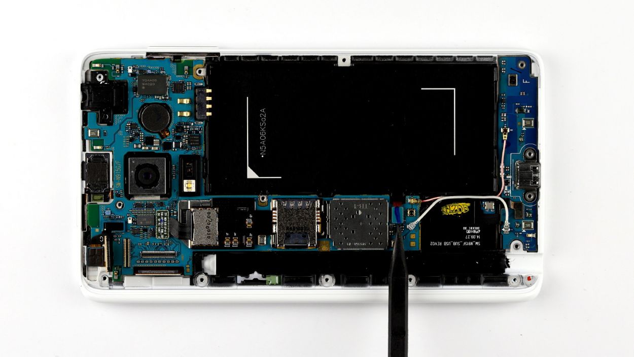
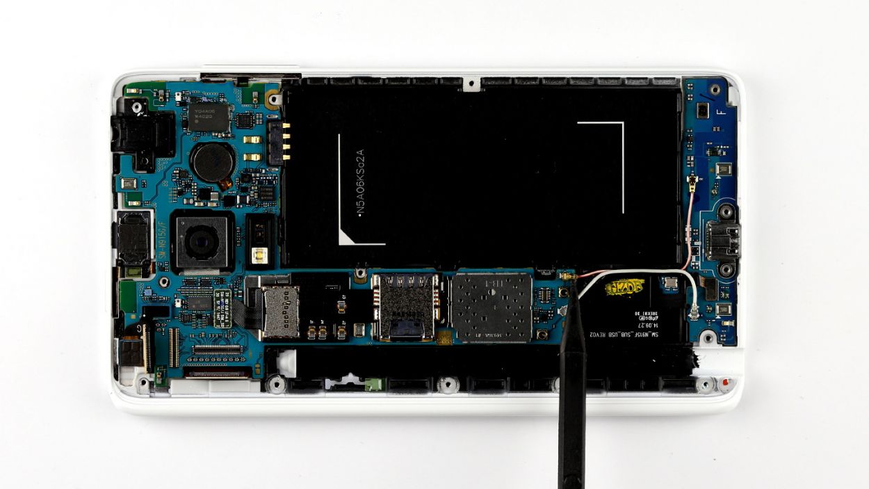
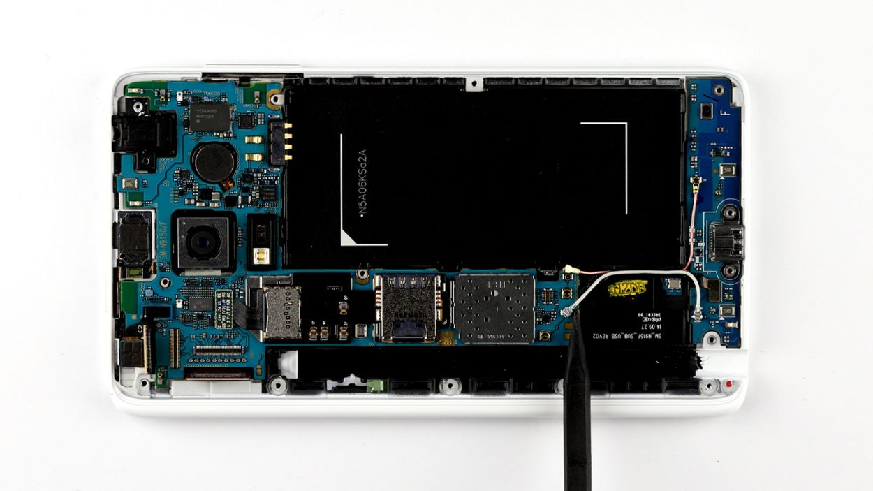
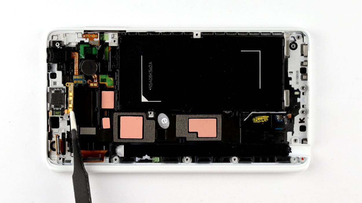
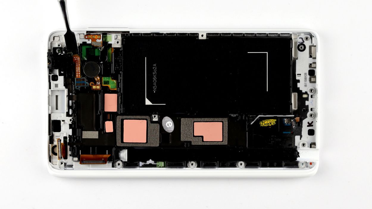
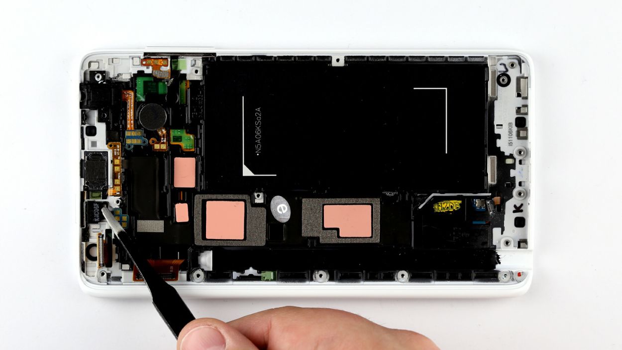
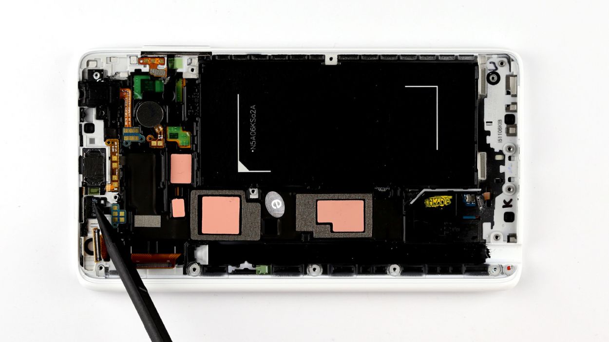
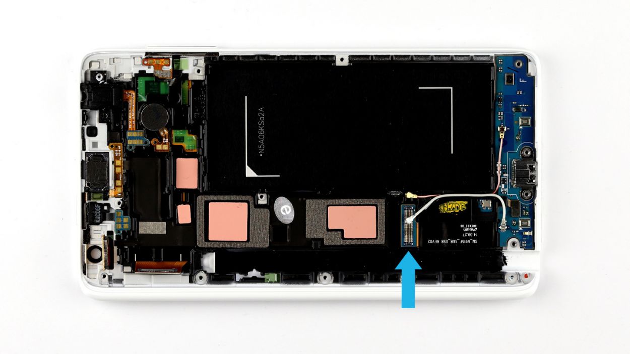
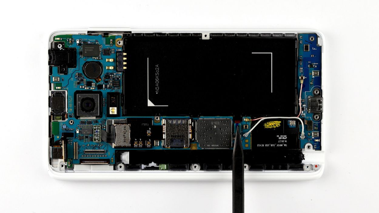
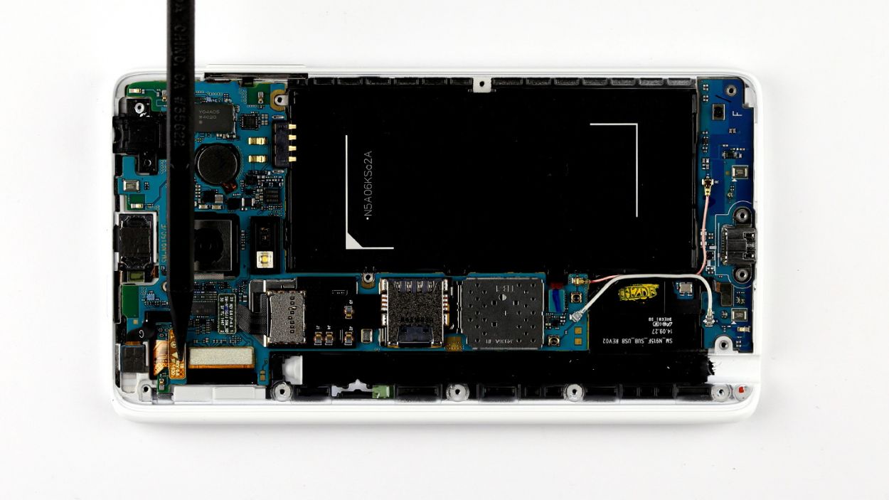
Step 7
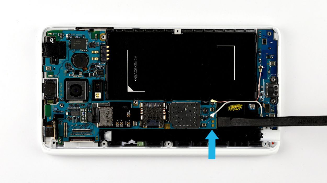
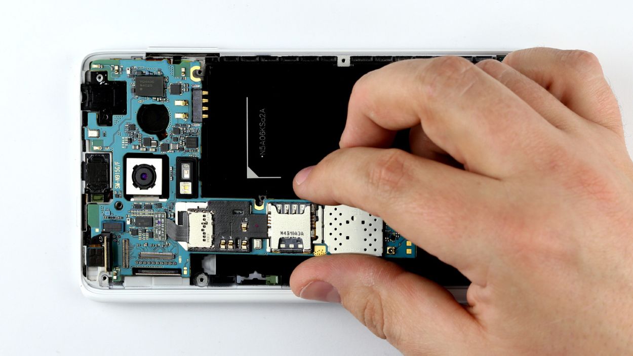

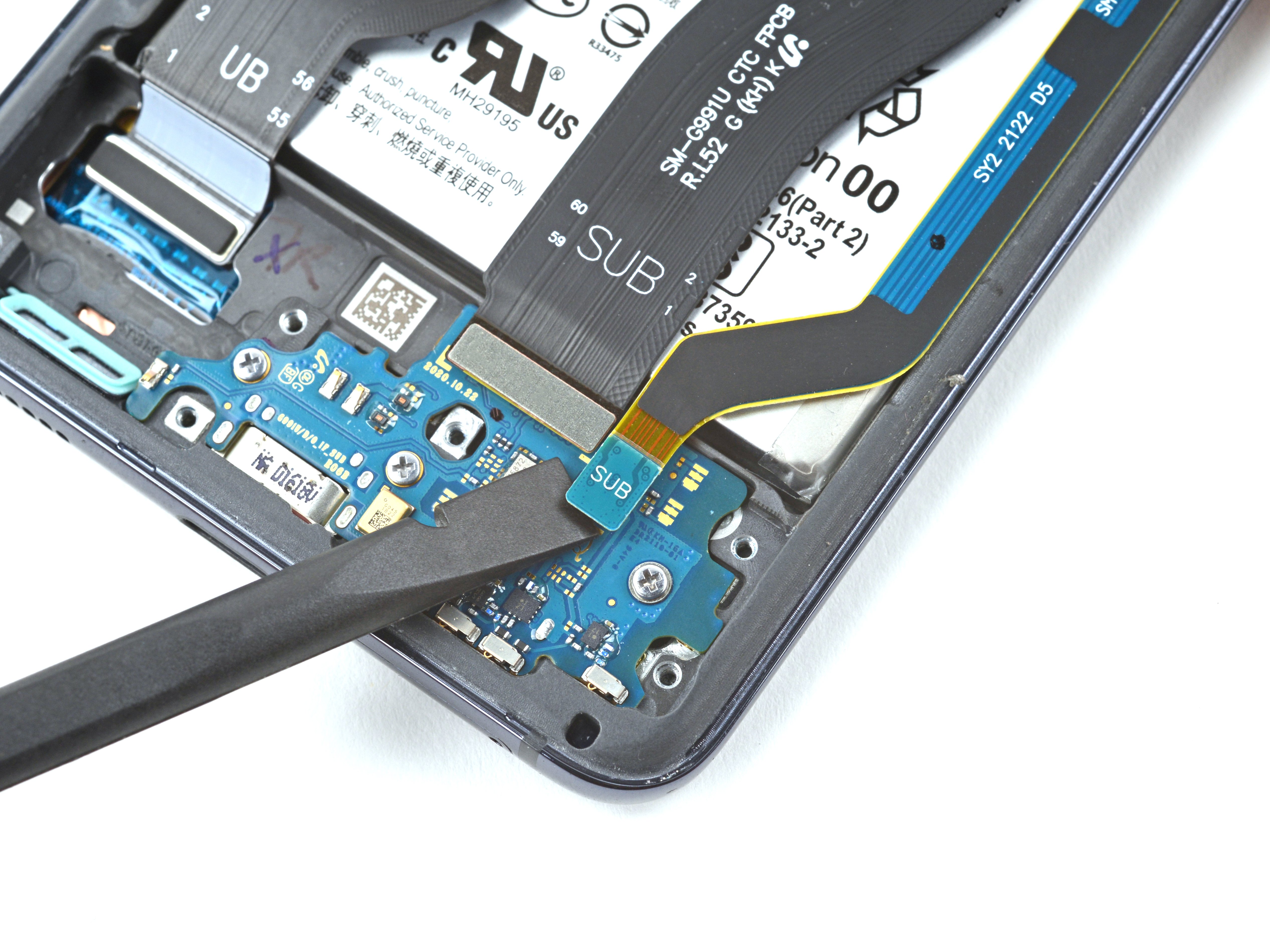
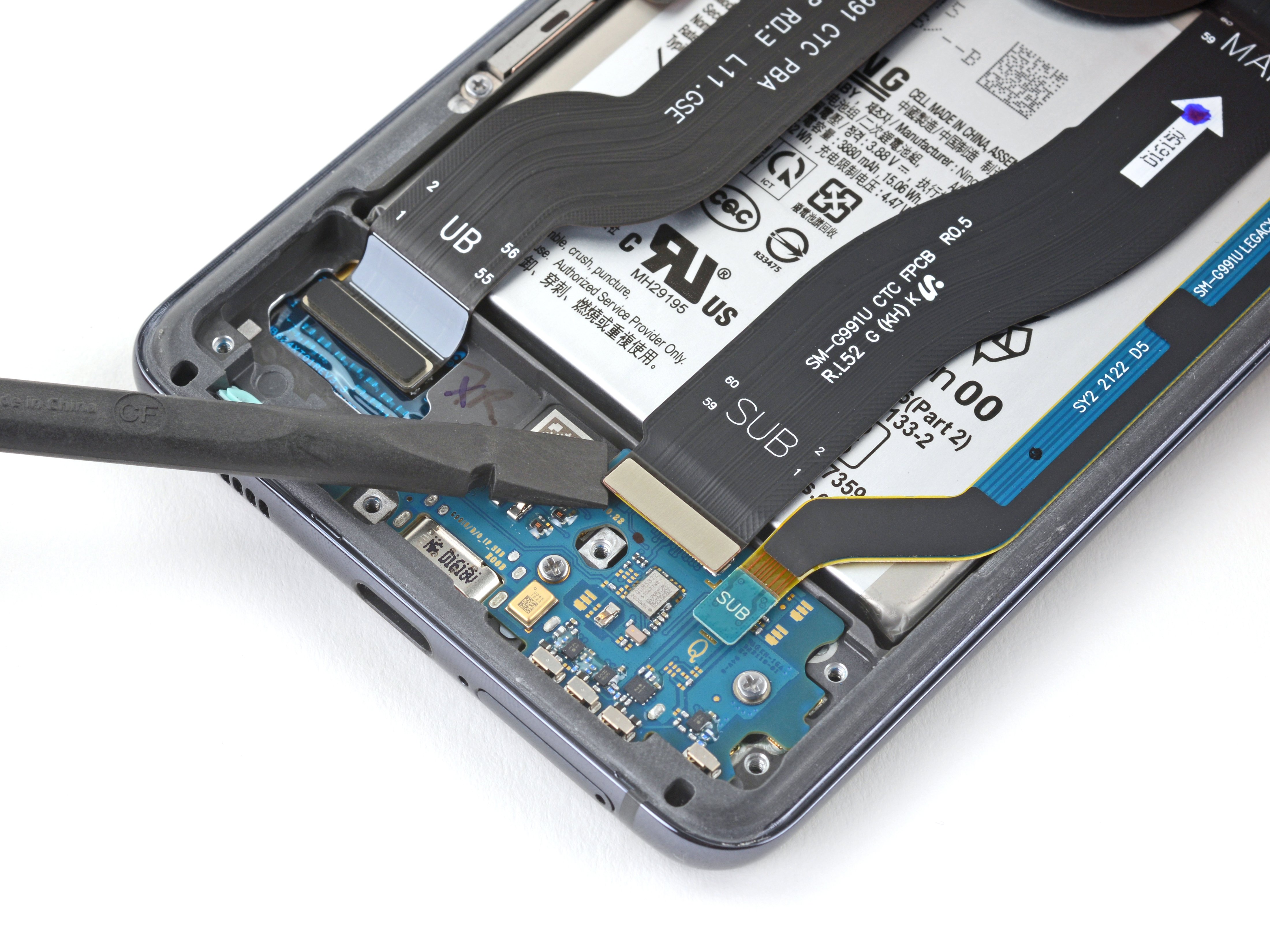
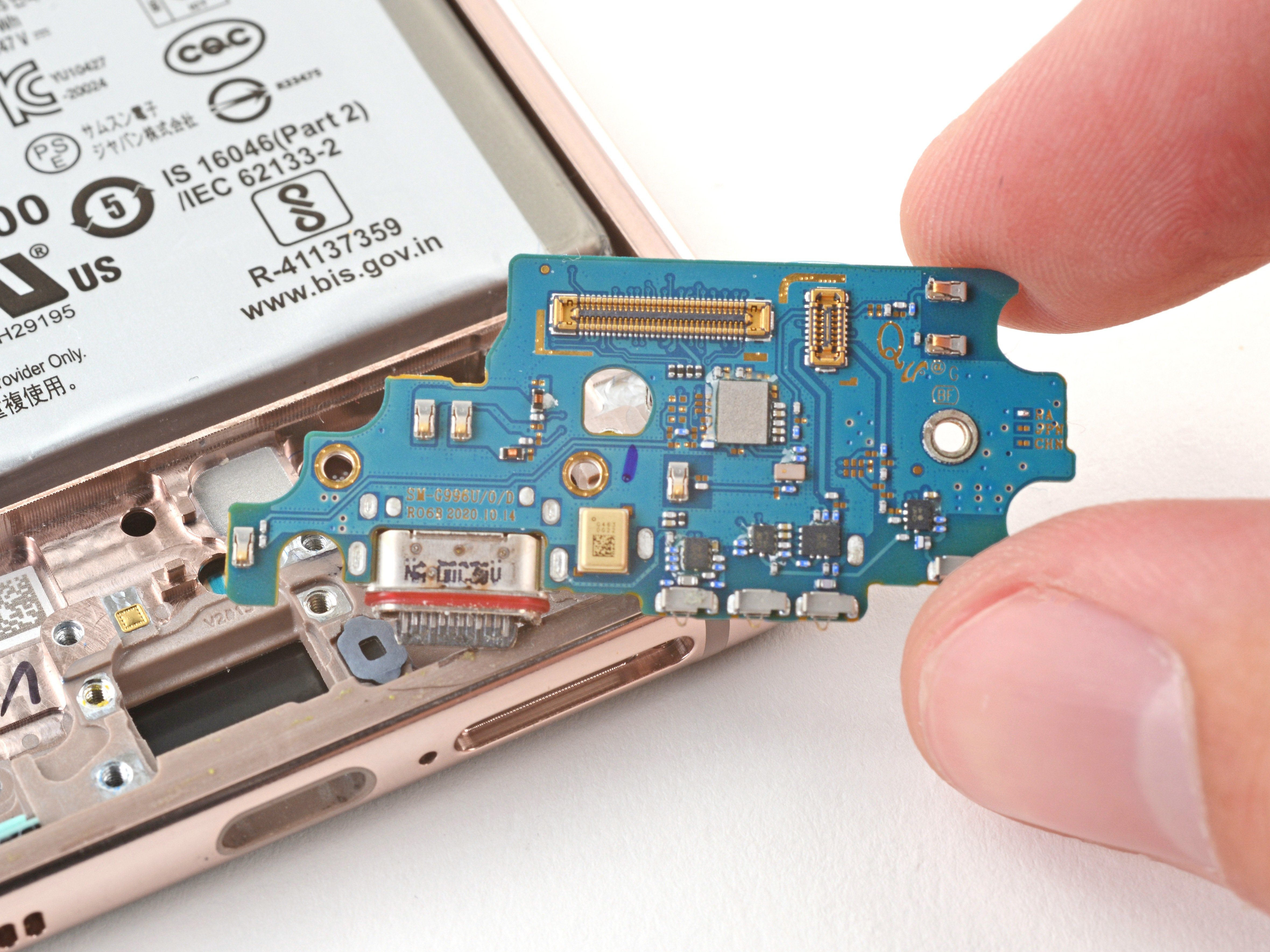
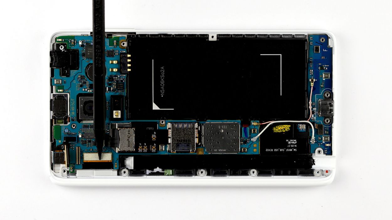
– Alright, let’s get that logic board disconnected! The bottom of the logic board is linked to the sub-board with a connector (look for that blue arrow!). Before we can lift out the logic board, we need to break that connection. Grab your trusty spudger and gently slide the flat end between the logic board and the enclosure. Make sure to target the sub-board’s flexible flat cable. Just a gentle nudge will do—no need to go all Hulk on it, as we don’t want to damage that cable!
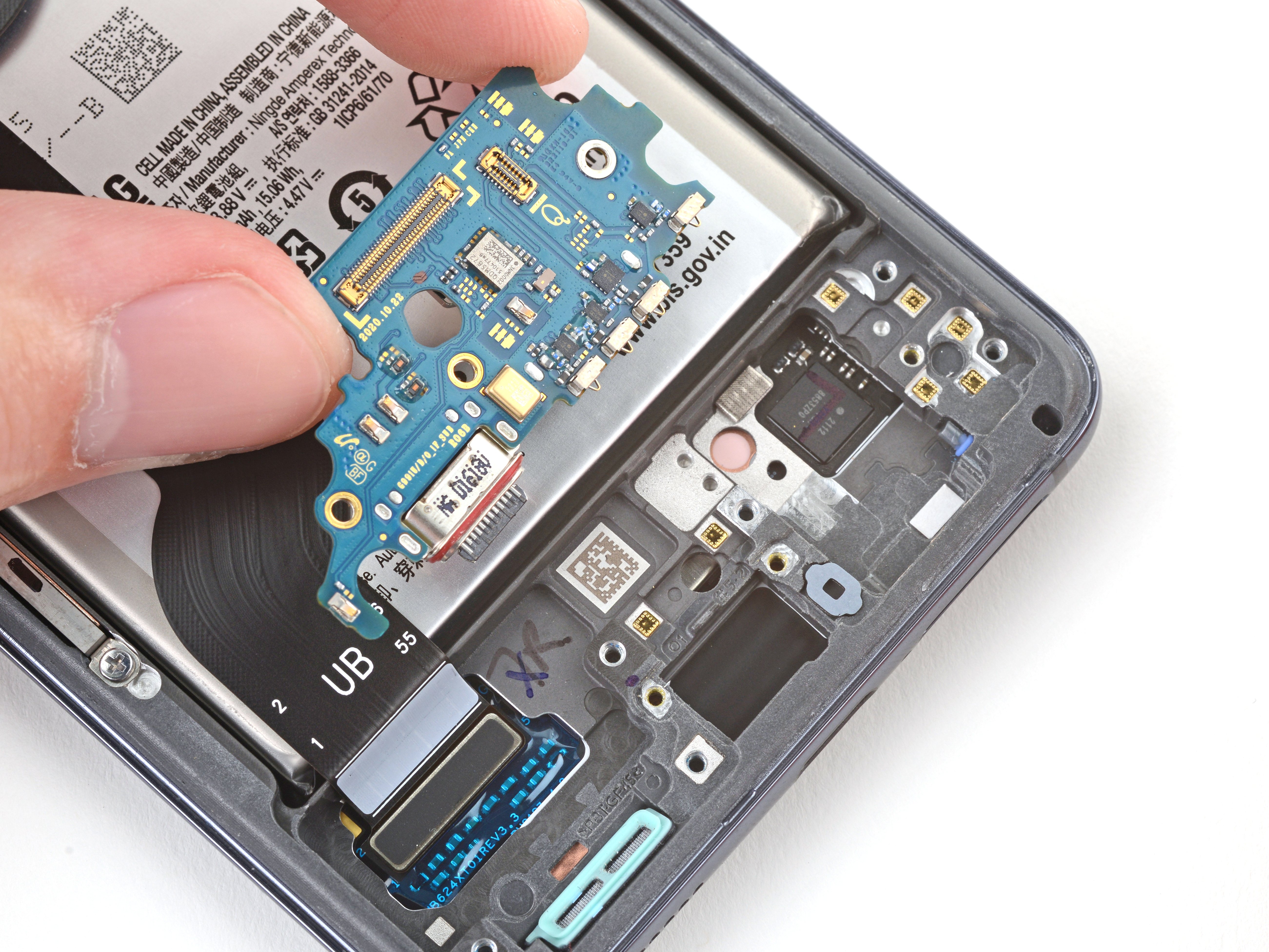
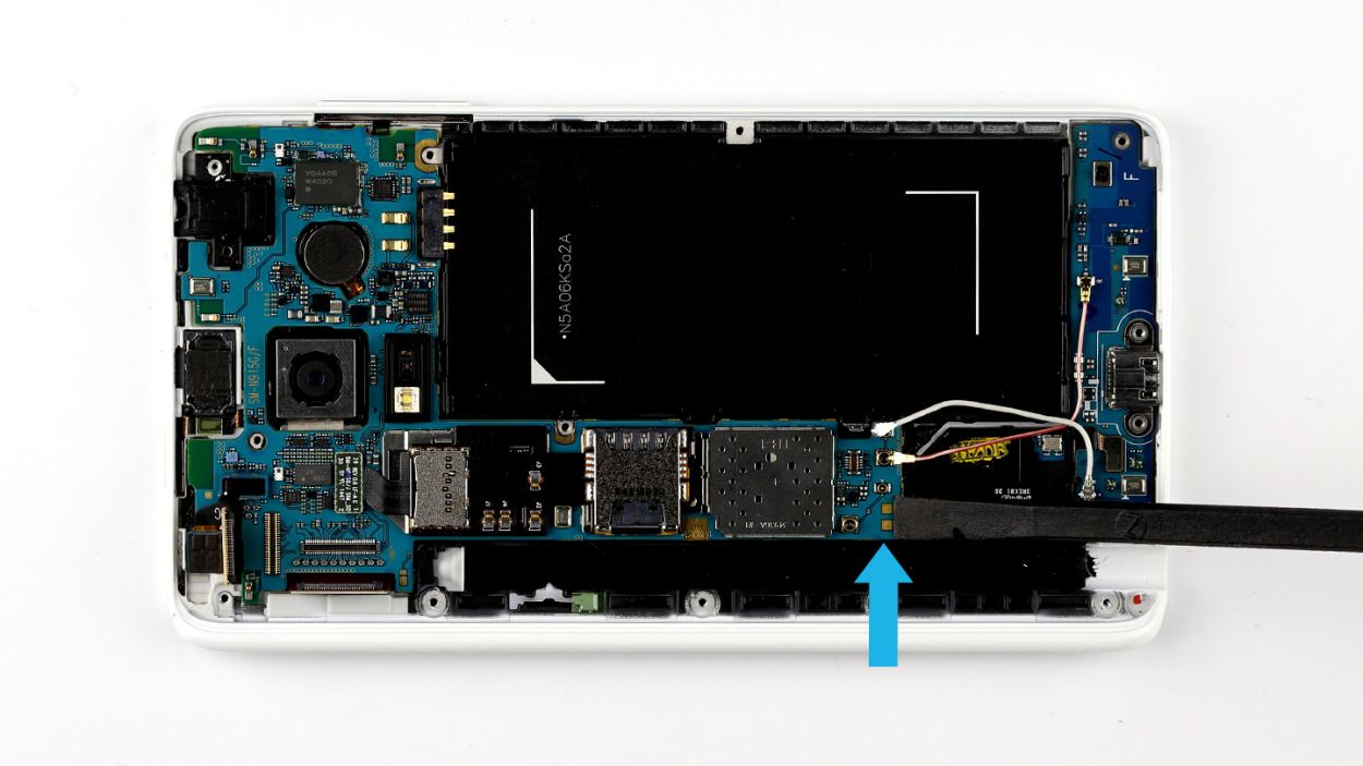
– Now, it’s time to lift out the logic board! Use your fingers to carefully pull it out of the enclosure. Give it a little tilt at the thin end to make lifting easier. You’ve got this!
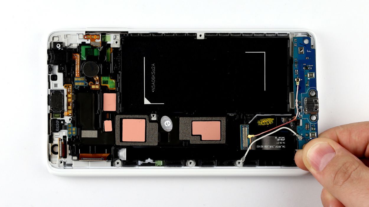
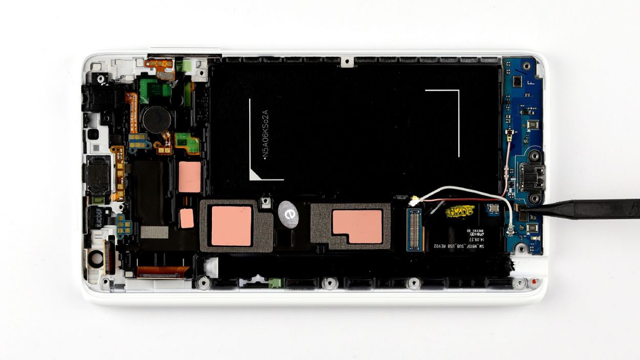
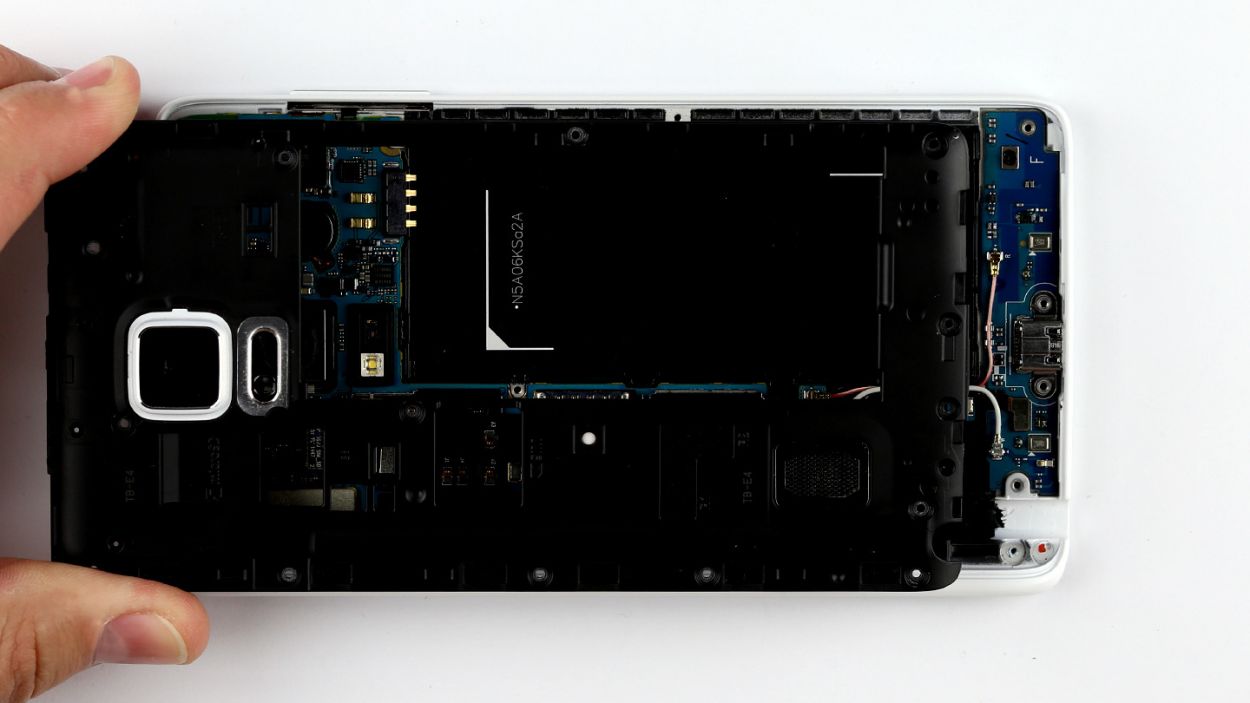
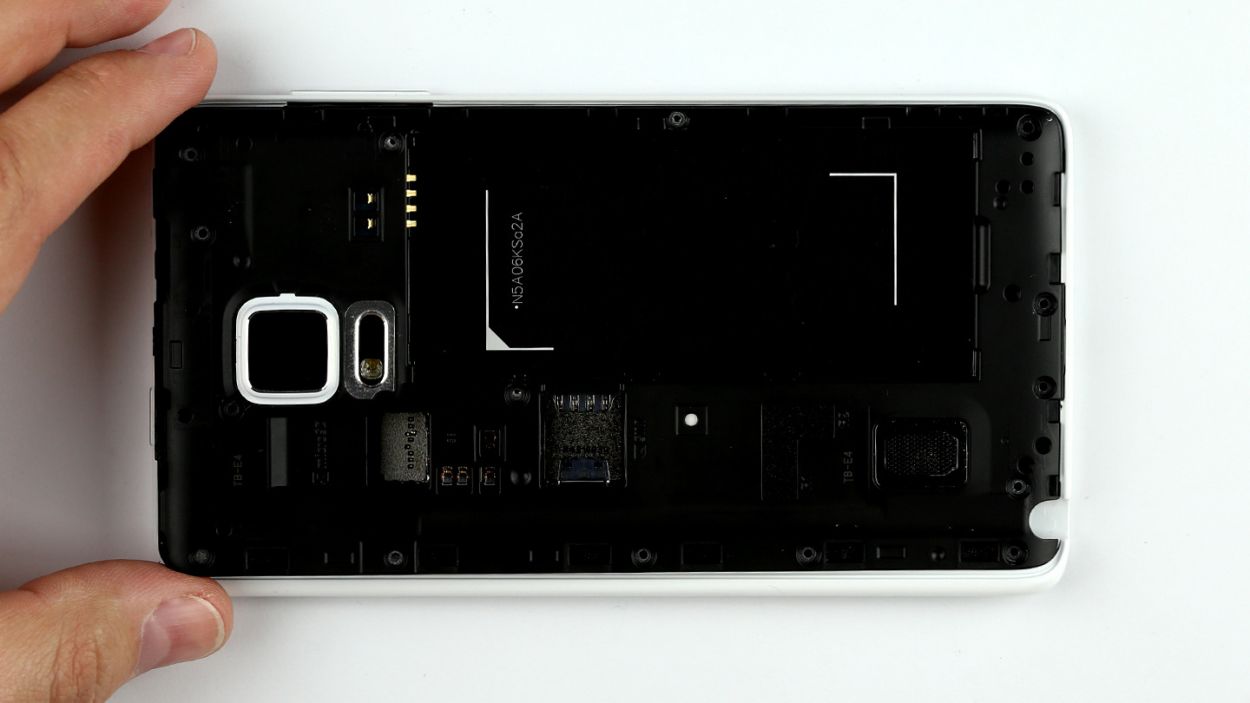
Step 8
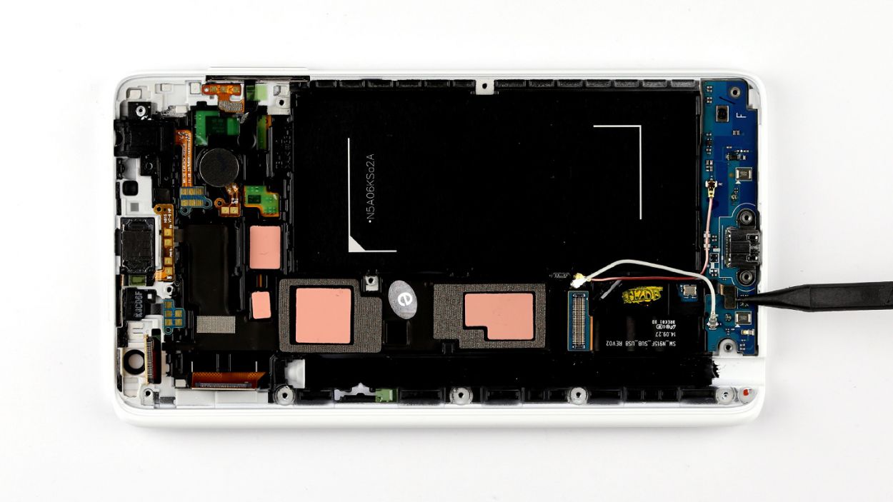
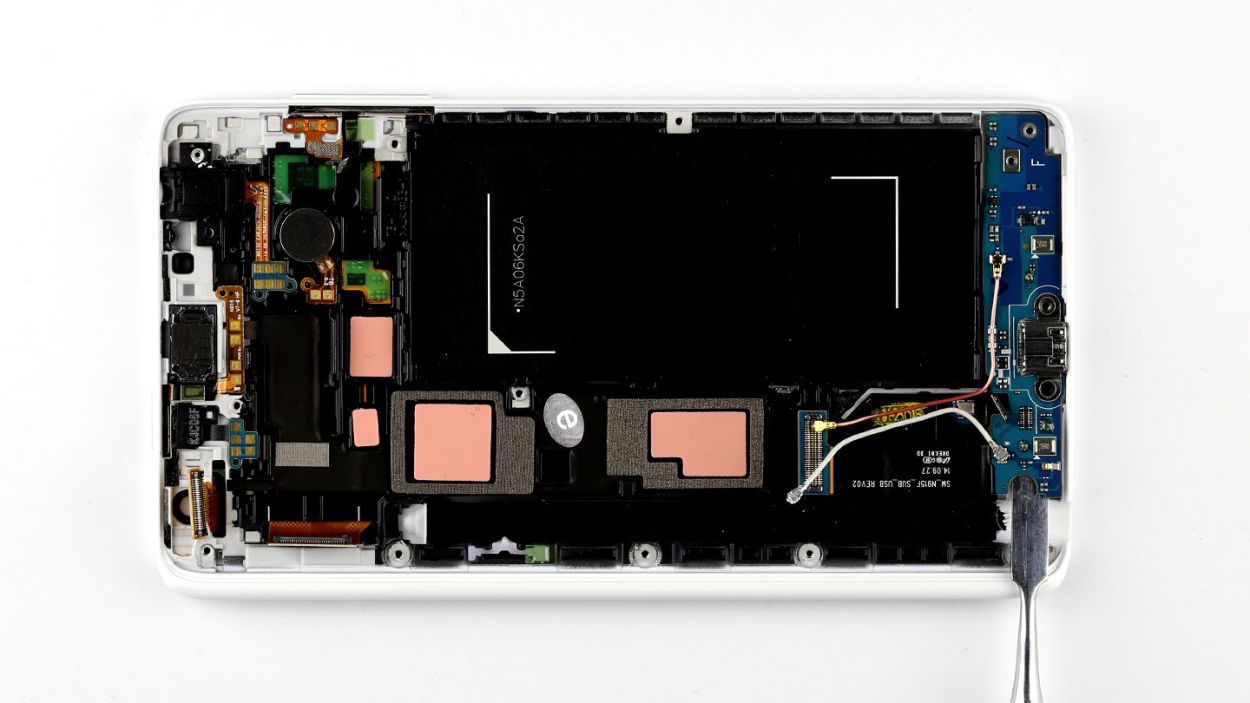

– Gently unplug the sensor buttons from the sub-board using a spudger to avoid any mishaps.
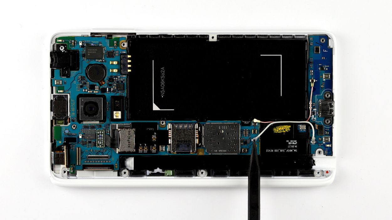
– The sub-board is stuck to the display frame with some glue love. Carefully slide a steel laboratory spatula between the two to separate them. If the glue is feeling extra clingy, a little hot air can help loosen things up.
– Once you’ve got it loosened, simply lift the sub-board out of the enclosure with your fingers.
Step 9

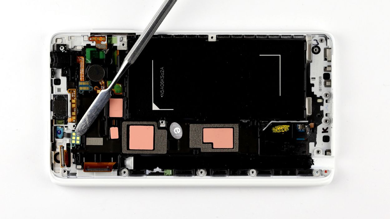

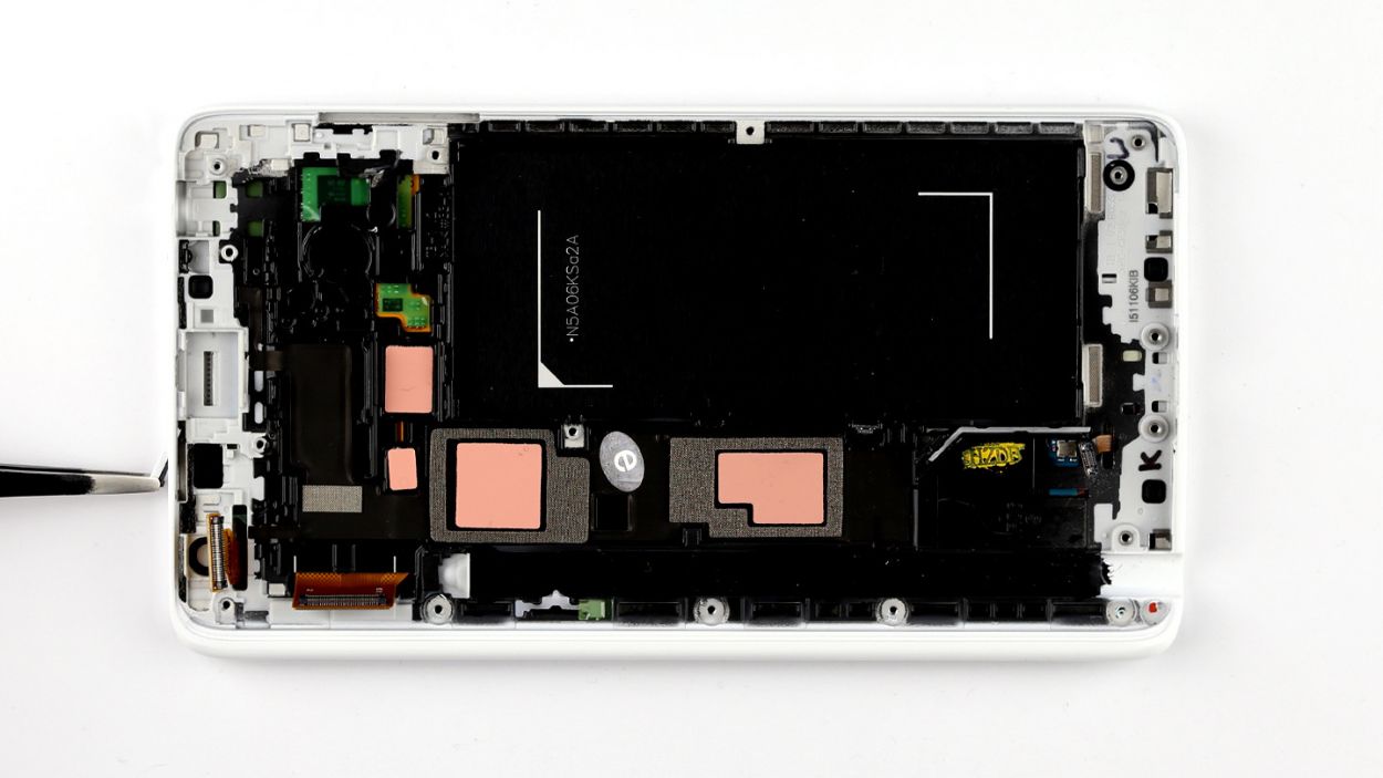
– First things first, there’s a tiny plastic cover keeping the proximity sensor snug in the display frame. Go ahead and pop that little cover off.
– Next up, the sensor’s contact is glued to the enclosure. Gently slide a steel laboratory spatula between each contact and the enclosure to free them. If the glue is being a bit stubborn, a little hot air can help loosen things up.
– Finally, carefully lift the proximity sensor out of the display frame. You’re doing great!
Step 10
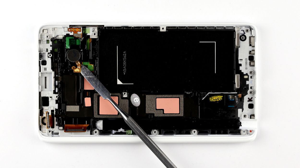
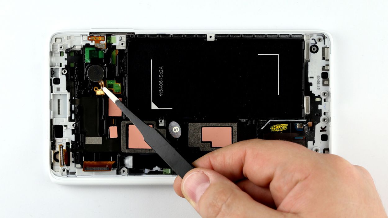
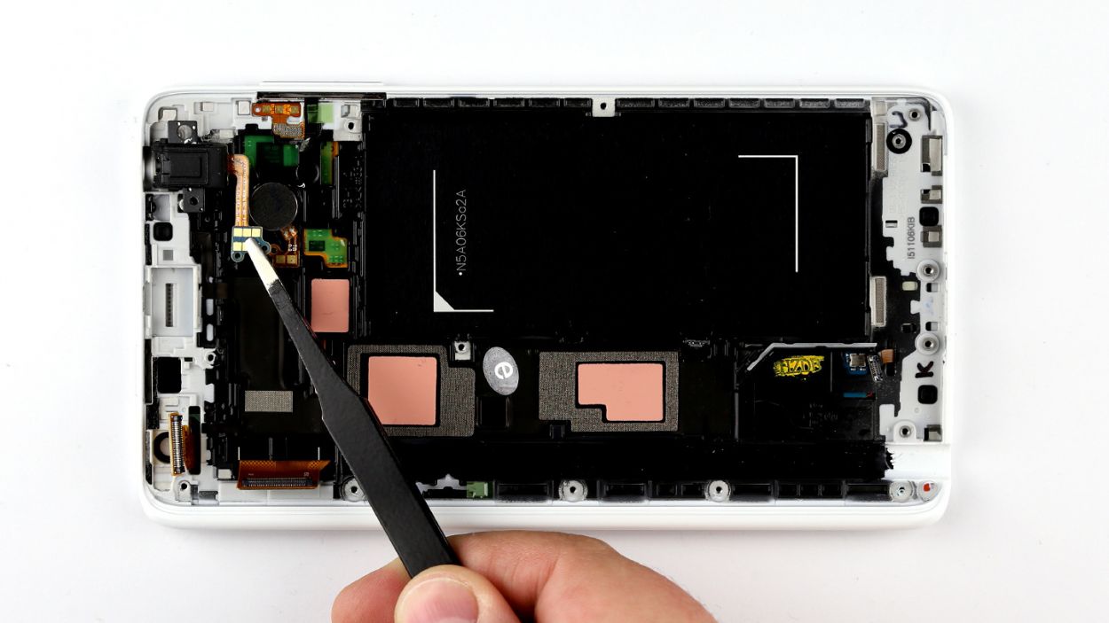
– The earpiece is nestled in a cozy little spot within the display frame. There’s a handy opening at the top where you can gently slide in your steel spatula to pop out the earpiece. Just a heads up, it’s got a light adhesive holding it in place.
– The earpiece’s contacts are also sticking to the enclosure. Give them a little nudge to break them free. Slide that steel spatula between the contacts and the enclosure to help them along.
– Now, go ahead and lift the earpiece out of the enclosure.
Step 11


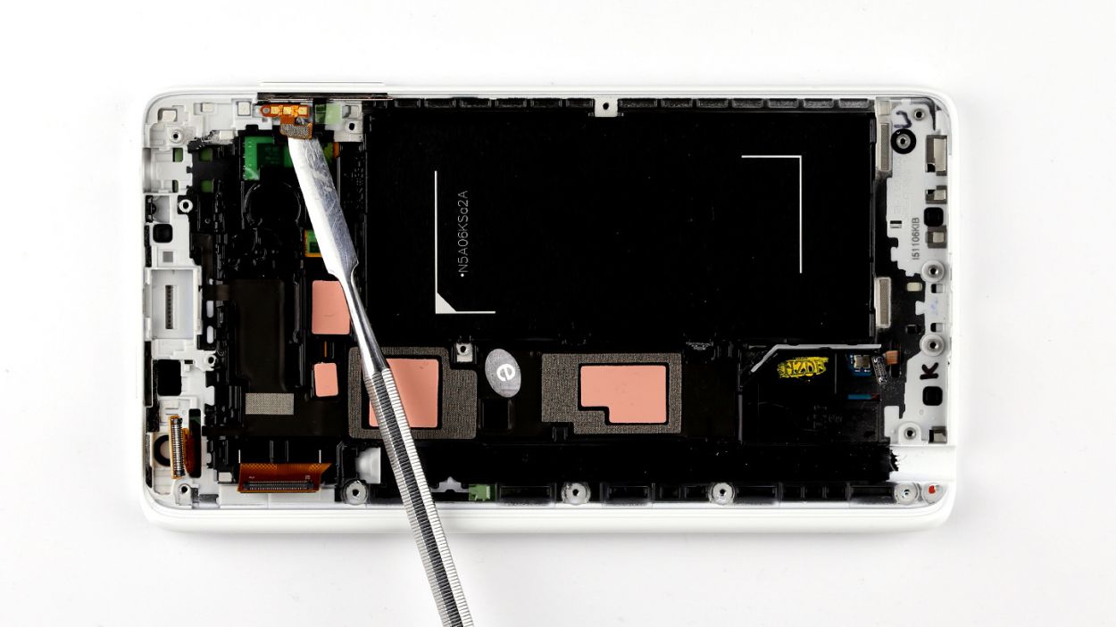
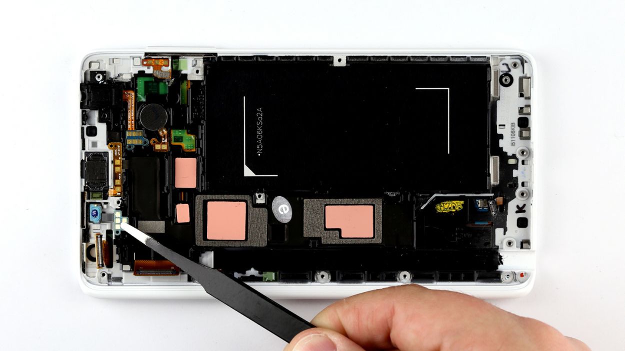
– Let’s pop that 3.5mm headphone jack out! Gently slide your steel spatula beside the jack, then wiggle it free from its little home in the display frame.
– Time for some delicate detective work! Carefully pry the socket loose, making sure to disconnect those headphone jack contacts from the frame. It’s like a tiny friendship breakup, but a necessary one.
– And there you have it – the headphone jack is free! High five! 🎉 If you need help, you can always schedule a repair
Step 12
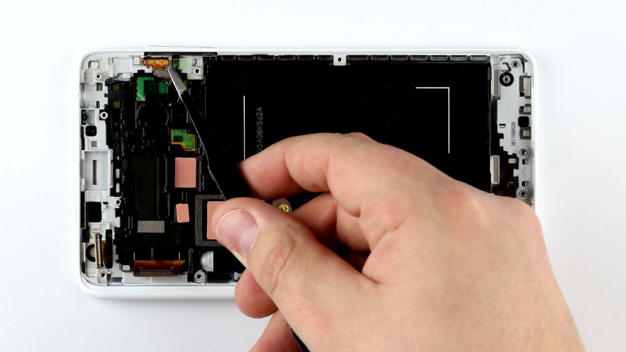
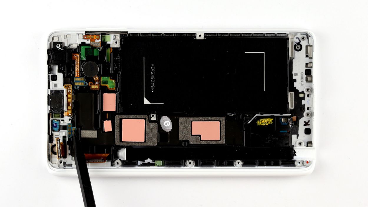
– The vibration motor is snugly attached to the display frame, so let’s gently coax it off with a steel spatula. Slide the spatula carefully between the motor and the enclosure.
– Once you’ve done that, simply lift the motor away from the display frame.
Step 13

– Grab your trusty steel spatula and gently pry off the buttons for the volume rocker switch from the enclosure. Slide that spatula between the contacts and the enclosure to break the glue’s hold!
– Next up, it’s time to liberate those buttons! Pull them up to remove them since they’re snugly fitted in there vertically.
– The plastic rocker switch is a little shy and needs a nudge to come out of the display frame. Use your steel spatula or spudger to gently push it out from the inside.
– Once it’s loose, use some tweezers to carefully pull the rocker switch out of its cozy little opening in the enclosure.
– Now, let’s tackle the standby button. It’s also a bit clamped into the display frame. Give it a gentle push from the inside to help it out.
– Finally, remove the button from the enclosure and you’re all set!
Step 14


– First things first, if your shiny new replacement part still has that protective film on its reddish thermal pads, it’s time to peel it off! Don’t forget to remove any protective film from the other adhesive surfaces too.
– Next up, let’s get that standby button back where it belongs! Slide it into the opening in the display frame – it should fit snugly in place.
– Now, let’s not forget about the volume control! Insert the plastic rocker switch for volume the same way you did before.
– Finally, pop those buttons for the volume rocker switch back in place. Insert them from above so they sit vertically in the enclosure. Give them a gentle press with your finger to ensure the glue sticks like it should.
Step 15

– Put the vibrator motor in the original position in the display frame. Make sure the motor’s contacts are in the right position. There’s an eyelet next to the two gold contacts that you have to pull over a plastic pin. Press the motor and its contacts onto the enclosure a little so the glue will stick.
Step 16
– Carefully slide the 3.5 mm jack socket back into its cozy spot in the enclosure. Give it a gentle press to ensure the socket and its contacts are snug against the enclosure, so the glue can work its magic.

Step 18
– Carefully place the proximity sensor back into its cozy spot in the display frame. Ensure those contacts are snug and secure! There’s a handy little eyelet next to the 5 golden contacts that you’ll want to pull over a plastic pin in the enclosure.
– Gently press down on the contacts so that the glue can do its magic and really hold on tight.
– Time to put the plastic cover back on that keeps the sensor snug as a bug.
– If it feels a bit loose, give it a gentle push to make sure it’s firmly in place.
Step 19
– Alright, let’s get that sub-board back where it belongs! Using your fingers, gently guide it into the original spot in the enclosure. Give it a nice firm press so the glue can really bond with the display frame.
– Next up, it’s time to connect the sensor buttons! Carefully attach the connector to the sub-board and press it down onto the matching part on the board. You should hear a satisfying little click when it locks into place.
Step 20
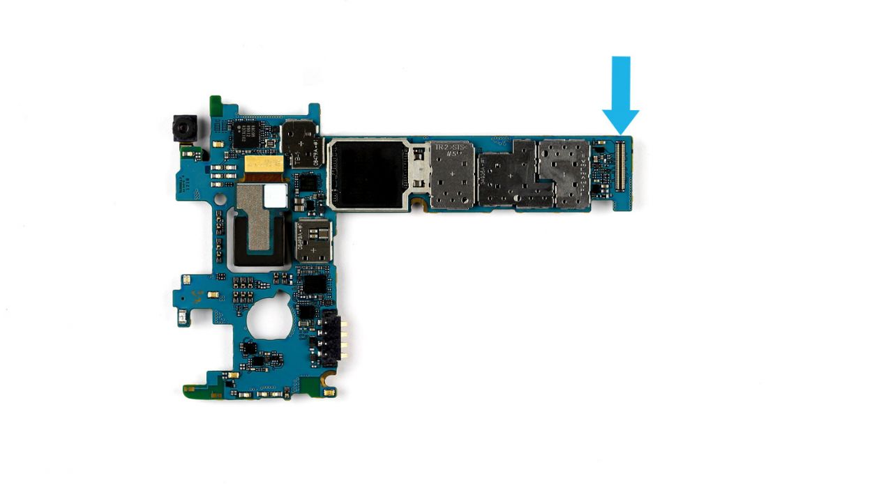

– As you get ready to install the logic board, remember to connect the sub-board to the logic board. Look for the connector (indicated by the blue arrow) located at the bottom of the logic board—it’s your buddy in this process!
– Gently tilt the logic board and position it at the top of the display frame. Then, fold it down carefully, and listen for that satisfying click as the sub-board’s connector locks into place. You’ve got this!
Step 21


– Alright, let’s get those connectors all snugly hooked up to the logic board! Follow the order below like a pro: Bluetooth antenna cable, Wi-Fi antenna cable, home button/fingerprint sensor, LCD, and touchscreen. You’ve got this!
– Now, take each connector and align it just right over its matching spot on the logic board. A gentle press on each connector will do the trick, connecting them with ease. You’re making great progress!
Step 22

– Alright, the fun part: reassembly time! Gently place the chassis back into its original spot on the display frame. Give it a little squeeze, and make sure it clicks into place on the enclosure.
– Time to secure that chassis with some screws! You’ll need 15 x 4.0 mm Phillips screws to get the job done. If you need help, you can always schedule a repair
Step 23
– Slide that microSD card into its cozy little slot, making sure it’s all lined up just right.
– With a gentle nudge from your finger, pop the SIM card into its slot, ensuring it’s perfectly aligned for a snug fit.


Step 25

– Time to pop that back cover onto your Galaxy Note Edge! Just make sure it’s lined up perfectly.
– Give the entire back cover a gentle press down onto your smartphone, ensuring that all those little clips snap into place. You’ll hear them click, and that’s your cue that it’s all set!
Step 26
– Gently slide the stylus back into your device by inserting it into the little opening at the bottom of the enclosure until you hear that satisfying click. You’re almost there!