DIY Guide to Replace USB Connector on Galaxy S5
Duration: 60 min.
Steps: 16 Steps
In this step-by-step guide, we’ll help you tackle the task of swapping out the faulty USB connector on your Samsung Galaxy S5. If your phone is refusing to charge or your computer is giving it the cold shoulder, it might be time for this repair! Just a heads-up, though: your Galaxy S5 will lose its waterproof charm after we work our magic here. If you find yourself needing a helping hand, you can always schedule a repair.
Step 1
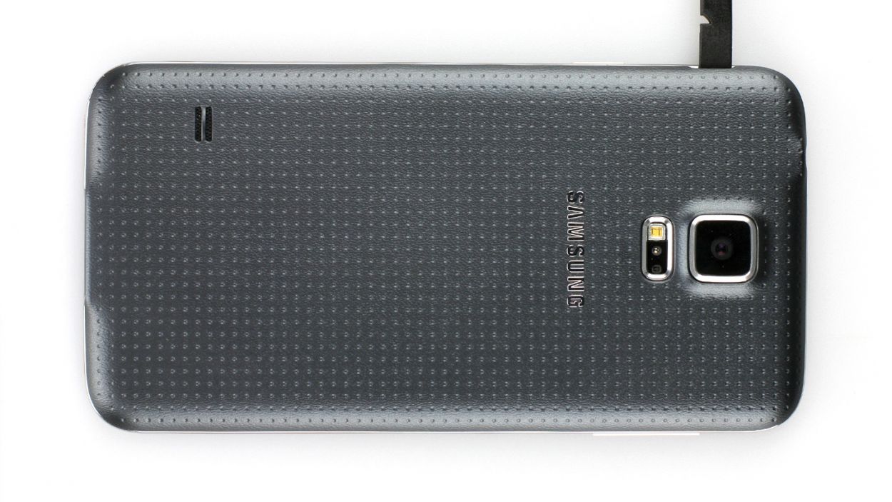
– Slide the spudger into the little gap next to the standby button. Gently lift the back cover off. There are 18 clips hanging out under there, so you’ll want to give the spudger a little dance around the smartphone to disconnect them all. If you’re feeling adventurous, you can also use your fingernails to pop off the back cover.
– Once you’ve done that, go ahead and remove the back cover!
Step 2
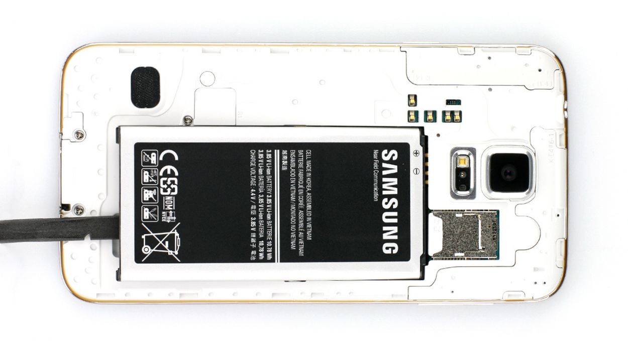

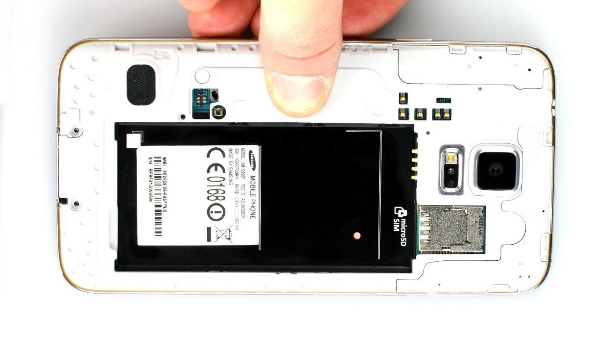
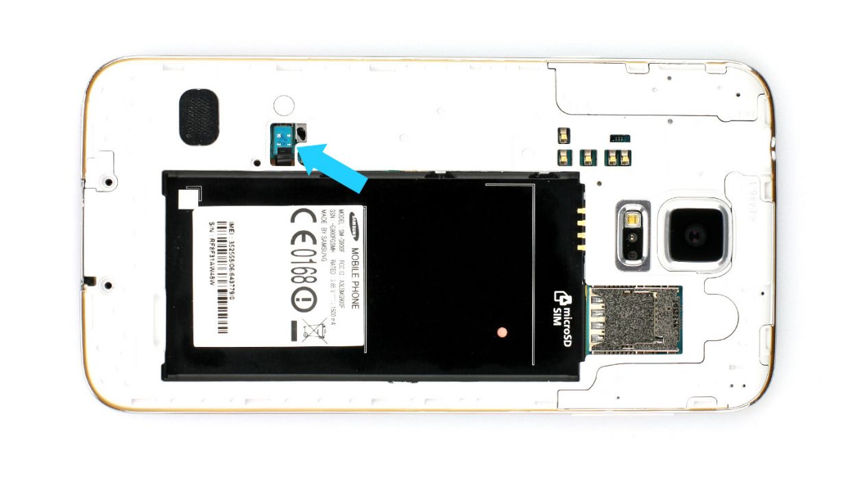
– Alright, if your Samsung Galaxy is still awake, it’s time to hit the snooze button! Press and hold the standby button for about three seconds and follow the friendly prompt on your screen.
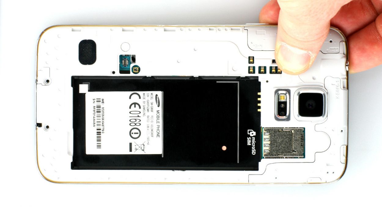
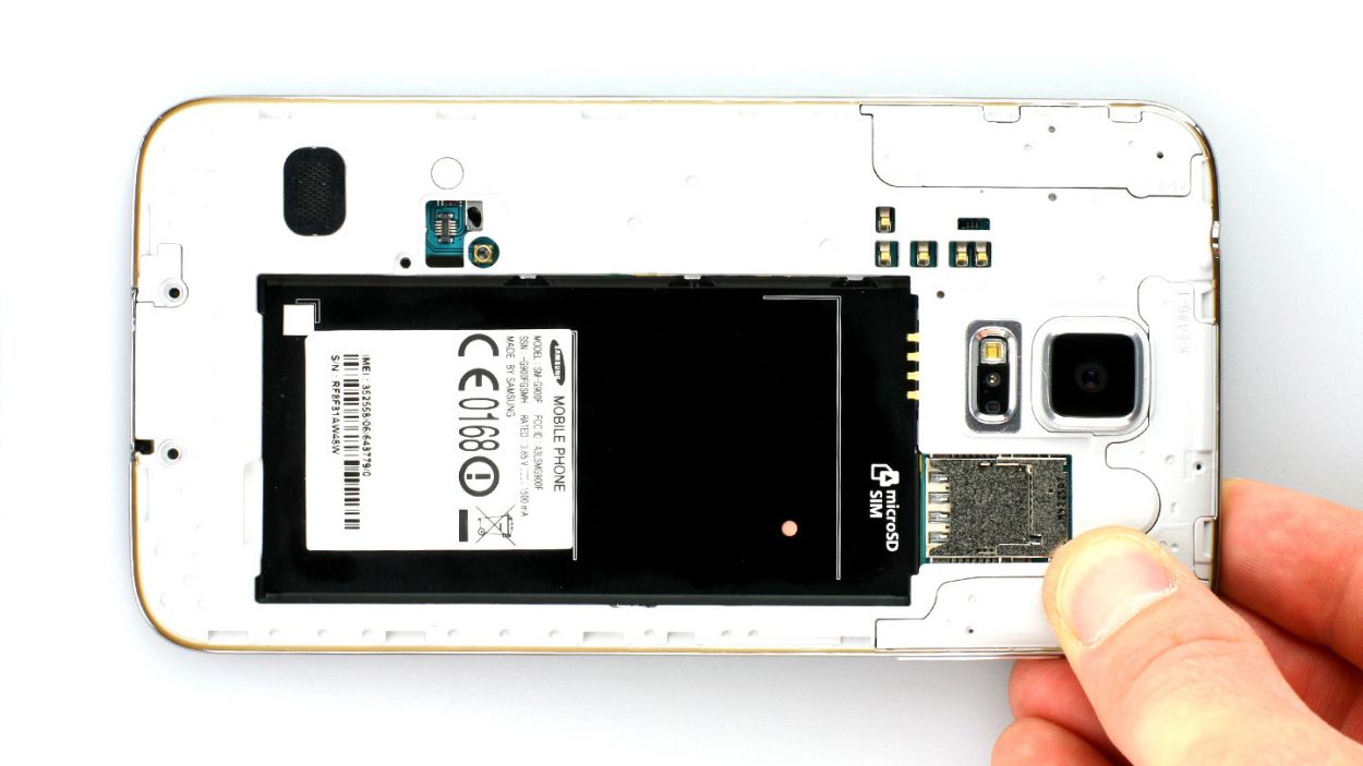
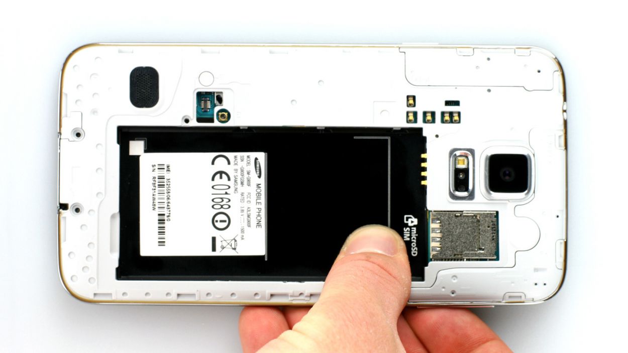
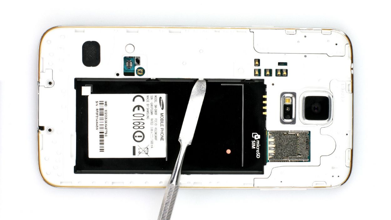
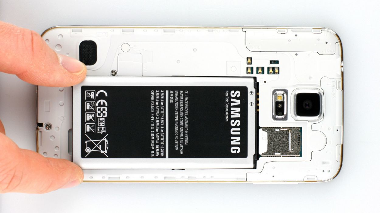
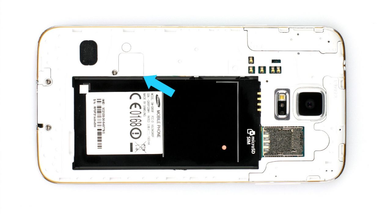
– Next up, grab your trusty spudger or just your fingertip and gently lift out the battery (check out figure 1 for some visual guidance). Once it’s up, go ahead and remove it like a pro (see figure 2 for more help).
Step 3
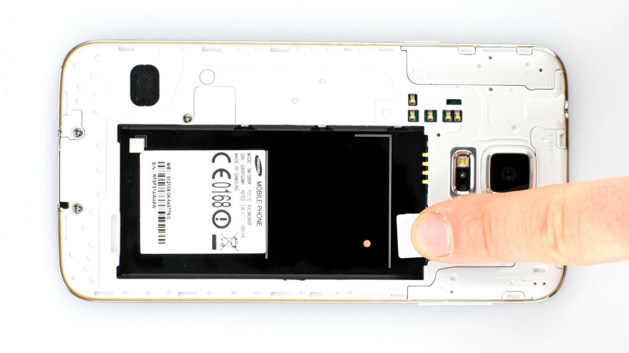
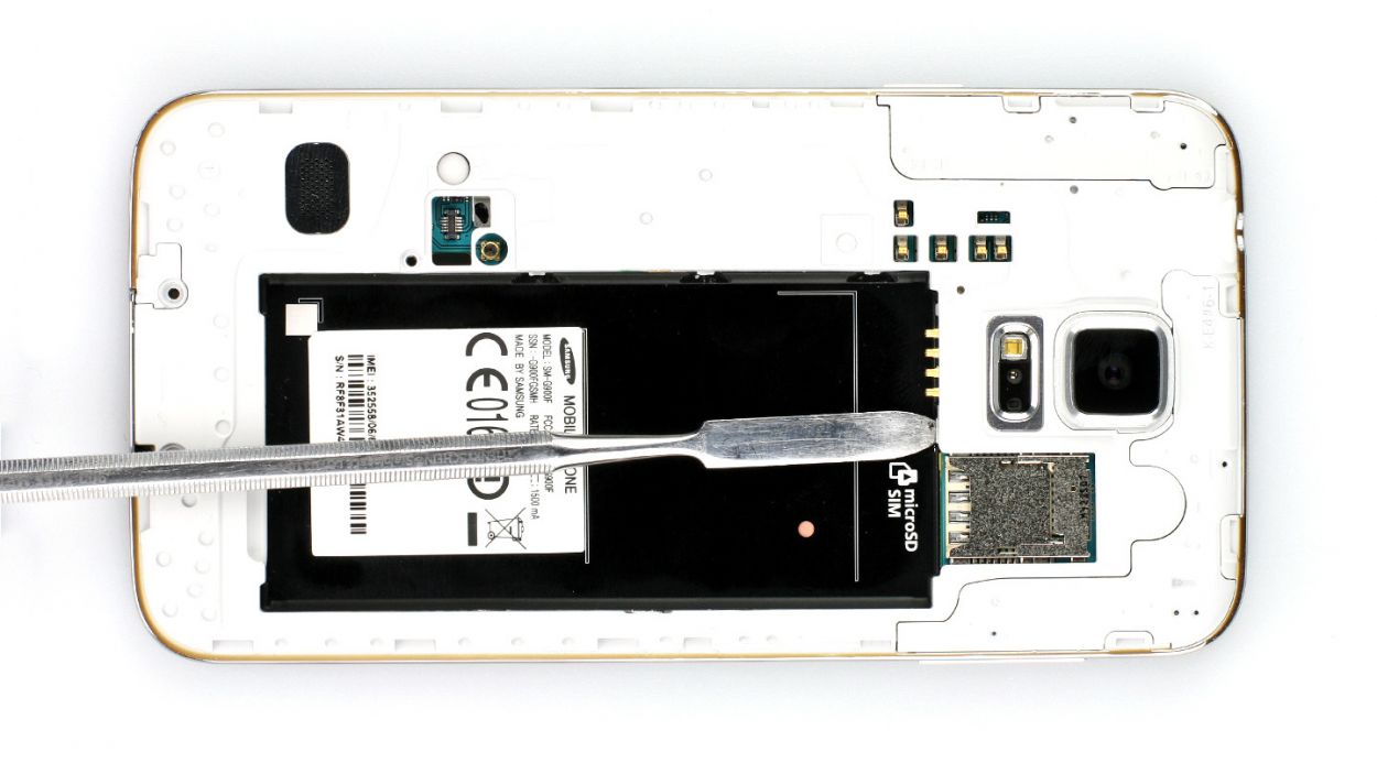
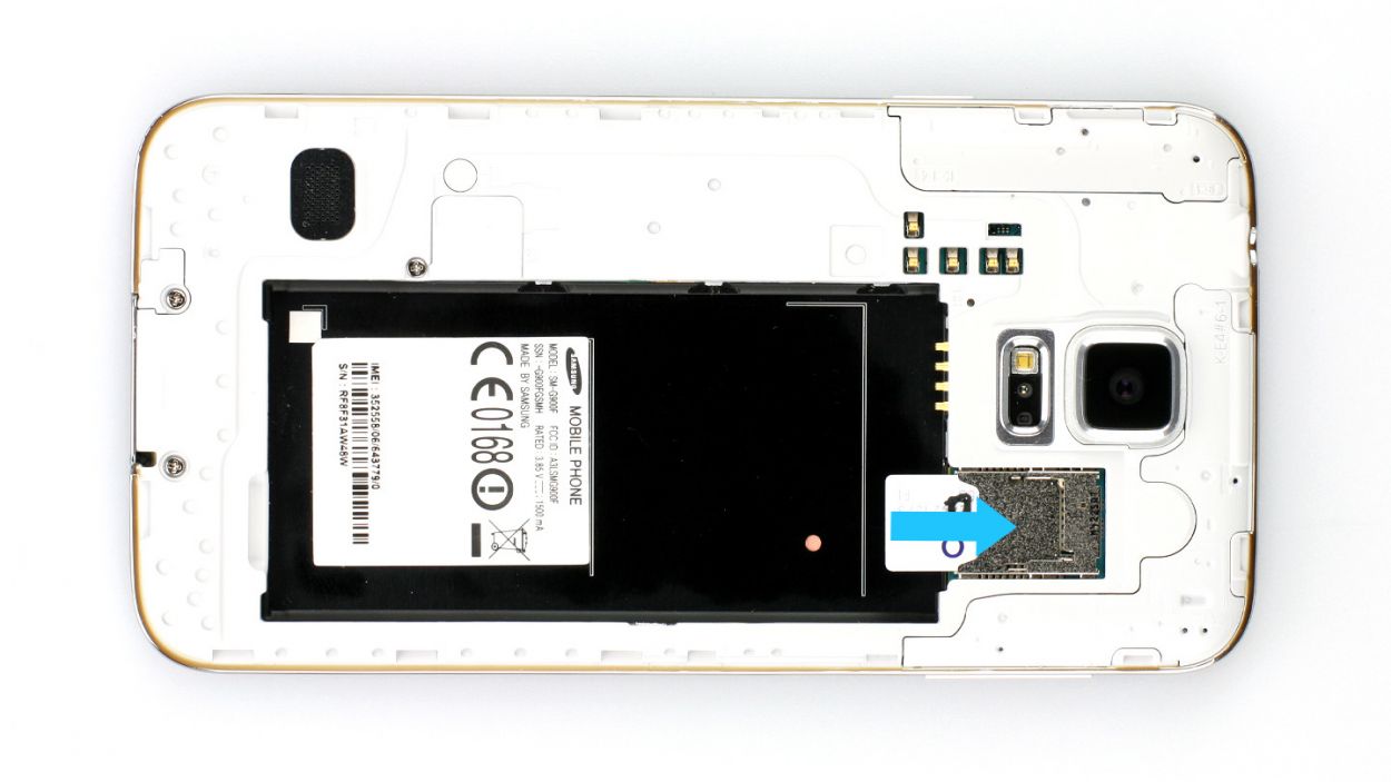
– Give that SIM card a little nudge with your finger and pop it out like a pro!
– If you’ve got a microSD card in there, just repeat the same fun process!
Step 4
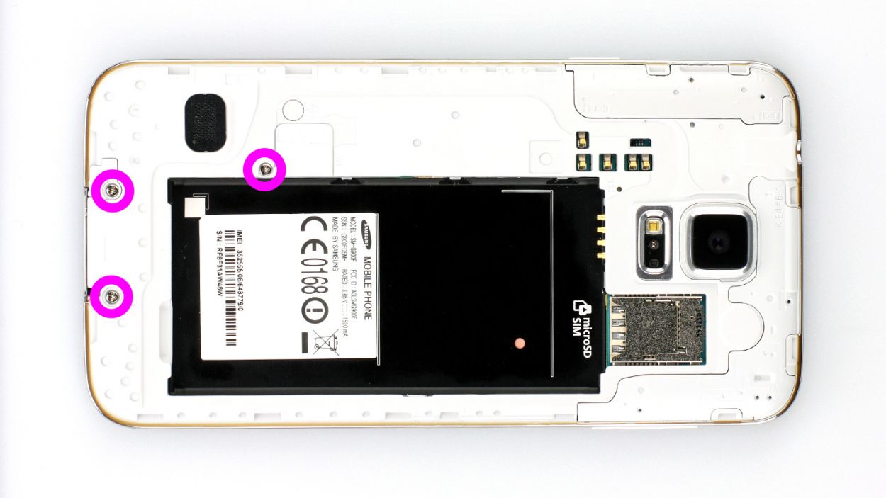
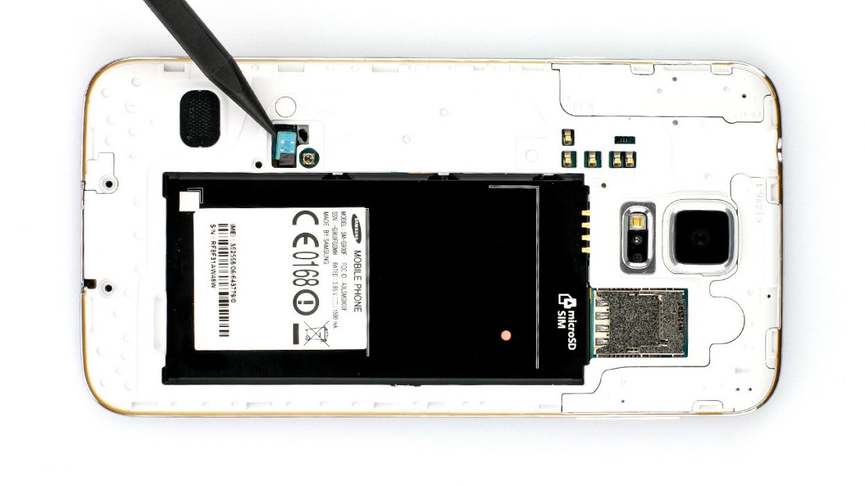
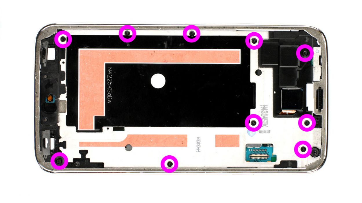
– First off, let’s get those pesky 3 Phillips screws out of the way that are keeping the upper plastic cover snug (check out figure 1)! They’re 3 x 4.4 mm Phillips screws, nothing too scary!
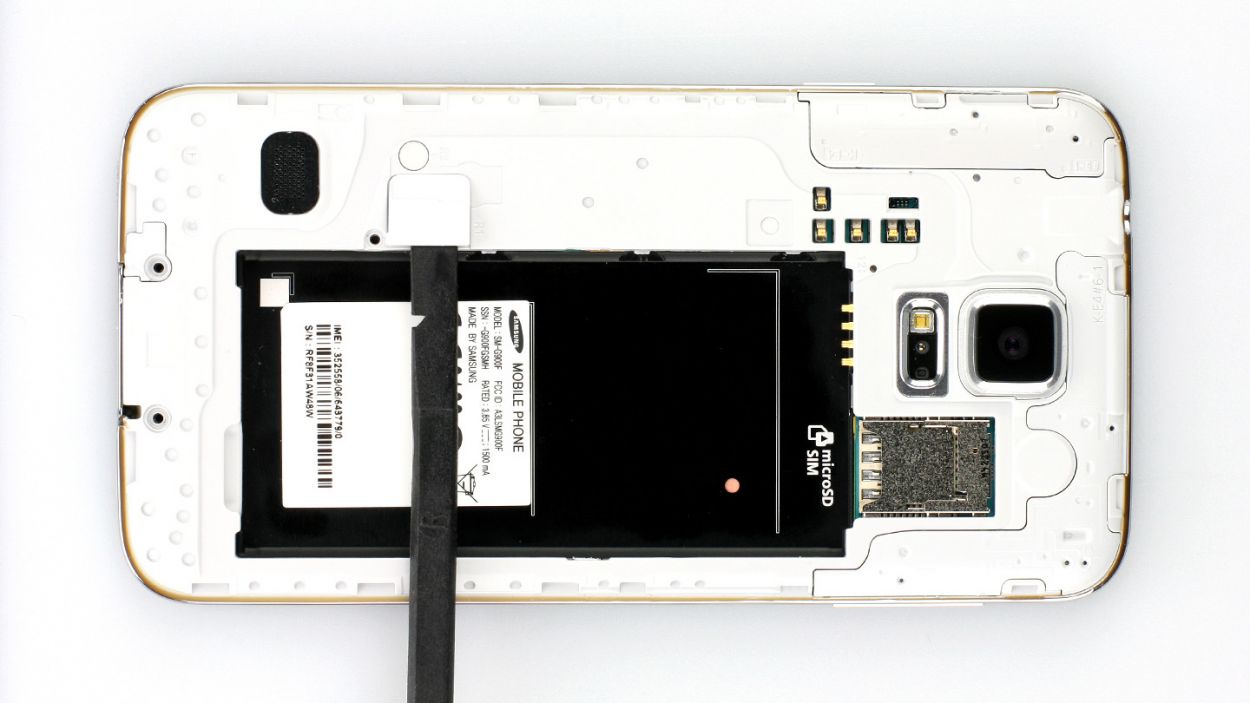
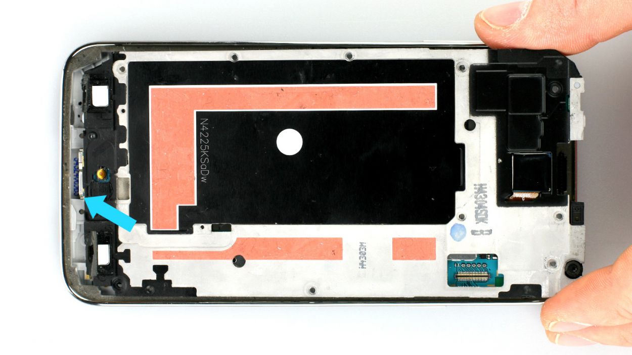
– Now, gently lift the little gray cap off (see figure 2). Surprise! The Home button connector is just hanging out right below it.
– Grab your trusty spudger with its sharp tip, and carefully disconnect that connector (see figure 3). You’re doing great!
Step 5
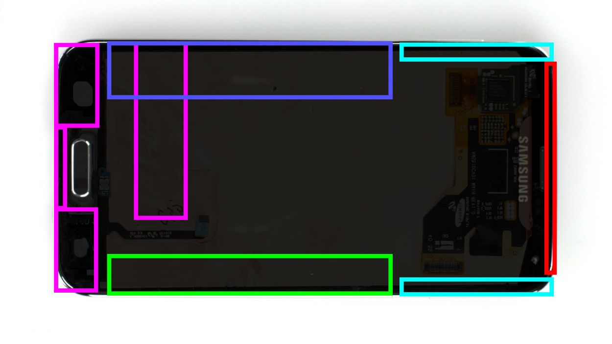
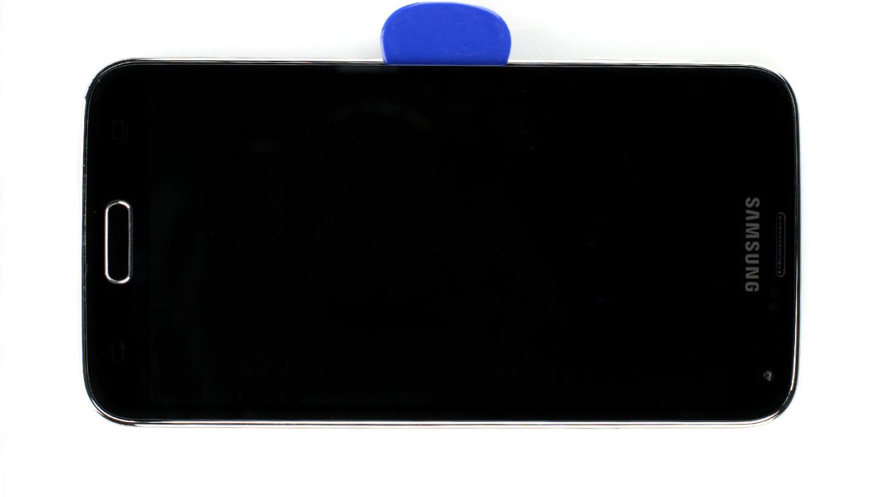
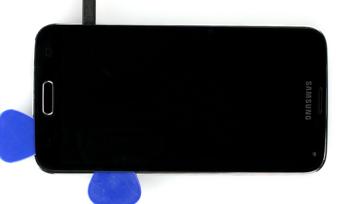

– Alright folks, let’s get started with that Samsung Galaxy S5 display! It’s stuck on there pretty well, but don’t fret. All you need is a heat gun to warm things up and soften that glue like butter. Once it’s nice and toasty, grab a plastic pick and slide it into the gap between the frame and the display to break free that adhesive. Check out Figure 1 for a little preview—it’s like a heat map for your phone’s internals, minus the weather forecast! Just make sure you heat the right section before diving into each step.
– Now, gently insert that plastic pick up to 1.7 cm (take a peek at figure 2 for guidance).
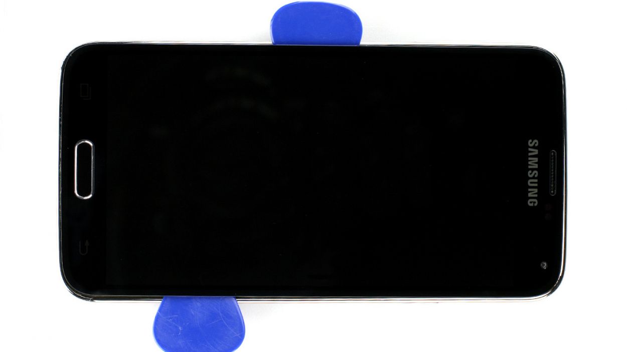
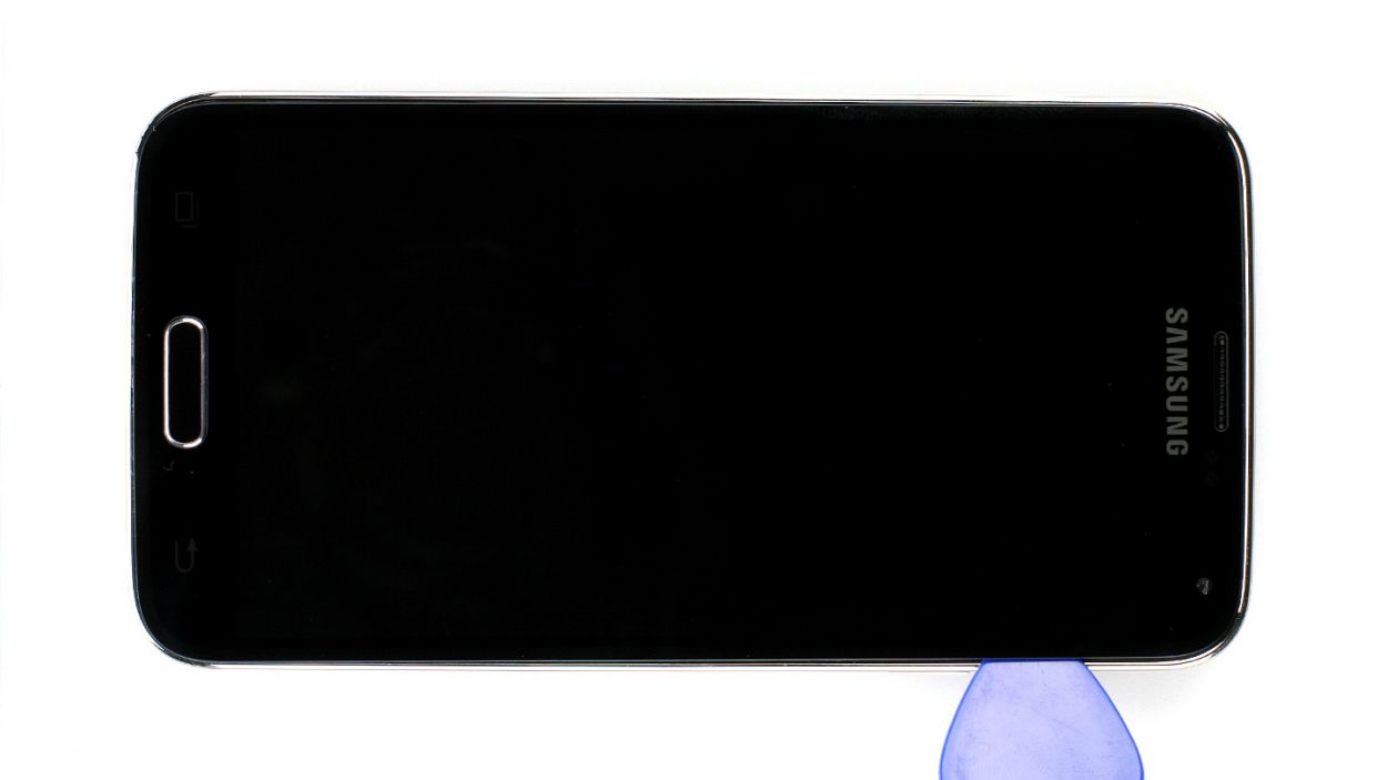
– Next up, slide the pick in deeper—go for 1.2 cm (yes, figure 3 has your back).
– Keep at it and insert the pick again to another 1.2 cm (look at figure 4 for a visual cue). Just 0.2 cm away from the Home button, and switch to that spudger for the final stretch. Don’t forget to keep heating that display and lift carefully. You’ll want to navigate that Home button cable through the midframe like a pro!
– Let’s go a little deeper—insert that plastic pick up to 0.5 cm (check out figure 5 for a reference).
– Almost there! Now, insert the pick up to 0.3 cm (figure 6 will show you where to go).
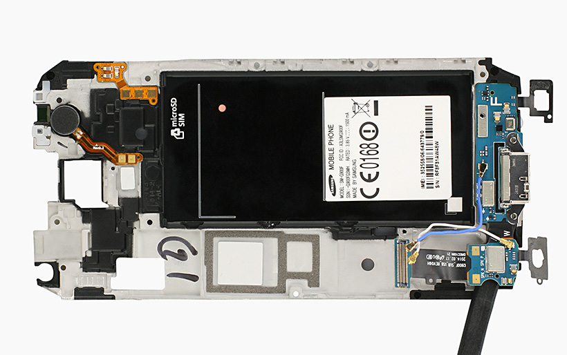
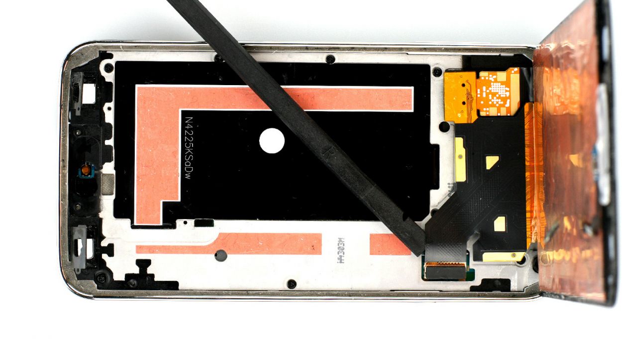
– Finally, carefully lift that display so you can disconnect the display connector from the logic board (figure 7 is your last buddy on this journey).
Step 6

– Start by taking out those 10 Phillips screws that are keeping the plastic cover in check (check out figure 1 for guidance). These are 10 x 3.3 mm Phillips screws.
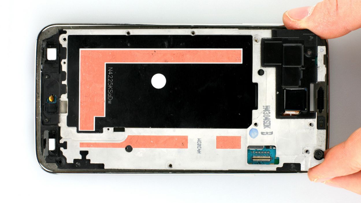
– Now, here comes the tricky bit! It requires a bit of patience. You need to separate the gray part of the frame, which has a stylish chrome-plated edge, from the rest. Gently press down on the gray frame between the headphone jack and the rear camera, while using your other fingers to nudge the outer chrome frame up (see figures 2 and 3). Then, just push out that black metal frame.
– Next up, tackle those volume buttons on the other side (see figures 4 and 5). You’re doing great!
– There are some more clips waiting for you to detach them with your trusty laboratory spatula, right where the battery used to be (see figures 6 and 7). Keep it up!
– Alright, now you can carefully lift off that gray chrome frame. Just a heads up to watch out for the dock connector (see figure 8).
– And don’t forget, there’s a little gray cover right next to the Home button that may decide to say goodbye during this process.
Step 7
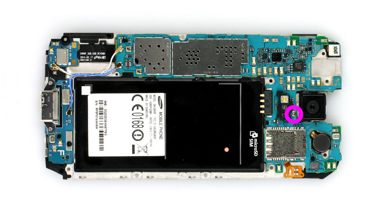
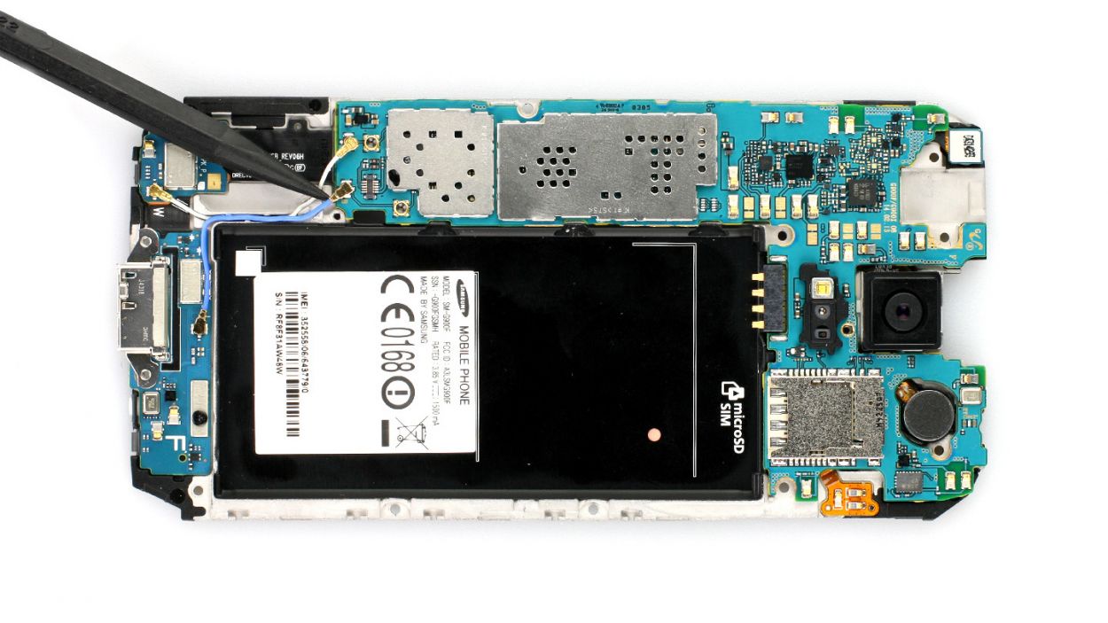
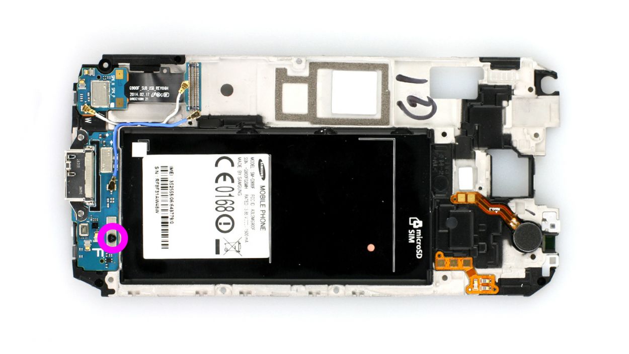
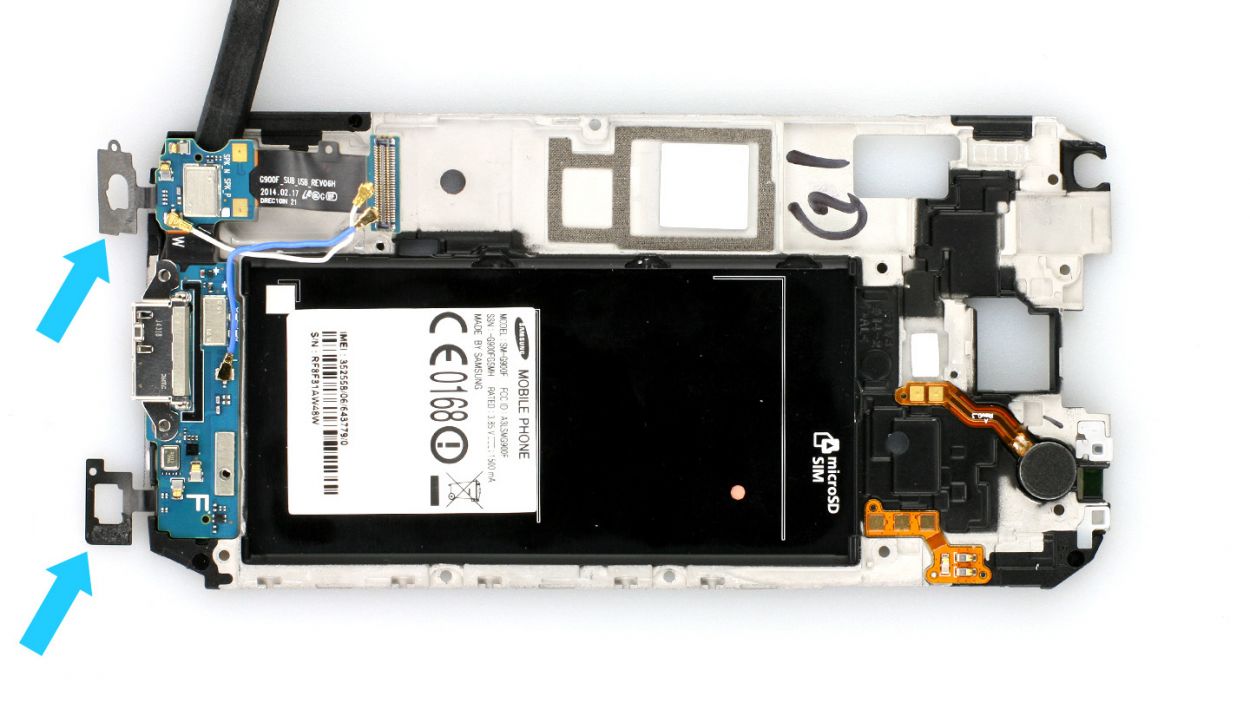
– Let’s kick things off by unscrewing the Phillips screw that’s holding the logic board snugly to the frame (check out figure 1 for a visual!). It’s just one little 3.0 mm Phillips screw, so it should be a breeze!
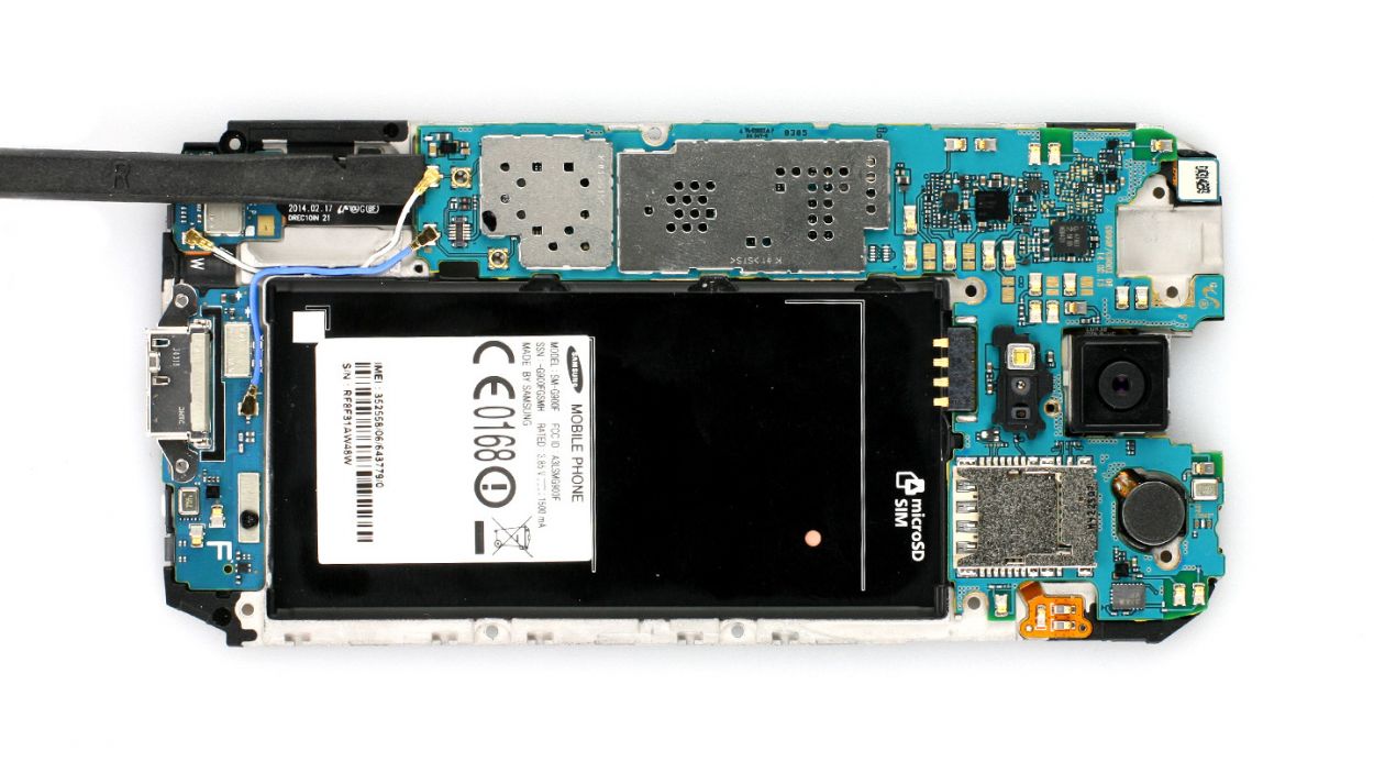
– Next up, it’s time to disconnect those white and blue antenna cables from the logic board. Grab your trusty spudger and gently lift off the cables at their heads (see figures 2 and 3 for guidance). You’ve got this!
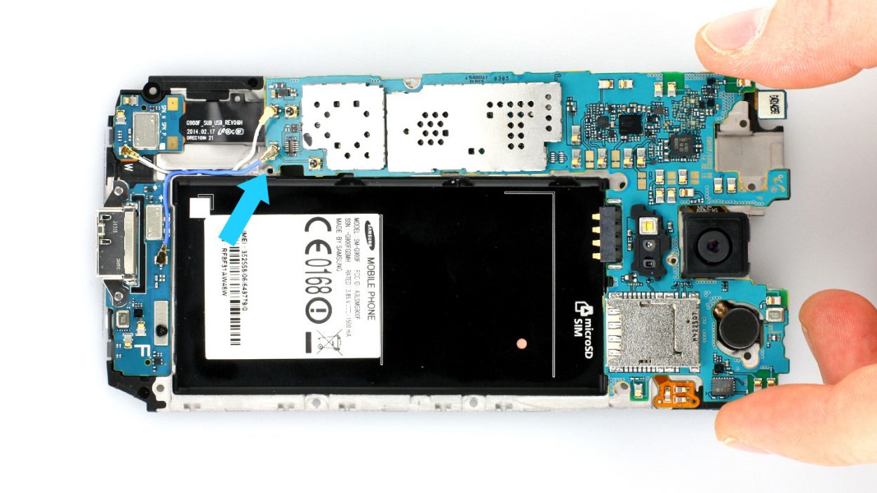
– Now, for the grand reveal! The dock connector cable is hiding just under the logic board, right where the antenna connector is. Give it a gentle disconnect (figures 4 and 5 will show you exactly where to look).
Step 8


– First things first, plug that dock connector cable into the logic board (check out figure 1) and make sure it’s snug in the frame. And hey, keep those blue and white antenna cables from getting cozy under the board (see figure 2).
– Next up, connect those blue and white antenna cables and tuck them back into the cable guide. Just a friendly reminder: be gentle, as those little contacts can get bent out of shape if not handled right.
– Now it’s time to secure the logic board with a screw (see figure 3). Grab a 3.0 mm Phillips screw and let’s get it done!
Step 9
– Alright, let’s get that interior metal frame snugly back into the gray plastic cover! Start at the dock connector (check out figure 1) and give those two frame pieces a good press together. You’ve got this!
– Once they’re cozy, it’s time to secure them with some screws. Grab those 10 x 4.0 mm Phillips screws and let’s make it all nice and tight!
Step 10

– First things first, let’s see if that old glue is still doing its job. If it’s lost its stickiness, it’s time for a replacement!
– Next up, reconnect that display cable and carefully guide the Home button cable through the metal frame (check out figure 1 for a visual!).
– Now, power on your Samsung Galaxy S5 and test out all its features. To access the test menu, just type in these magic numbers on the call app’s keypad: *#0*#.
– If everything’s working like a charm, press the display firmly onto the metal frame to secure it in place.
Step 11
– Now slide the SIM card and the microSD card, if you have one, back into the corresponding slots.
Step 12
– Pop that battery back in! Just make sure the +/- symbols are snuggling up to the contact point.
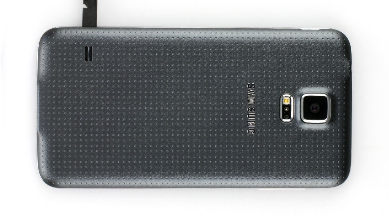
Step 13
– It’s very easy to put the back cover back on. Put it on in the correct position and press it on all the way around the phone until it’s completely clicked into place.
Step 14

– First things first, let’s get that Home button connector snugly in place again (check out figure 1 for guidance).
– Next, pop that little gray cap back on – it’ll be looking sharp in no time (refer to figure 2).
– Finally, secure the three Phillips screws that keep the upper plastic cover nice and tight (take a look at figure 3). Remember, you need 3 x 4.4 mm Phillips screws for this part!
Step 15

– First up, let’s tackle that Phillips screw keeping the USB connector snug as a bug (check out figure 1 for a little visual aid). It’s a 1 x 3.6 mm Phillips screw, so grab your trusty screwdriver!
– Next, slide that spudger beneath the USB connector cable and gently pry it away from the base (figure 2 is your friend here). It’s got a bit of glue holding it down, but don’t worry, you got this!
– Now, with a steady hand, go ahead and remove it completely. You’re doing great!
Step 16

– It’s time to gently place the USB connector cable back where it belongs. Let’s make sure it’s cozy in its spot!
– Now, fold those sensor surfaces over and secure the USB connector cable with a 3.6 mm Phillips screw. Just one will do the trick!