DIY Guide: iPhone 6s Plus Replacing Front Camera Sensor Cable
Duration: 30 min.
Steps: 12 Steps
In this guide, we’ll walk you through the process of swapping out your iPhone 6s Plus’ faulty front camera/sensor cable. If your front camera is playing hide and seek, the aperture is stuck, or your photos are coming out fuzzy, this repair is just what you need! Even if your screen isn’t dimming during calls anymore, replacing this cable will bring it back to life. And if your microphone has decided to take a break during videos or FaceTime, it’s time for a change. Let’s get started!
Step 1
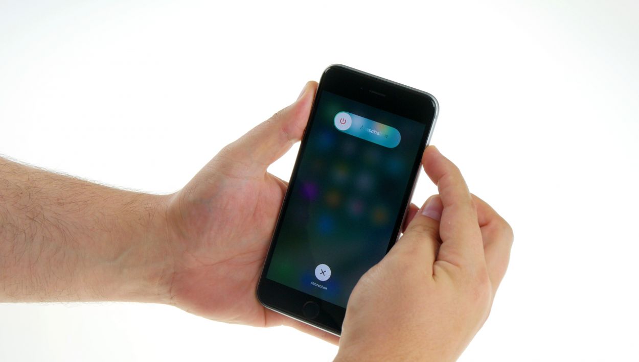

– First things first, let’s power down your iPhone to keep it safe during the fixing fun! Just press that standby button for about three seconds until you see the slider pop up.
– Now, give that slider a gentle swipe from left to right. Your iPhone will take about ten seconds to completely power down. You’re on your way to a successful repair!
Step 2

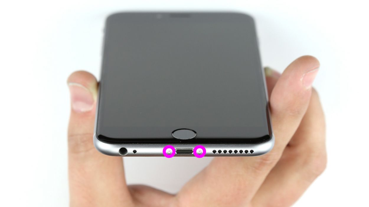
– Grab your trusty pentalobe screwdriver; it’s your key to unleashing the wonders of the iPhone 6s Plus!
– Carefully take out the two pentalobe screws hanging out at the bottom of the enclosure, just beside the Lightning connector. Remember to toss those little screws into a container to keep them safe and sound! 2 x 3.3 mm pentalobe screws are waiting to be freed!
Step 3

Risk of injury due to broken glass.
– Put your iPhone 6s Plus on a soft, clean surface to avoid scratching the back.
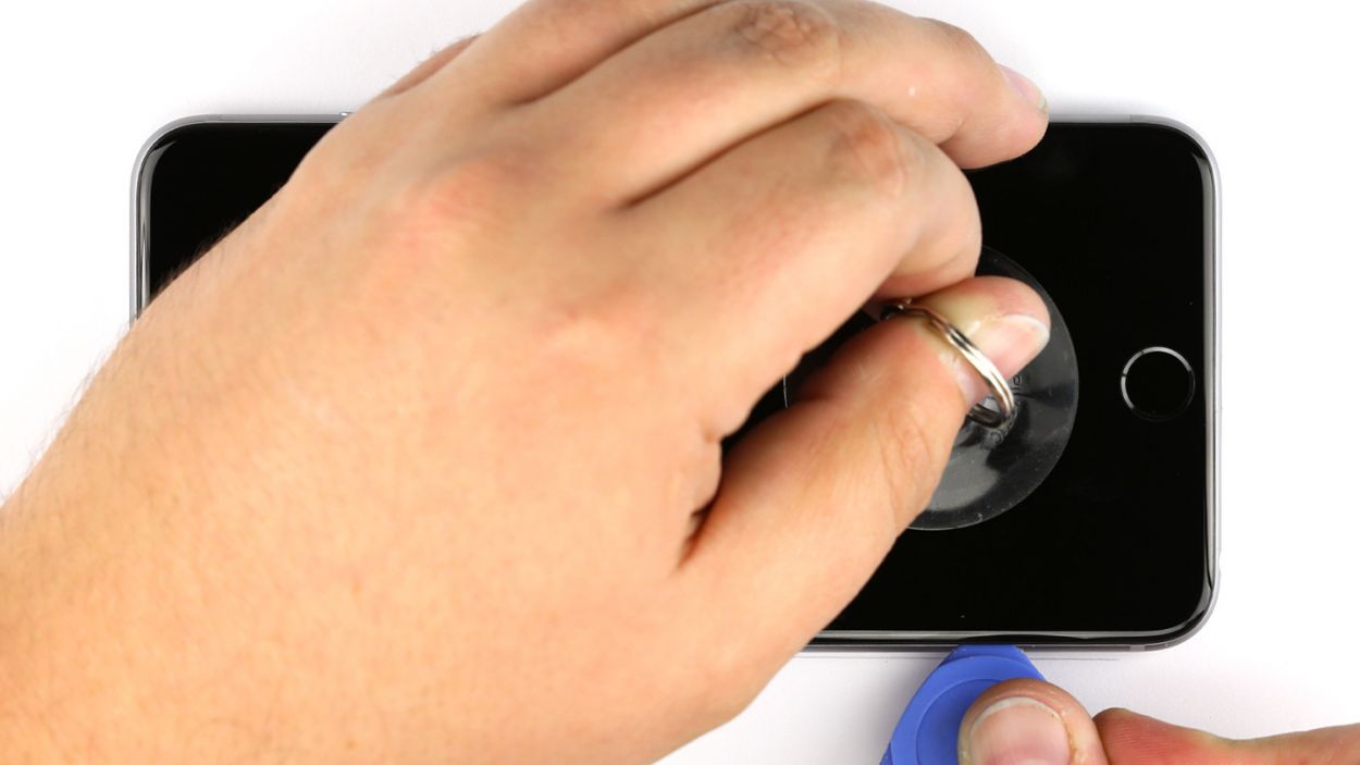
– To lift the display, you need a suction cup, a hard plastic pick and a heat gun. If the screen is severely cracked, cover all of it with packing tape before you continue.Risk of injury due to broken glass.
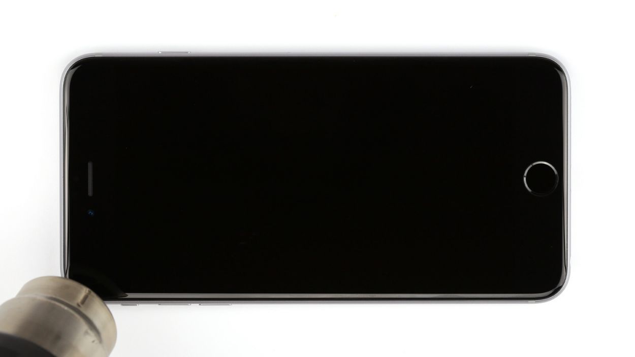
– The screen is lightly glued to the frame. Use a heat gun to heat the edges of the display to about 60°C (140°F).
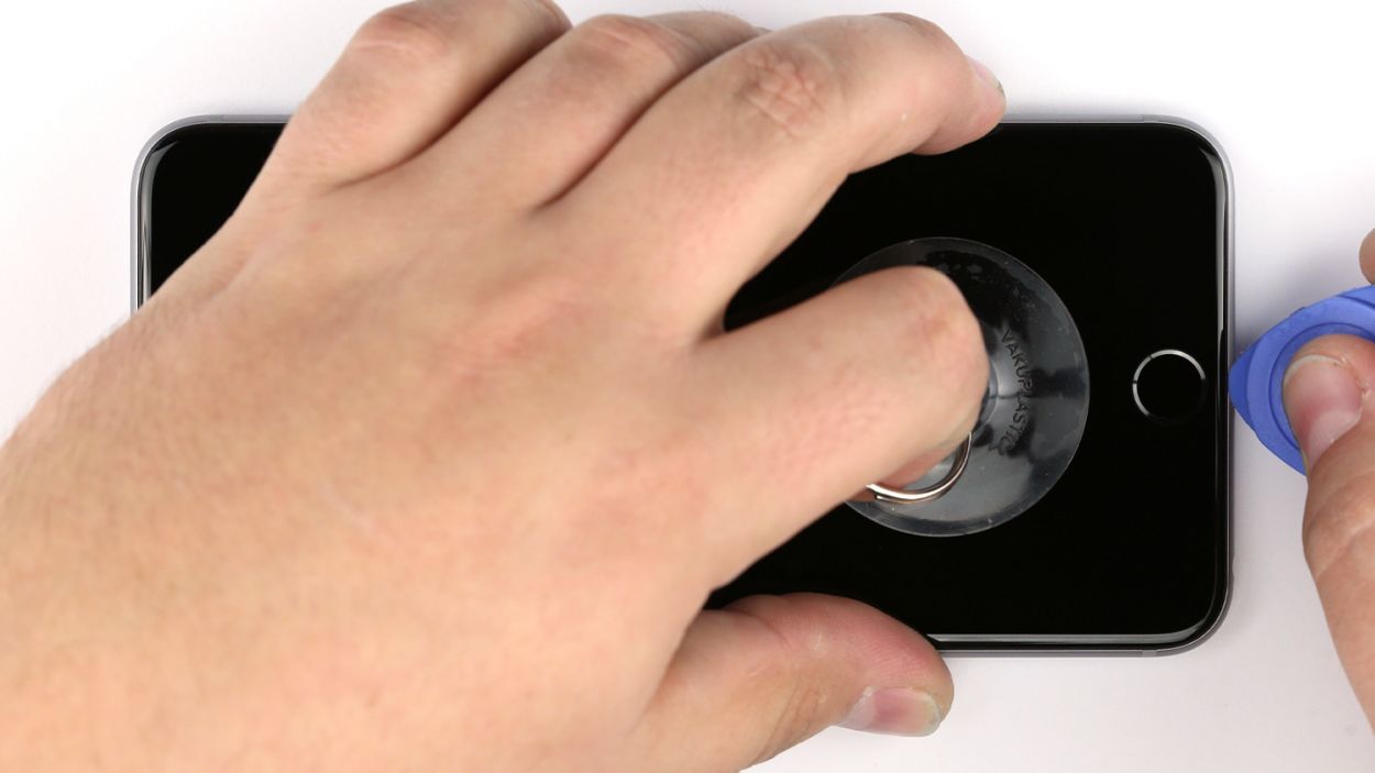
– Place the suction cup over the Home button if possible (otherwise, put it next to the button). While lifting the display with the suction cup, use the hard plastic pick to press down the aluminum frame. At the same time, insert the hard plastic pick between the aluminum frame and the display. This usually takes several attempts.
– Once a little gap has opened up between these two parts, you can open it further by slightly turning the pick.
– As soon as you can lift the display a few millimeters, you have to carefully work your way around the outside until it’s loosened on both sides.If necessary, heat the outer edges of the display a few times.
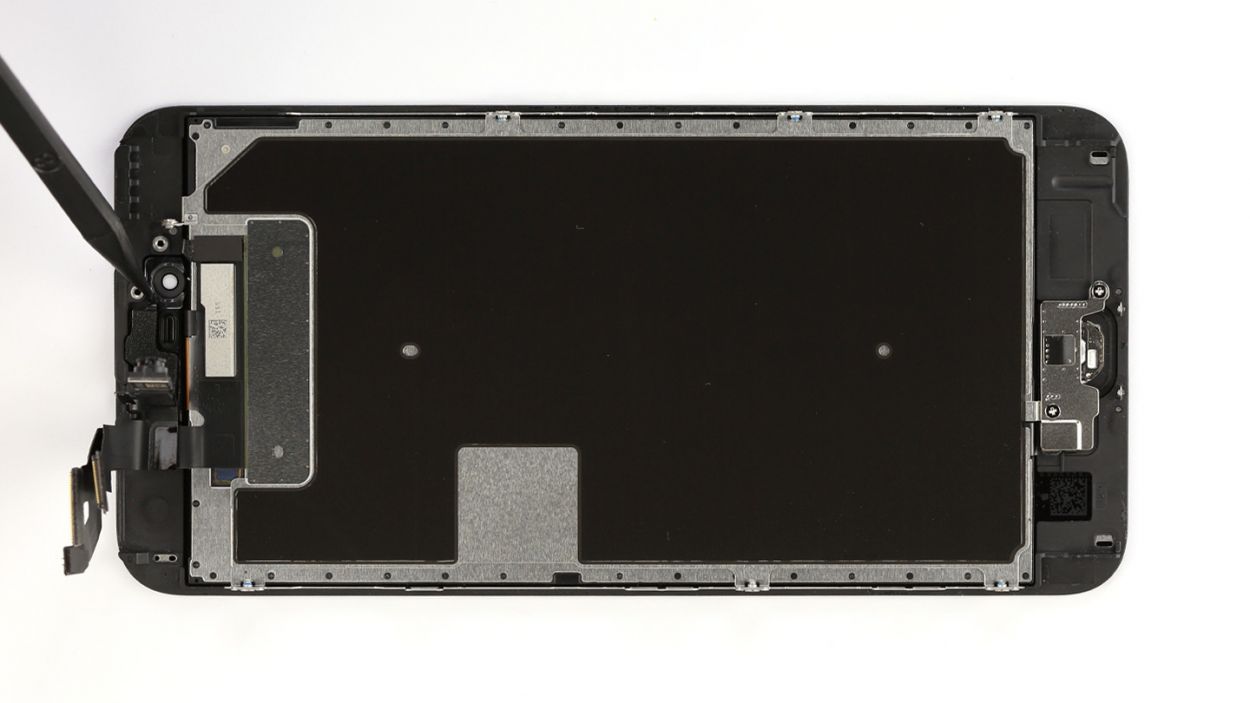
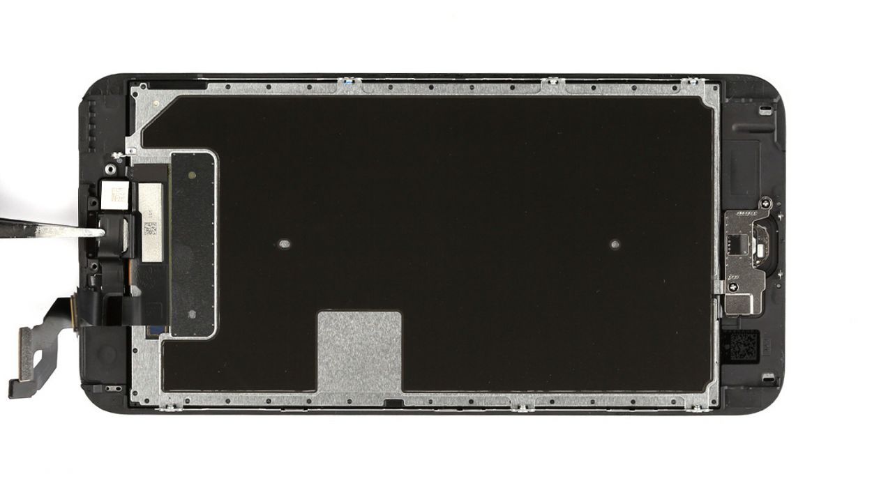
Step 4
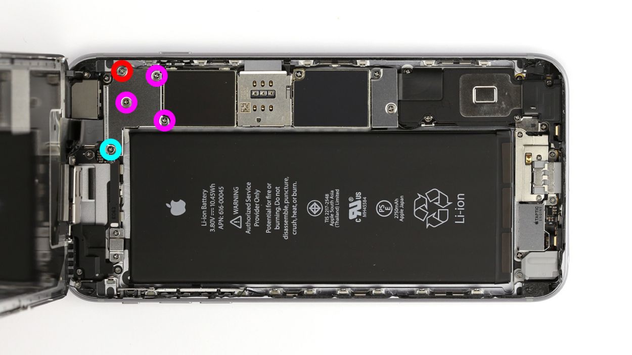

– First, let’s tackle those five Phillips screws holding down the silver cover. Make sure to keep them all together in a container so they don’t go on an adventure without you! Once they’re out, gently lift the cover off.
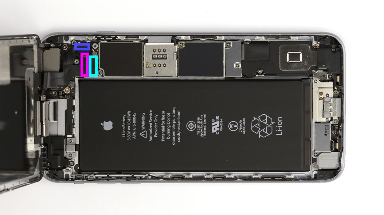
– Next up, it’s time to disconnect three overlapping connectors. Follow the order shown below and be super careful! Use the pointed tip of your spudger to gently lift each contact from just below. Here’s what you’ll be disconnecting: Touch ID cable, Front camera/sensor/earpiece/ambient microphone, and the Display.
– Now, let’s test that shiny new display! Temporarily connect the new display assembly. The LCD connector can be a bit tricky, so take your time. Power up your iPhone and check if the LCD and touchscreen are working like a charm. Ensure all connectors are snugly plugged in; otherwise, you might see a black screen or some funky stripes. If the display has a slight yellow tint, don’t forget to check the last step in this guide.
– Just a reminder, when connecting the new display assembly, take it slow with that LCD connector—it can be a bit finicky.
– Once you’ve got it connected, fire up your iPhone and see if everything is functioning properly. Double-check those connectors; if they’re not secure, you might end up with a black display or some stripes.
– And if you notice any yellowing on the display, make sure to refer to the last step in this manual for guidance.
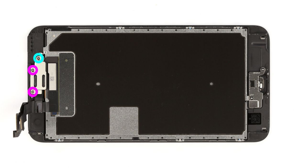
Step 5

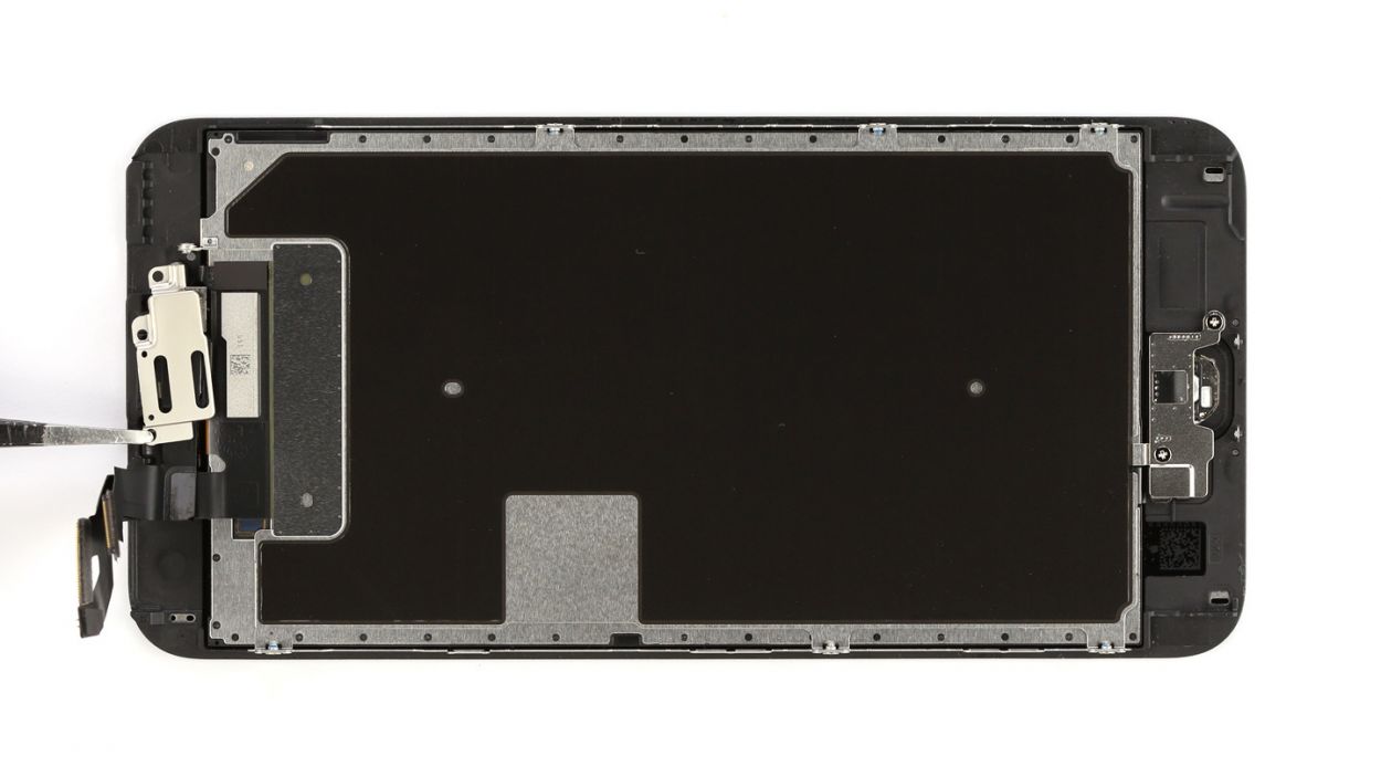
– The earpiece is hiding out on the back of the display unit. Let’s get those three Phillips screws out from the cover on the earpiece and keep them in a safe place together. You’ve got 2 x 2.7 mm Phillips screws and 1 x 1.4 mm Phillips screw waiting for you!
– Now, gently remove the cover and set it aside with the screws you just freed.
– Guess what? The earpiece is right underneath the front camera’s ribbon cable. Just fold that cable a little to the side, and you’ll be able to lift out the earpiece with ease!
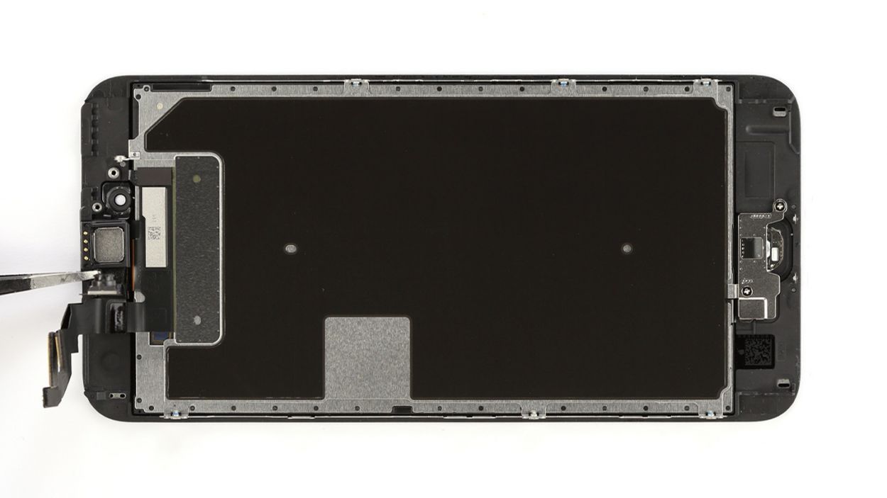
Step 6

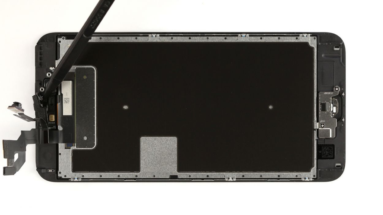
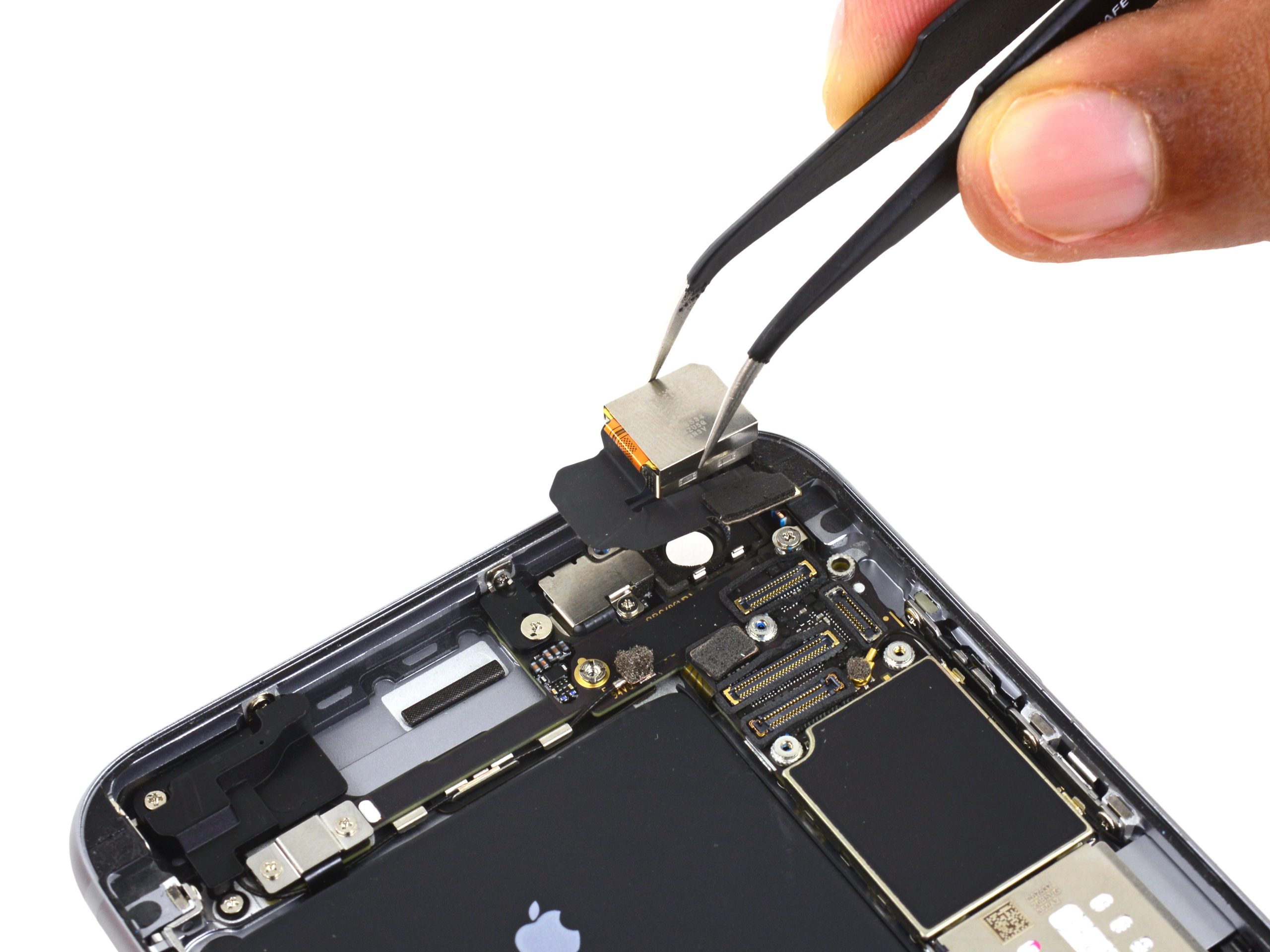
– You have to remove the cable set in two steps. First, carefully lift the sensors.
– Then insert the spudger below the ribbon cable at the point where the ambient microphone is. The ribbon cable is lightly glued in place at this point.
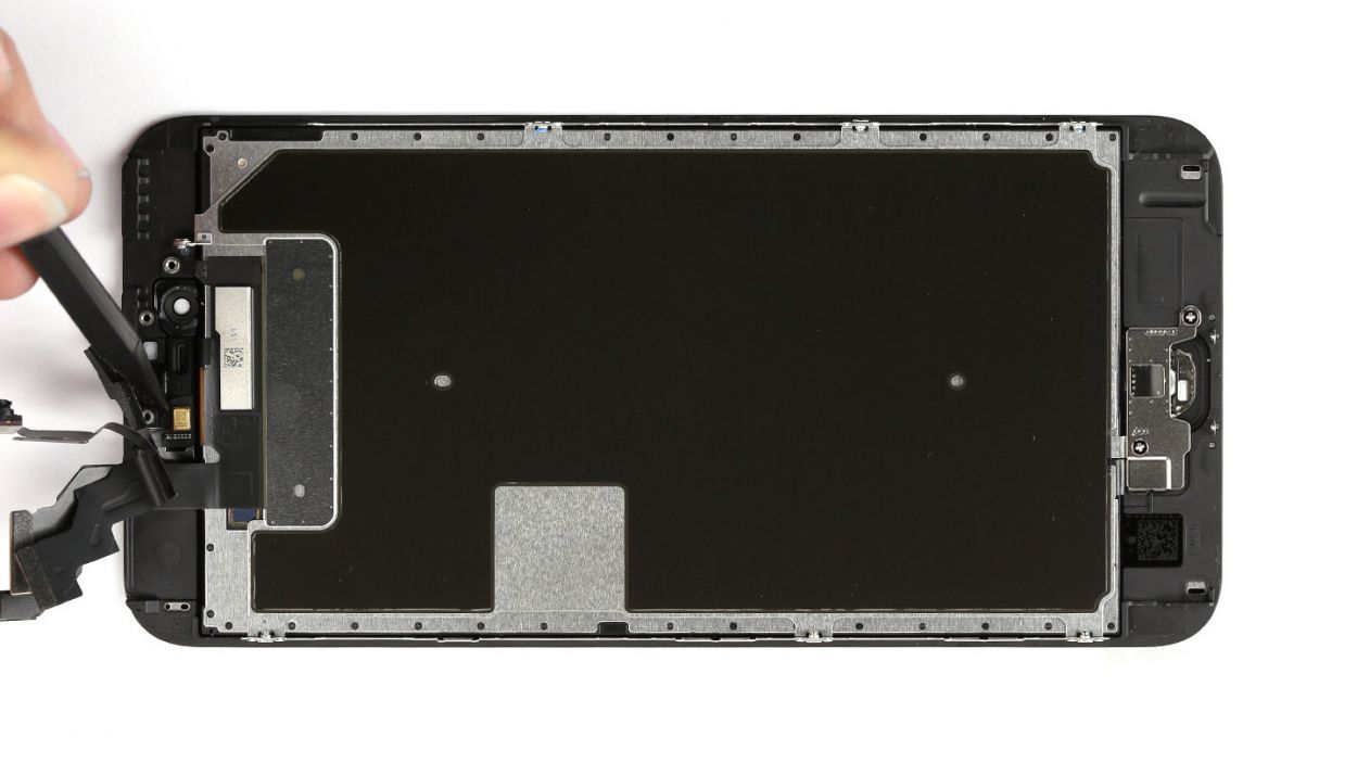
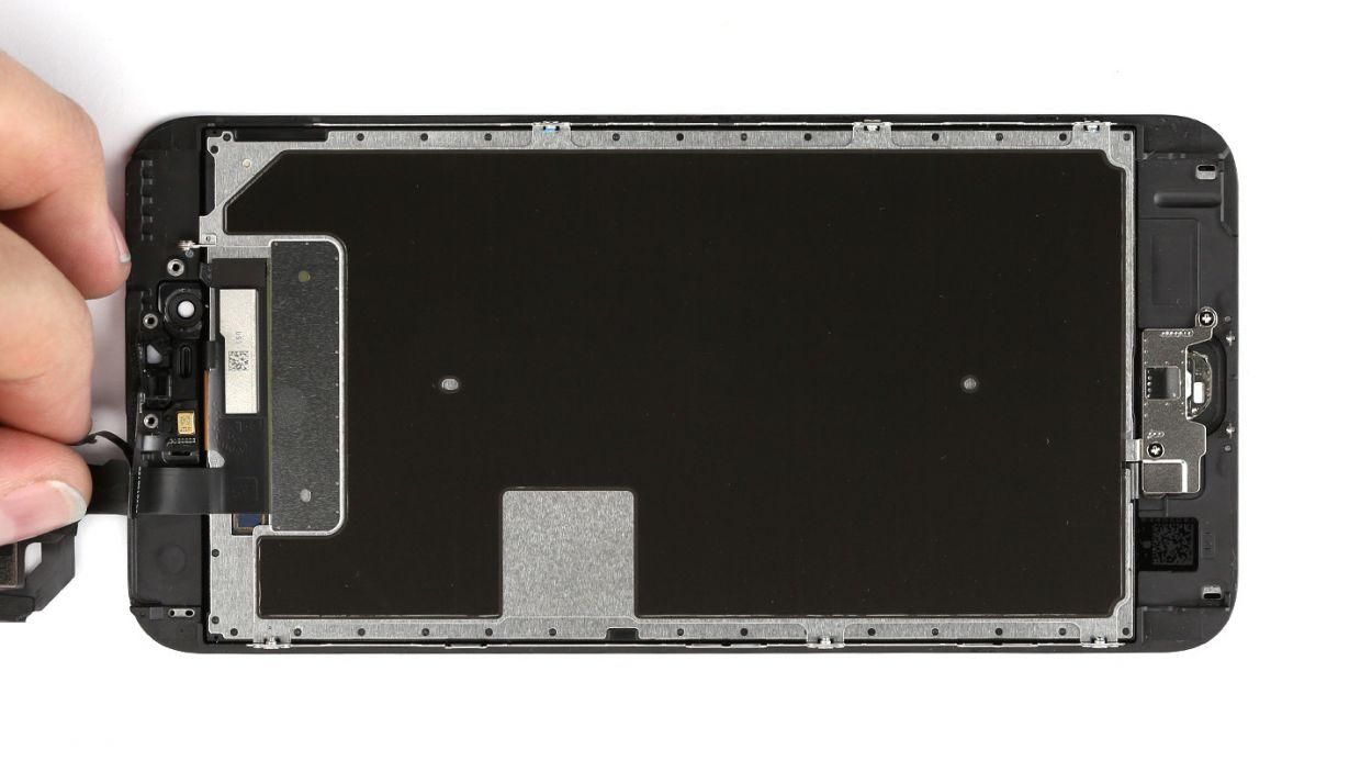
– Now you can lift out the cable set.
Step 7


It’s important to position the sensors correctly because, otherwise, the proximity sensor won’t be fully functional.
– First stick the ambient microphone to its original position.
– Then secure each of the sensors in the corresponding bracket.It’s important to position the sensors correctly because, otherwise, the proximity sensor won’t be fully functional.
Step 8


Heads up! The screws are not all the same length. If you mix them up, one might poke the display glass from the inside and cause some serious damage. So, keep them sorted and safe!
– Time to place that earpiece back where it belongs, snugly nestled between the FaceTime camera and the sensors. Once it’s in, pop the cover back on like a pro!
– Now, grab your Phillips screwdriver and tighten those screws. Just a friendly reminder: make sure the front camera is perfectly centered on the display. A little nudge here and there is totally okay if it needs adjusting. You’ve got 2 x 2.7 mm Phillips screws and 1 x 1.4 mm Phillips screw to secure everything in place!
Step 9


– Reconnect the connectors. Connecting the display connector sometimes takes a few tries. Be very careful to avoid bending the connector.Touch ID cableFront camera/sensor/earpiece/ambient microphoneDisplay
– Start your iPhone as soon as the connectors are securely attached. Check the function of the LCD, touchscreen, proximity sensor, front camera and earpiece.If the display connectors aren’t connected properly, stripes will appear on the display or parts of the touchscreen won’t work.
– Install the cover and screw it in place.1 x 2.6 mm Phillips screw3 x 1.2 mm Phillips screw1 x 1.6 mm Phillips screw
If those display connectors are feeling a bit shy and don’t connect just right, you might see some funky stripes on your screen or parts of the touchscreen might decide to take a break. Let’s make sure they’re snug and secure!
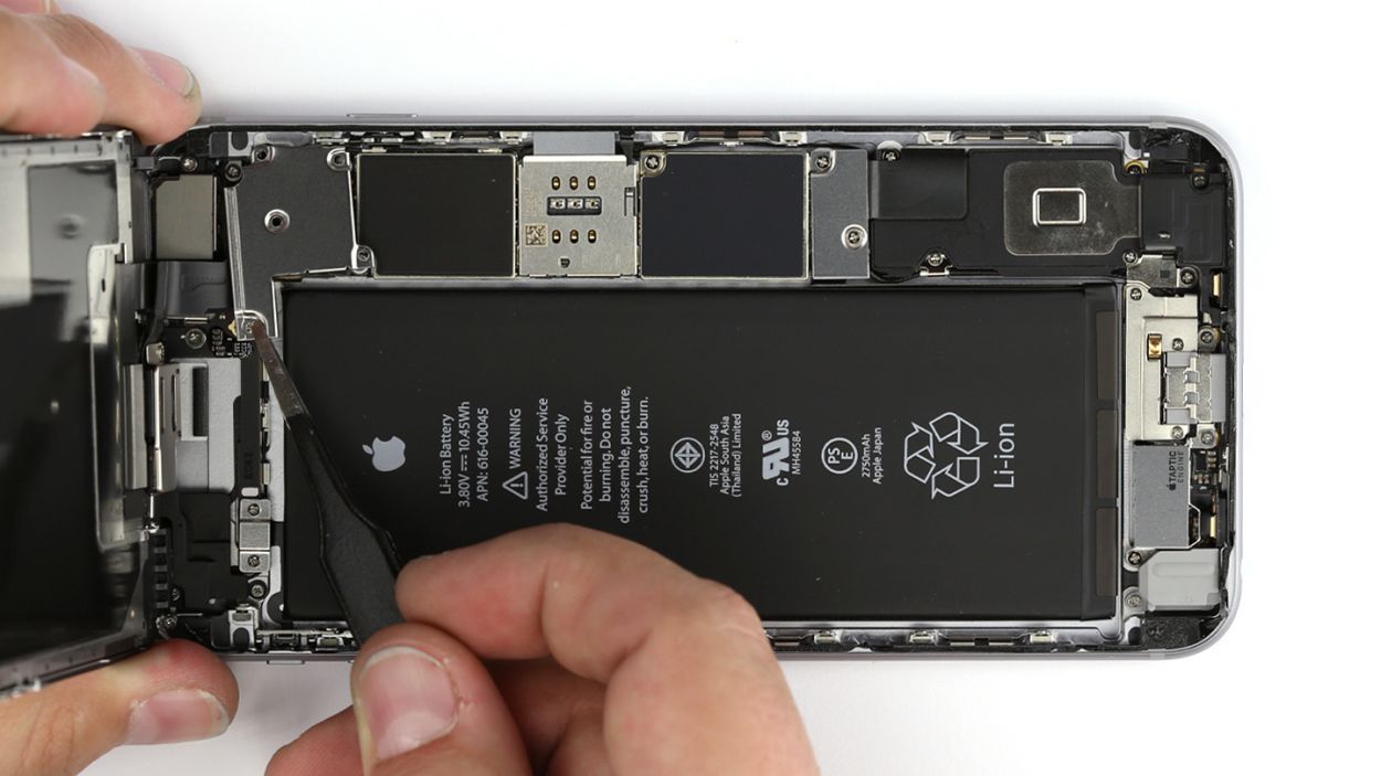
Step 10
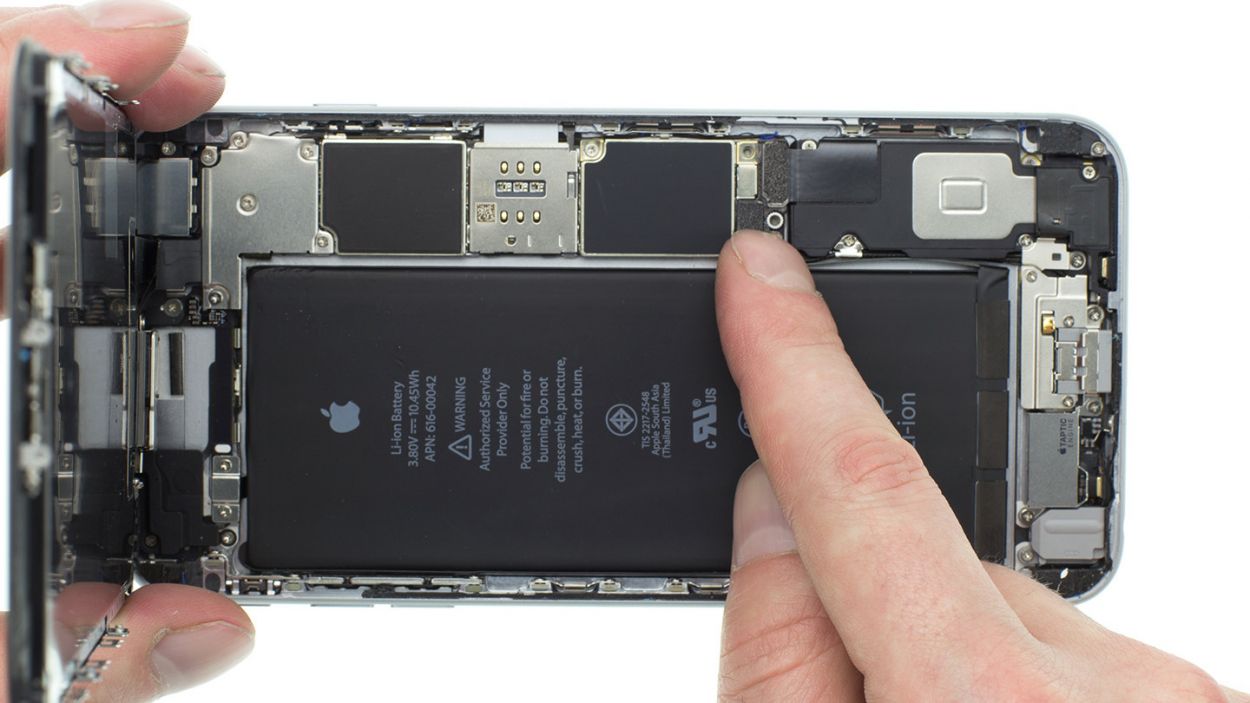

– Reconnect the antenna, Lightning connector, battery and logic board.
– Then install the silver cover again.
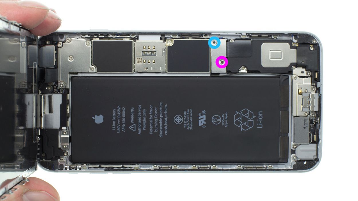
– Screw the cover onto the logic board.1 x 2.0 mm Phillips screw1 x 2.9 mm Phillips screw
Step 12
– Now screw in the two pentalobe screws at the bottom of the enclosure.2 x 3.3 mm pentalobe screw