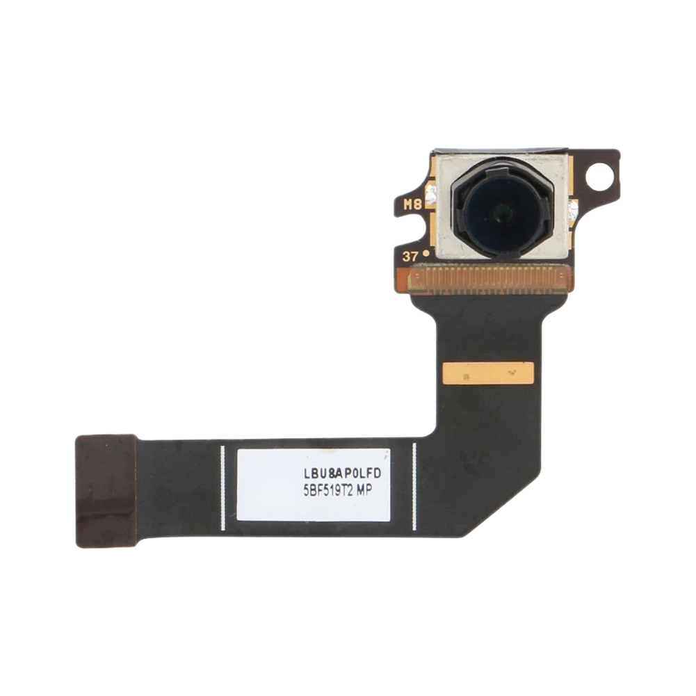
Microsoft Surface Pro 7 Rear Camera Replacement Guide
Duration: 45 minutes
Steps: 35 Steps
Be extra careful with the display panel! It’s a bit delicate and might crack if you’re not gentle. Take your time, and if things get tricky, feel free to schedule a repair.
Ready to swap out the rear camera on your Microsoft Surface Pro 7? Awesome! But a heads-up: the display panel is a bit on the delicate side, so there’s a chance it could break if you’re not careful. Make sure you apply just the right amount of heat and go easy when cutting through the adhesive. Oh, and don’t forget those safety glasses in case things go a little haywire with the glass. Take it slow and steady – you’ve got this!
Step 1


Put on your safety glasses to keep those eyes safe, and take extra care not to mess up that beautiful LCD screen. You got this!
By keeping the screen intact, you’ll prevent any glass shards from breaking apart and make it easier to pry and lift the display, making your repair much safer and more successful.
– If your display glass is cracked, let’s keep it together and avoid any cuts while you work. A quick fix is to tape it up with some packing tape.
– Start by laying down overlapping strips of clear packing tape across the Surface’s display until the whole screen is covered and secure.
– Now, take a deep breath and follow the rest of the guide. Just a heads up: Once the glass is broken, it may keep cracking as you go along. You might need to grab a metal prying tool to carefully lift out the glass pieces.
Step 2

Make sure to completely power off the Surface before you dive into the disassembly. Safety first, always!
If you’re looking for a little extra heat, a hair dryer or heat gun can do the trick. But, a friendly heads-up: be cautious not to overdo it. Both the screen and internal battery can be a bit sensitive to excessive heat. Keep it cool!
You might need to give the iOpener a few warm-up rounds to get the tablet nice and toasty. Stick with the iOpener instructions to keep things safe—no one likes an overheated tablet!
– Warm up an iOpener and gently press it against the right edge of the Surface’s screen for about two minutes to soften things up.
Tools Used

Step 3

– Take note of the screen adhesive layout before continuing:
– These areas only contain adhesive and are safe to cut.
– The display board and flex cables sit here close to the edge. Cut carefully and do not insert the pick more than 1/8 inch (3 mm).
– Fragile antenna cables lie under this part of the screen. Carefully follow the procedure in step 13 to avoid damaging them. The adhesive is also the thickest here.
Step 4


Don’t insert the opening pick any deeper than the black bezel on the edge of the screen. Inserting the pick too far may damage the LCD.
– Grab your opening pick and gently slide it into the speaker slot at the edge of the screen—wiggle it between the glass and the speaker grille to get things moving.
Step 5


– Gently rotate the pick toward the bottom of the Surface to slide it underneath the lower edge of the speaker cutout. Keep at it until you’ve got a good grip and can lift things up. If you need help, you can always schedule a repair.
Step 6


Throughout the rest of the procedure, if you encounter significant resistance while sliding the pick, stop and reheat the section you’re working on. Applying too much pressure with the pick can crack the glass.
– Gently slide the pick along the right edge of your Surface to cut through the adhesive holding the screen in place.
– Keep that pick tucked in along the right edge so the adhesive doesn’t try to seal itself back up. You’ve got this!
Step 7

– Warm up that iOpener and stick it to the bottom of your Surface’s screen. Let it sit there for about two minutes.
A hair dryer or heat gun can give you a bit more heat, but watch out—don’t overdo it. The screen and internal battery can be a bit touchy with heat, so keep it gentle and steady. If you need help, you can always schedule a repair.
You might have to give the iOpener a couple of extra heat sessions to make sure your tablet gets nice and toasty. Just remember to follow the iOpener instructions to keep things from overheating!
Tools Used
Step 8


Keep your opening pick level with the black bezel—don’t go any deeper. Pushing it in too far could mess with the LCD, and nobody wants that!
– Insert a new opening pick into the bottom right corner and slide it around the corner toward the bottom edge.
– Slide the pick along the bottom edge of the Surface to cut through the screen adhesive.
– Leave this pick in the bottom edge to prevent the adhesive from resealing.
Step 9

– Warm up your iOpener and place it along the left edge of your Surface’s screen for about two minutes.
If you’re using a hair dryer or heat gun for some extra warmth, just make sure you don’t go overboard! Too much heat can harm the Surface, especially the screen and internal battery. Keep it cool and take it easy—your device will thank you!
You might need to give the iOpener a few more rounds of reheating and reapplication to get your tablet nice and toasty. Just be sure to follow the iOpener instructions carefully to avoid going overboard with the heat.
Tools Used
Step 10


– Pop a fresh opening pick into the bottom left corner and gently glide it around the corner, moving towards the left edge.
– Work the pick along the left edge of the Surface to slice through that stubborn screen adhesive.
– Leave the pick snugly in the left edge to keep the adhesive from sealing itself back up.
Watch out when working near the bottom 2.5 inches (65 mm) of the left side. Keep the pick within 1/8 inch (3 mm) in this zone—your display cables hang close by and can be easily damaged. Once you’re past that sensitive area, avoid inserting the pick too deep past the bezel. If you need help, you can always schedule a repair.
Step 11

– Warm up your iOpener and gently press it along the left edge of the Surface’s screen for about two minutes to loosen things up.
A hair dryer or heat gun can be used to apply more heat, but be cautious—don’t let the Surface get too hot, as the screen and internal battery can be sensitive to heat damage.
The adhesive is thickest along this edge, so you might need to reheat and reapply the iOpener a few times to get the tablet nice and warm. Just make sure to follow the iOpener instructions carefully to avoid overheating and keep things safe!
Tools Used
Step 12


Heads up! The next 6 inches (15 cm) along the top edge are home to the left and right antennas, tucked right between the case and the screen bezel. Go slow and steady here to keep those antennas happy and intact.
– Grab the opening pick and gently curve the left corner, sliding it along the top edge of the Surface. Keep going until the pick is about 2.75 inches (70 mm) away from the left edge. Remember, patience and a steady hand make all the difference. If you need help, you can always schedule a repair.
Step 13


The antenna cables are tucked under the top edge of the screen, and they’re a bit delicate. Handle with care and follow the steps closely to avoid any mishaps.
– Gently slide the point of a plastic pick under the display where you’ve just made your cut. Be careful not to push it too deep past the edge of the bezel. Then, carefully tilt the pick to the right, pressing its long side into the adhesive beneath the bezel to cut through it. Keep in mind, don’t drag the pick along the edge of the Surface—just gently work it through. Repeat this process: insert the pick where you last cut, then tilt and press to the right along the top edge of the Surface. Continue this motion until the pick has traveled about 2.5 inches (64 mm) from the right edge of the Surface. If you need help, you can always schedule a repair.
Step 14


– After cutting the adhesive above the antennas (about 8.5 inches or 22 cm from the left), glide your pick along the rest of the top edge and around the top right corner to finish slicing through any leftover sticky stuff.
Step 15


Hold up! The screen is still connected to the motherboard by two cables—don’t try to pull it off just yet.
– Gently start lifting the screen assembly away from the Surface case. If it feels stuck, don’t force it – take a moment to check if all the adhesive has been fully separated.
– Grab an opening pick to slice through any stubborn bits of adhesive that are still hanging on.
– Watch out for the flash lens – it might slip out of the Surface case. Keep it safe and remember to put it back in its spot during reassembly.
Step 16


– Gently lift the top of the screen assembly away from the case, while easing the bottom of the screen towards the motherboard display connectors. Take your time with this move.
– Use one hand to keep the screen steady and in place while you make the adjustments.
Handle the display ribbon cables gently—no pulling or putting tension on them. Treat these delicate parts with care to keep everything working smoothly.
Keep your tweezers and spudger handy and within easy reach to make your repair smoother. Having these tools ready will save you time and hassle as you go along. If you need a hand, you can always schedule a repair for expert help.


Step 17


– Take the pointy end of your spudger and gently nudge each side of the battery connector—think of it as waking up a sleepy friend.
– Ease the connector out of its socket by gently rocking it from side to side, one end at a time, until it pops free.
Tools Used
Step 18


Keep that tape right where it is on the ribbon cable—no need to peel it off.
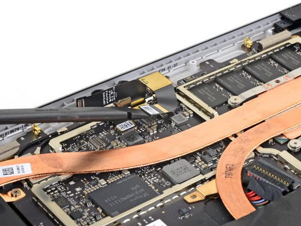
– Grab a pair of tweezers and gently lift the silver tape covering the left display cable connector. Take it slow, no need to rush.
– Next, slide the flat end of a spudger under the tape and give it a little nudge to separate the connector from the motherboard. It’ll pop right off!
Step 19


Leave the tape on the ribbon cable—no need to peel it off.
– Grab your tweezers and gently peel up that shiny silver tape holding the right display cable to the motherboard—think of it like unwrapping a tiny, high-tech present.
– Now, take the flat end of your spudger and lift the right display cable straight up to disconnect it from the motherboard. Easy does it—no wrestling required!
Step 20

– Take out the screen. When you’re back at this point in the reassembly, just follow the screen adhesive replacement guide to finish up the job. If you need help, you can always schedule a repair.
Step 21

– Grab your T3 Torx screwdriver and take out the four 2.4 mm screws holding down the EMI shield.
Tools Used

Step 22


No need to fuss over these tape pieces—they can stay put on the motherboard EMI shield. Just leave them as they are; no need for a complete removal. If you need help, you can always schedule a repair.
– Grab your tweezers and gently lift up the three strips of shiny silver tape that are holding the motherboard EMI shield to the copper heatsink. Easy does it—no need to rush!
Tools Used
Step 23

– Check out the small arrows around the edge of the motherboard’s EMI shield. They’re pointing out where the clips are that hold the shield in place.
– When you’re putting everything back together, gently press on each of these arrows to make sure the clips snap securely into place.
Step 24


Watch out for the battery! You don’t want to accidentally puncture or mess it up with your opening tool. Handle with care!
Be gentle with the EMI shield—it’s a delicate little thing, and you’ll need to reuse it. Try not to bend or warp it too much!
– Start by focusing on the clips next to the battery. Grab an opening tool and gently pry the motherboard EMI shield upwards, working your way from under each arrow to release those clips. Easy does it!
Step 25


Be gentle with that EMI shield – we want to keep it in one piece since it’ll need to go back on later!
– Keep going with your opening tool and gently work your way around the edges of the motherboard EMI shield, popping out the clips one by one. Patience is key!
Step 26

– Gently lift off the motherboard EMI shield to reveal what’s underneath. If you need help along the way, you can always schedule a repair.
Step 27

– Grab your trusty T5 Torx screwdriver and remove these four screws from the antenna bracket:
– Three 4.5mm screws
– One 6mm screw
Tools Used

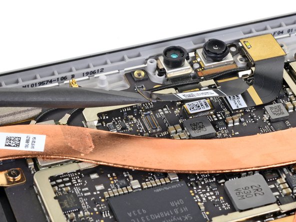
Step 28


– Grab the pointy end of your spudger and gently pop up the connector sitting next to the rear camera. Give it a little lift to disconnect it—no superhero strength required!
Tools Used
Step 29


– Grab the pointed end of your trusty spudger and gently lift the connector next to the front-facing camera to disconnect it. Take it slow, you’re doing great!
Tools Used
Step 30


– First, take off the antenna bracket. It’s just a simple pull away – no big deal!
– Next, remove the loose clear plastic light guide and set it somewhere safe for later. You’re almost there!
Step 31

– Gently pop up the Hello face camera connector using the flat end of your spudger to unplug it from the motherboard.
Tools Used
Step 32
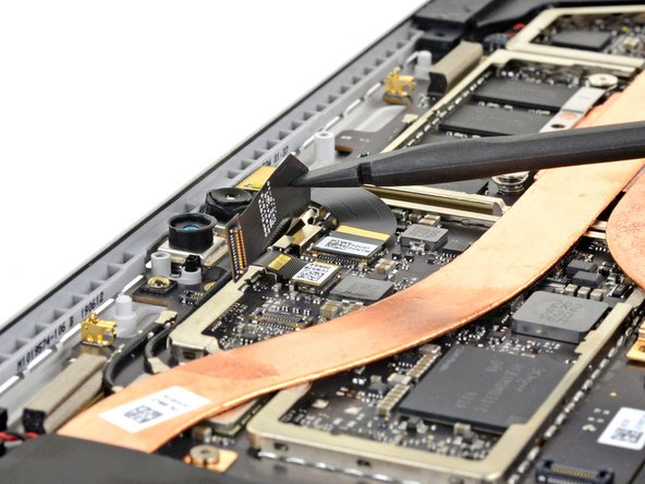

Avoid bending the cable, it’s not a yoga session. Keep it straight and steady for best results.
– Grab the flat end of a spudger and gently pry up the front camera ribbon cable from the rear camera connector. If you need help, you can always schedule a repair.
Tools Used
Step 33

– Gently pop up the rear camera connector from the motherboard using the flat end of your spudger. Easy does it!
Tools Used
Step 34

– Grab your T3 Torx screwdriver and take out the two 2.6 mm screws holding the rear camera in place.
Tools Used
Step 35

– Now that you’ve got everything back together, just retrace your steps in reverse and you’re good to go!
– Got some e-waste hanging around? Don’t just toss it—take it to an R2 or e-Stewards certified recycler to do your part for the planet!
– Something didn’t go quite right? No worries! Try some basic troubleshooting or reach out to our Answers community for a little extra guidance.
–