DIY Guide: Replace iPhone 6s Plus Standby Cable
Duration: 105 min.
Steps: 33 Steps
In this guide, we’ll walk you through the process of swapping out your iPhone 6s Plus’ faulty standby/camera flash/ambient microphone cable all by yourself! If your standby button is feeling a bit lazy or doesn’t click like it should, it’s time for a little TLC. You’ll also want to get this repair done if your camera flash or ambient microphone are throwing a tantrum. So grab your tools, roll up your sleeves, and let’s get started on making your iPhone 6s Plus happy again! If you need a hand, don’t hesitate to schedule a repair.
Step 1
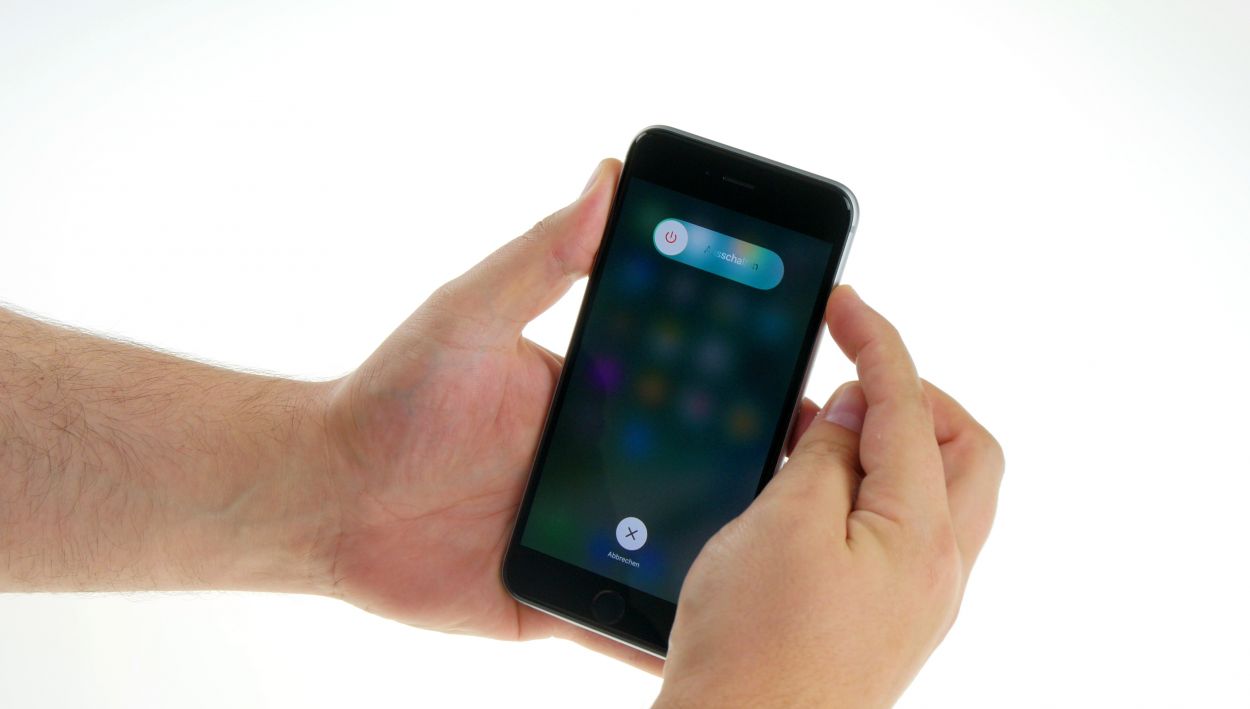

– First things first, let’s give your iPhone a little break! Power it down completely to keep it safe during the repair. Just hold down that standby button for about three seconds until the slider pops up.
– Swipe that slider from left to right and watch your iPhone gracefully shut down. This might take around ten seconds, so grab a snack while you wait!
Step 2

– Grab your trusty pentalobe screwdriver, because it’s time to pop open that iPhone 6s Plus!
– Carefully take out the two pentalobe screws at the bottom of the enclosure, right next to the Lightning connector. Remember to keep those screws safe in the same container—no one likes a lost screw! 2 x 3.3 mm pentalobe screw
Step 3
Watch out for those sneaky shards of glass! They can be a bit sharp, so handle with care while you’re working on your device.
– Place your iPhone 6s Plus on a soft, clean surface to keep that back looking fresh and scratch-free.
– To lift the display, you’ll need a suction cup, a hard plastic pick, and a heat gun. If your screen is looking a bit like a jigsaw puzzle, cover it with packing tape first to avoid any sharp surprises!
– The screen is lightly glued to the frame. Give the edges a gentle warm-up with your heat gun to about 60°C (140°F) to help loosen things up.
– If you can, position the suction cup over the Home button (if not, just beside it). While lifting the display with the suction cup, use the hard plastic pick to gently press down on the aluminum frame. Slide the pick between the aluminum frame and the display. This might take a few tries, so hang in there!
– Once you’ve created a small gap between the two parts, you can gently twist the pick to open it up a bit more.
– As soon as you can lift the display a few millimeters, take your time to work around the edges until it’s free on both sides. If needed, give those outer edges a little more heat along the way.
Step 4
– Alright, let’s kick things off! First up, grab your Phillips screwdriver and remove those two screws. Once that’s done, gently lift off the shiny silver cover. You’ve got this! 1 x 2.0 mm Phillips screw, 1 x 2.9 mm Phillips screw.
– Next, it’s time to channel your inner tech wizard! Use your trusty spudger to carefully disconnect the lower connector for the battery contact, antenna, and Lightning connector. Easy peasy!
Step 5
– To kick things off, grab your Phillips screwdriver and remove those five shiny screws from the silver cover. Remember to stash those screws in a container so they don’t go on an adventure without you! Once you’ve got those out, lift the cover off like a pro! 1 x 2.6 mm Phillips screw, 3 x 1.2 mm Phillips screw, 1 x 1.6 mm Phillips screw.
– Next up, let’s get those connectors disconnected! Follow the order shown below and take your time. Use the pointed tip of your spudger to gently lift each connector—just a little nudge below each contact will do the trick. You’ve got this! Touch ID cable, Front camera/sensor/earpiece/ambient microphone, Display.
Step 6
– The Taptic Engine is hiding under a plate, so let’s uncover it! Start by removing the three screws holding the plate in place: 1 x 2.6 mm Phillips screw and 2 x 3.3 mm Phillips screws. Easy peasy!
– Once you’ve done that, gently lift off the plate and keep it safe with the screws. You’re doing great!
Step 7
– First, let’s disconnect that contact like a pro!
– Now, grab your trusty screwdriver and unscrew the two screws holding the Taptic Engine in place. You’ve got a 1 x 2.1 mm Phillips screw and a 1 x 3.0 mm Phillips screw to tackle. No pressure, just take your time!
– Finally, gently lift out the Taptic Engine and give yourself a pat on the back for a job well done!
Step 8
– Start by unscrewing those seven Phillips screws that are keeping the speaker snug as a bug. To make your life easier later, toss those screws into different containers so they don’t get lost in the shuffle. Here’s what you’ll need: 2 x 2.2 mm Phillips screw with a large head, 2 x 2.6 mm Phillips screws, 2 x 1.5 mm Phillips screws, and 1 x 2.4 mm Phillips screw (the angled one).
– Gently pull the antenna cable to the side and place the cable guide with the 2.6 mm Phillips screws.
– Using your trusty steel spatula, carefully detach the antenna from the speaker. You’ve got this!
– With the flat end of the spudger, give a little leverage to detach the speaker from its cozy home.
– And there you have it—remove the speaker and let it take a breather!
Step 9
– First, let’s tackle those four Phillips screws! Make sure to stash them in separate containers so you can easily spot them later. You’ll need: 1 x 3.0 mm Phillips screw, 1 x 1.1 mm Phillips screw (angled), 1 x 1.8 mm Phillips screw, and 1 x 1.3 mm Phillips screw.
– Now, grab your spudger and gently use its pointed tip to detach the headphone jack along with the two shiny gold microphones. You’re doing great!
Step 10
– With your trusty steel spatula in hand, gently wiggle that Lightning connector loose. You got this!
– Slide the spatula under different sections of the flexible flat cable like a pro.
– Now, using your fingers or some tweezers, carefully coax the ribbon cable out. You’re almost there!
Step 11
– The battery is held snugly in place by three adhesive strips. Grab your tweezers and gently peel off the three black ends of those strips from the battery.
– Take your time pulling those adhesive strips off—slow and steady wins the race! If you yank them too fast, they might just tear on you.
– Now, go ahead and lift out the battery. You’re doing great!
Step 12
The silver cover has a gentle adhesive hug with the camera, so be ready to give it a little nudge to break free!
– Disconnect the camera connector by placing the spudger very slightly below the contact and lifting it up.
– Unscrew the two Phillips screws from the camera cover.1 x 2.1 mm Phillips screw1 x 1.8 mm Phillips screw
– Use the spudger to detach the camera.
– Remove the camera.The silver cover is lightly glued to the camera.
Step 13
– Time to get that SIM card tray out! Grab your trusty SIM Tool or a paperclip, and let’s make some magic happen. Just poke the SIM Tool into that tiny hole on the tray and give it a gentle press to release it. Easy peasy!
Step 14
– First up, let’s untangle those two antenna cables and disconnect the flexible flat standby cable’s connector. Easy does it!
– Next, it’s time to release the logic board! Unscrew those seven screws holding it down. You’ll need: 1 x 1.4 mm Phillips screw, 1 x 1.8 mm flathead screw, 1 x 2.0 mm Phillips screw, 1 x 2.5 mm Phillips screw, 1 x 1.1 mm Phillips screw, and 2 x 2.7 mm Phillips screws. Keep track of those screws—they can be sneaky!
– Now, gently lift off the angled plate and keep it safe with the screws.
– Remove the plate from the flexible flat volume cable’s connector and stash it with the screws.
– Finally, disconnect the flexible flat volume cable’s connector from the logic board. You’re doing great!
Step 15
– Grab that trusty spudger and gently wiggle it to disconnect the logic board from its cozy spot.
– Next up, it’s time to carefully untangle those antenna cables from the logic board. They might be clamped down at a few points, so take your time!
– Now, with a delicate touch, lift the logic board out of the back cover by angling it toward the short side. You’re almost there!
– Don’t forget, the bottom of the logic board is still connected to the Wi-Fi antenna. Give that connection a gentle disconnect and then you can fully remove the logic board. You’ve got this!
Step 16
– Unscrew those four Phillips screws like a pro! You’ll need 1 x 1.1 mm Phillips screw and 3 x 2.0 mm Phillips screws for this part.
– Gently lift out the plate that’s cradling the ambient microphone and flash. Don’t forget to keep it cozy with the screws!
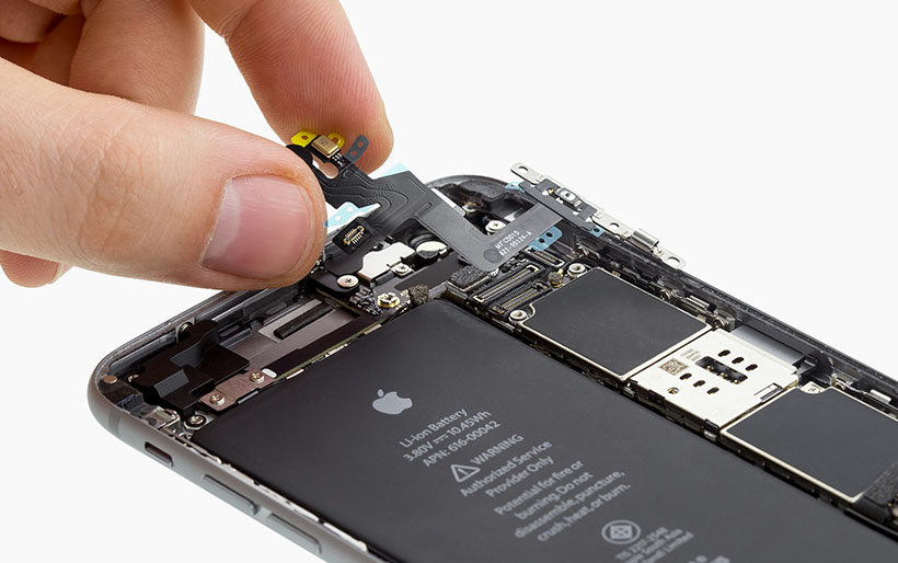
– Now, grab your trusty steel spatula and carefully detach the standby/ambient microphone/flash cable from the back cover. A little hot air can make this easier, so feel free to warm it up! Slide the spatula underneath the cable at different points until it’s fully free.
– Finally, lift that cable out of the back cover and give yourself a little high-five—you’re doing great!
Step 17
– First, let’s get that standby/ambient microphone/flash cable cozy in the back cover and stick it down nice and snug.
– Next, pop that plate back over the ambient microphone and flash like a pro.
– Finally, secure everything in place by fastening the plate with the four Phillips screws—1 x 1.1 mm Phillips screw and 3 x 2.0 mm Phillips screws. You’ve got this!
Step 18
– First, connect the bottom of the logic board to the Wi-Fi antenna. It’s like giving it a warm hug!
– Next, gently place the logic board into the back cover, but don’t squish it—leave some room for the next step!
– Finally, attach the antenna cable to the logic board. You’re almost there!
Step 19
– First, connect the logic board to the flexible flat volume cable and gently place the plate back on top.
– Next, position the angled plate back onto the logic board like a pro.
– Now, let’s secure the logic board to the back cover using the seven screws: 1 x 1.4 mm Phillips screw, 1 x 1.8 mm flathead screw, 1 x 2.0 mm Phillips screw, 1 x 2.5 mm Phillips screw, 1 x 1.1 mm Phillips screw, and 2 x 2.7 mm Phillips screws.
– Finally, connect those two antenna cables and the flexible flat standby cable’s connector to the logic board. You’re doing awesome!
Step 20
Step 21
– Place the camera back in its original spot.
– Next, secure the camera cover in place with the screws. You might find it already attached to the camera. You’ll need 1 x 2.1 mm Phillips screw and 1 x 1.8 mm Phillips screw for this.
– Finally, connect the camera’s cable. You’re doing great!
Step 22
– First, let’s peel off that big blue backing film from the adhesive strips. It’s like unwrapping a present!
– Next, stick those adhesive strips onto the back of the battery and give them a good press. Make sure they’re snug as a bug!
– Finally, gently pull away the red protective film. You’re almost there!
Step 23
– Time to give your iPhone some love! Place that battery right where it belongs, but remember, once those adhesive strips make contact with the back cover, they’re going to stick like glue!
– Peel off that blue protective film from the ends of the adhesive strips like it’s the wrapping on a surprise gift.
– Now, fold over the ends of those adhesive strips and stick them to the battery. You’re making progress!
Step 24
1 × Antenna connection
Reuse that trusty old antenna cable and connect it to the lightning connector’s flex cable (check out the image for guidance). Just snap it into place with a gentle click!
– Slide that Lightning connector back into its original spot like a champ!
– Give that flexible flat cable a good press to make sure it sticks like it should.
– Double-check that those two shiny gold microphones, the Lightning connector, and the headphone jack are all snug and fit perfectly in the frame.
Step 25
– Secure the Lightning connector using these four Phillips screws: 1 x 3.0 mm Phillips screw, 1 x 1.1 mm Phillips screw (angled), 1 x 1.8 mm Phillips screw, and 1 x 1.3 mm Phillips screw. You’re doing great—keep it up!
Step 26
– Place the speaker snugly into the back cover of your iPhone 6s Plus. Make sure those antenna cables are resting comfortably in their designated guides.
– Stick that antenna right onto the speaker; it’s like a friendship bracelet for your phone!
– Use the guide to give the antenna cable a gentle clamp against the speaker. It’s all about teamwork!
– Now, let’s secure the speaker with seven Phillips screws. Here’s the lineup: 2 x 2.2 mm Phillips screw with a large head, 2 x 2.6 mm Phillips screw, 2 x 1.5 mm Phillips screw, and 1 x 2.4 mm Phillips screw (the angled one). You’re doing great!
Step 27
– Place the Taptic Engine back in its cozy spot.
– Secure the Taptic Engine using those two trusty screws: 1 x 2.1 mm Phillips screw and 1 x 3.0 mm Phillips screw.
– Make sure to connect the contact to the flexible flat Lightning cable. You’re almost there!
Step 28
– Let’s wrap things up by placing that plate back on its rightful throne!
– Tighten it down with those three screws—1 x 2.6 mm Phillips screw and 2 x 3.3 mm Phillips screws. You’re almost at the finish line!
Step 29
– Let’s get those connectors reconnected! Sometimes, connecting the display connector can be a bit tricky, so don’t hesitate to try a couple of times. Just be super careful not to bend any connectors—nobody wants a sad connector! Here’s what to connect: Touch ID cable, Front camera/sensor/earpiece/ambient microphone, Display.
– Once everything is securely attached, fire up your iPhone! Check that the LCD, touchscreen, proximity sensor, front camera, and earpiece are all functioning like champs. If the display connectors aren’t snug, you might spot some funky stripes on your screen or find parts of the touchscreen acting a bit rebellious.
– Now, it’s time to install the cover and screw it in place. You’ll need: 1 x 2.6 mm Phillips screw, 3 x 1.2 mm Phillips screws, and 1 x 1.6 mm Phillips screw. You’ve got this!
If those display connectors are feeling a bit shy and aren’t snugly connected, you might see some funky stripes on your screen or find that parts of your touchscreen decide to take a break. Let’s make sure everything is connected just right!
Step 30
– Reconnect the antenna, Lightning connector, battery, and logic board. You’ve got this!
– Next, let’s put that shiny silver cover back on. It’s like tucking your device in for a cozy nap!
– Now, secure the cover onto the logic board using a couple of screws: 1 x 2.0 mm Phillips screw and 1 x 2.9 mm Phillips screw. You’re almost there!
Step 31
– Now, let’s gently fold down that display! Make sure it clicks into place just right at the top edge where those connection cables are hanging out.
– Next up, give the display a little nudge towards the Home button until it’s snugly fit in the frame. We want that display to be flush and looking sharp!
Step 32
– Alright, let’s get those two pentalobe screws back in place at the enclosure’s bottom, right near the Lightning connector. Remember, safety first! Keep those screws in a secure spot, you’ll need them again. 2 x 3.3 mm pentalobe screw
Step 33
When you take out the battery, your iPhone decides to throw a little time party and resets itself to 1:00 a.m. on 1/1/1970! If you don’t set the time back, you might find connecting to the cellular network a bit tricky. So, let’s get that time sorted!
– Time to sync up your iPhone! Connect it to iTunes or hop onto a WLAN network and chill until the time gets back on track.
– Carefully pop out the SIM tray along with the SIM card, then slide it back in like a pro.
– Flip on airplane mode for a quick moment, then turn it off again. It’s like giving your device a little reset dance!