Acer Iconia B1-711 V1-711 Logic Board Replacement
Duration: 45 minutes
Steps: 10 Steps
Want more awesome repair tips? Hit that subscribe button ツ
Acer Iconia B1-711 – Step-by-step guide on how to take apart the device and swap out the Logic Board. Dive in and let’s make this repair a breeze! ツ
Step 1


When lifting the cover, take care to avoid snagging the Loudspeaker cable located at the bottom right corner. It’s a little tricky, but you’ve got this!
– First, power down your tablet to avoid any accidental turns-ons.
– Next, carefully remove any SIM and/or Memory Cards to prevent damage.
– Now, let’s get started with the fun part – opening up your tablet! Begin near the Volume Up/Down buttons and use a plastic opening tool to avoid scratching the cover.
– Gently disconnect the Loudspeaker cable from the Logic board. Take your time and be patient, it’s a delicate step.
Step 2


– First things first, let’s make sure we’re safe and sound—unplug that battery before diving in!
Step 3


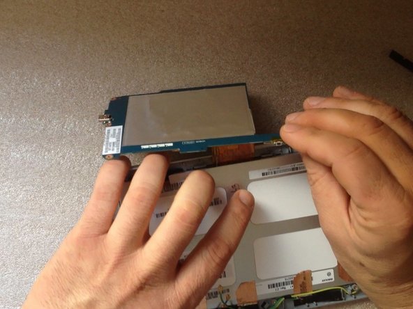
– Grab a plastic tool (a spudger works great!) and carefully work it under the battery to separate it from the metal LCD shield. Take it slow to avoid any damage.
– Lithium Ion Battery Pack – 3.8V, 2710mAh
Tools Used

Step 4
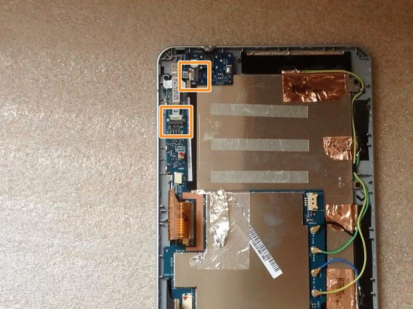

– Let’s get started! Remove the 2x Philips screws to begin the process.
– Next, carefully disconnect and remove the Audio Jack Board flex cable – it’s time to set it free!
– Now, gently remove the board with the Audio Jack Connector. You’re making great progress!
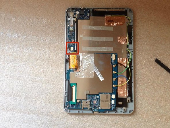
Step 5

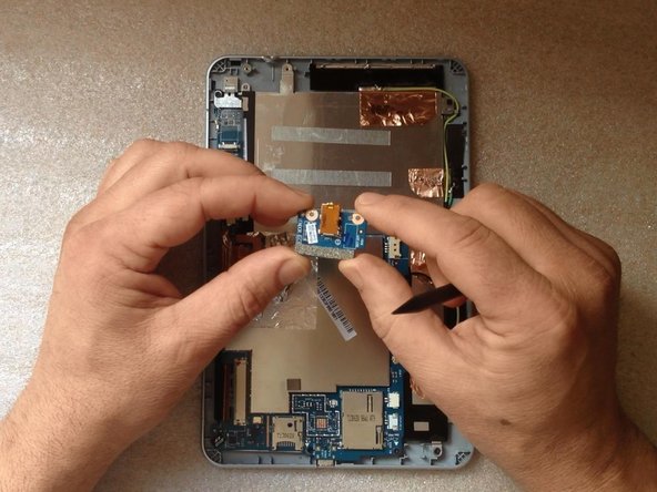
– Gently detach the audio jack flex cable—think of it like unplugging from a long call.
– Lift off the metal plate covering the camera connector—like revealing a surprise under a fancy dinner lid.
– Unhook the camera flex cable with care—it’s the key to unlocking your device’s vision.
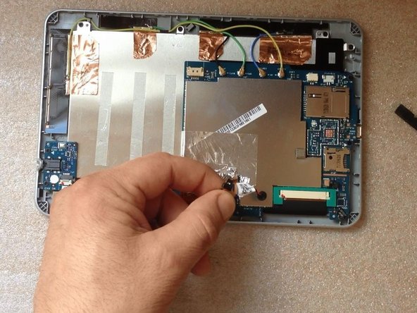
Step 6

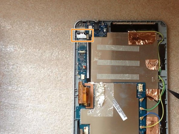
– Take out the camera.
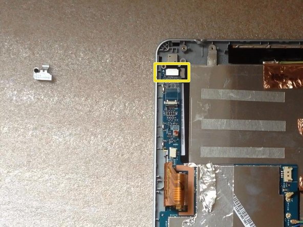
Step 7

– Time to say goodbye to that tape covering the microphone! Go ahead and peel it off with care.
– Next, let’s disconnect those microphone wires and take out the microphone itself. You’re doing great!
Step 8
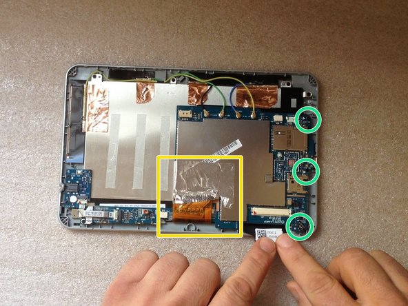


– Gently peel off the green rubber and unplug the touch screen flex cable.
– Unplug the 4 coaxial antenna cables (Wi-Fi, GPS, 3G) with care.
– Slowly lift the metal folio off the LCD display flex cable. Take your time here!
– Unscrew the 3x Phillips screws and set them aside.
Step 9


Watch out for that flex cable, we don’t want any accidents!
– Gently lift the board from the side near the battery connector, then swing it around like a pro—360 degrees around the display connector.
– Unplug that LCD display flex cable like you’re unplugging your headphones after the best jam session ever!
Step 10

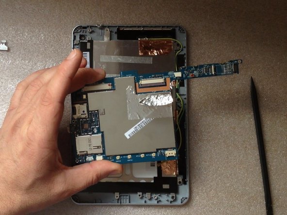
– Here we have the Logic board. Let’s dive into the details and get to know this essential component a bit better!
Success!